US2374635A - Loose-leaf binder - Google Patents
Loose-leaf binder Download PDFInfo
- Publication number
- US2374635A US2374635A US536136A US53613644A US2374635A US 2374635 A US2374635 A US 2374635A US 536136 A US536136 A US 536136A US 53613644 A US53613644 A US 53613644A US 2374635 A US2374635 A US 2374635A
- Authority
- US
- United States
- Prior art keywords
- plates
- loops
- binder
- pair
- feet
- Prior art date
- Legal status (The legal status is an assumption and is not a legal conclusion. Google has not performed a legal analysis and makes no representation as to the accuracy of the status listed.)
- Expired - Lifetime
Links
- 239000011230 binding agent Substances 0.000 title description 17
- 239000003351 stiffener Substances 0.000 description 9
- 230000037431 insertion Effects 0.000 description 3
- 238000003780 insertion Methods 0.000 description 3
- 239000000463 material Substances 0.000 description 3
- 238000010276 construction Methods 0.000 description 2
- 239000004744 fabric Substances 0.000 description 2
- 230000008275 binding mechanism Effects 0.000 description 1
- 230000000694 effects Effects 0.000 description 1
- 230000003993 interaction Effects 0.000 description 1
Images
Classifications
-
- B—PERFORMING OPERATIONS; TRANSPORTING
- B42—BOOKBINDING; ALBUMS; FILES; SPECIAL PRINTED MATTER
- B42F—SHEETS TEMPORARILY ATTACHED TOGETHER; FILING APPLIANCES; FILE CARDS; INDEXING
- B42F13/00—Filing appliances with means for engaging perforations or slots
- B42F13/16—Filing appliances with means for engaging perforations or slots with claws or rings
- B42F13/20—Filing appliances with means for engaging perforations or slots with claws or rings pivotable about an axis or axes parallel to binding edges
Definitions
- Myinvention relates to improvements in loose leaf binders imwhich the binding mechanism consists of la plurality of rings which pass throughsmall ⁇ holes arranged in a row along the binding marginof the sheets.
- the objects of my invention are to provide a loose leaf binderin ⁇ which the :rings canbe ⁇ constructed of ⁇ wire and the ring supporting structure can.l be constructed of flat material, and in which the rings of".
- the binder can be opened or closed for the purpose ⁇ of ⁇ inserting or withdrawing; sheets ⁇ withoutmanipulating the rings individually.
- a ⁇ further object of my invention is 'to provide a; binder ini which. each ring consistsof two interacting wire loops which reenforce each other and. give additional stability and rigidity to the ring binder assembly.
- H l binder ini which. each ring consistsof two interacting wire loops which reenforce each other and. give additional stability and rigidity to the ring binder assembly.
- Figure ⁇ 1 is a fragmentary top view of a book in an openedposition are 'not shown.; ⁇ 1 l Figure 2 is an elevation of the binder with the notein which the covers ⁇ covers andsheets removed; ⁇
- Figure 5 is avertical section taken ontheline 33 ⁇ of ⁇ Figure 1, ⁇ corresponding with Figure 3,
- the rings of the binder are composed of two inwardly curved wire loops 1-1 which engage each other when the loops are in a closed position by the interaction of their overlapping and underlapping end surfaces, as shown in Figure 3.
- each pair of loops describes an arc of approximately 240 degrees of a circle slightly flattened at ⁇ the top.
- loops 1-1 are each provided with short feet, 8 and 9 respectively.
- VFeet 8 and 9 are disposed in opposite directions, foot 8 being pointed inwardlylrelative to the arc genperspective of one of the points instead of one, thus dividing the strain at' the holes and counteracting the tendency of ⁇ the erally described by loop 'l and foot 9 being pointof loops 1 1 are in contact with loop supporting frame plates ID-I and back plates l2-l2.
- the effect of feet 8 and 9 being wedged in between loop supporting frame plates lll-l0 and back plates iz-lz is to support loops-J muprght and rigid positions relative to their respective back plates...4 v
- stiffener plates pin l1 and intercepted by'a stop I8 are stiffener plates pin l1 and intercepted by'a stop I8.
- stiffener ⁇ plates Iii-I6 are pulled out of engagement with loop supporting frame plates
- Figures 1, 2; and 3 show the loop supporting frame plates ⁇ lll-f-lll and back plates l2-l2 ⁇ to be of the same dimensions, this need not necessarily be so. If covers I5--l5l ⁇ are of stiff material itA may be of advantagefor them to converge as theyapproach the edges opposite thezbinding edge, as is afwell known feature innotebooks-lof: this ltype. ⁇ This can readily be accomplished by ⁇ .making back. ⁇ plates
- my invention provides a binder whose pages and covers lieflat on the supporting surface, that it lprovides a sethe pages when they are being ⁇ turned at four pages to tear loose, that it permits an indenite increase in the number of rings to be used, and that it reduces the thickness of the binder.
- each of the rings could becomposed of two overlapping prongs of hat or of arcuate cross section, each prong provided at its lower end with a pair of legs bent at their respective ends to form two feet, one foot pointed inwardly of the are generally described .by the prong, and the other pointed ⁇ outwardly thereof.
- a pair of frame plates provided with binder to be broken inwardly and longitudinally, a pair of stiffener plates one at each end of the binder pivotally mounted between one frame plate and its correspondlngback plate and in frictional contact with the other frame plate and back plate at their ends, and adapted to hold the loops in overlappingengagement when the stiffener plates are in engagement with both frame plates and with both back plates, and releasable to permit the loops to be drawn apart when the stiffener plates are taken out of such engagei inent and the back vof the binder is broken inspaced pairs of holes into which the feet are in-7 serted, a pair of back plates attached to the frame plates and retaining the feet between one back plate and its corresponding frame plate, the back plates being hingeably attached'to each other at.
- a pair of stiffener plates one at each end of the binder pivotally mounted between one back plate and rits corresponding frame plate and in frictional contact with the other frame'plate yand back plate ⁇ at their ends, and adapted to hold the prongs in overlapping engagement when the stifrener plates are in engagement with both frame plates and with both back plates and releasable to permit the prongs to be drawn apart when the stiffener plates are taken out of such engagement and the back of the binder is broken inwardly and the outer or lower surfaces of the back plates are moved into contiguity with each other on their connecting hinge.
- a plurality of pairs of wire loops curved inwardly to form rings each ring describing an are of approximately 240 degrees of a circle slightly flattened at the top, the loops overlapping at their engaging ends' to permit them to interlock detachably, each loop provided at its lower end with a pair of feet, rone Aof which is pointed inwardly of the arc generally described by the loop and the other pointed outwardly thereof, a pair of frame plates provided with pairs of spaced holes into which the feet are inserted, a pair of back plates attached to the vframe plates and retaining the feet between one back plate and its corresponding frame plate, the back plates being hingeably attached to each other at their inner edges so as to permit the back of the wardly on the hinge between the back plates to permit the insertion or withdrawal of sheets pro- 3.
- a plurality of pairs of wire loops curved inwardly to formV rings each ring describing an arc of approximately 240 degrees of a circle slightly flattened at the top, the loops overlapping at their engaging ends to permit them to interlock detachably, each loop providedat its lower end with a pair of feet, one of which isl pointed inwardly of the arc generally described by the loop, and the other pointed outwardly thereof, a pair of frame plates provided with pairs of spaced holes -into ywhich the feet are inserted, a pair of back plates attached to the frame plates and retaining the feet between one back plate and its corresponding frame plate, the back plates being hingeably 'attached to 'each other at their inner edges, a pair of covers hingeably attached to the back plates at their outer edges by a flexible covering adhesively attached tothe back plates and covers at their outer surfaces and adapted to permit movement of the back plates to a, position where they are contiguous at their outer surfaces
Landscapes
- Sheet Holders (AREA)
Description
April 24, 1945.
In ven for INI? |HIILI 2 o ,il 0 z z 5 2 71, --.-6 a z -w Mil.. u Nimh@ z z w -w mlilw Patented Apr. 24, 1945 U ,gUNlTED STATES PATENT OFFICE.
` i i l ,2,374,t35H i l l LoosE-LEAF `tirannia` e Clyde Tr Cadwallader, Kenmore, N. Y., assigner to Dorothy Cadwallader, Kenmore, N. Y. Application May 1s, 1944,` serialiNo. 536,'1315` i f 3 Claims.` (Cl. 12S- 17) Myinvention relates to improvements in loose leaf binders imwhich the binding mechanism consists of la plurality of rings which pass throughsmall` holes arranged in a row along the binding marginof the sheets.
The objects of my invention are to provide a loose leaf binderin `which the :rings canbe `constructed of `wire and the ring supporting structure can.l be constructed of flat material, and in which the rings of". the binder can be opened or closed for the purpose `of `inserting or withdrawing; sheets` withoutmanipulating the rings individually. y
1 A `further object of my invention is 'to provide a; binder ini which. each ring consistsof two interacting wire loops which reenforce each other and. give additional stability and rigidity to the ring binder assembly. H l
. 'Inthe drawing:
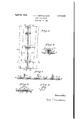
Figure `1 is a fragmentary top view of a book in an openedposition are 'not shown.;` 1 l Figure 2 is an elevation of the binder with the notein which the covers `covers andsheets removed;`
`ligureis a vertical sectionftaken onthe line 3 -1-3 of` Figure 1;
`Figure 4 is a View in wire loops; i l
Figure 5 is avertical section taken ontheline 33` of `Figure 1, `corresponding with Figure 3,
`with the rings in an opened position.
The rings of the binder are composed of two inwardly curved wire loops 1-1 which engage each other when the loops are in a closed position by the interaction of their overlapping and underlapping end surfaces, as shown in Figure 3. When in such closed position each pair of loops describes an arc of approximately 240 degrees of a circle slightly flattened at` the top.
At their other ends loops 1-1 are each provided with short feet, 8 and 9 respectively. VFeet 8 and 9 are disposed in opposite directions, foot 8 being pointed inwardlylrelative to the arc genperspective of one of the points instead of one, thus dividing the strain at' the holes and counteracting the tendency of `the erally described by loop 'l and foot 9 being pointof loops 1 1 are in contact with loop supporting frame plates ID-I and back plates l2-l2. The effect of feet 8 and 9 being wedged in between loop supporting frame plates lll-l0 and back plates iz-lz is to support loops-J muprght and rigid positions relative to their respective back plates...4 v
e `Backplates |2-I2 are hinged together .at their "inner edges by a fabric hinge Ill and are hinged at theirouter edges to `covers I5l 5 by themsame means, thel fabric hinge I 4 being adhesively attached to backplates l2-l2 andcovers l5,-l5 `Between loop supporting frame plates Ill-,l0
and back plates |2|2 at` each end, and in frictional contact therewith, are stiffener plates pin l1 and intercepted by'a stop I8. `When stiffener `plates Iii-I6 are pulled out of engagement with loop supporting frame plates |0--lll and back plates' `I2-l2 `the back of the binder can e be broken inwardly, as :isshown in Figure 5, so as to move into an openedlposition loops 1 1, permitting the insertion or Withdrawal o-fsheets i9; Sheets I9 are provided `with holes 20 into which ei-ther rowof loops l--l` are inserted. -l
Although; Figures 1, 2; and 3 show the loop supporting frame plates `lll-f-lll and back plates l2-l2 `to be of the same dimensions, this need not necessarily be so. If covers I5--l5l` are of stiff material itA may be of advantagefor them to converge as theyapproach the edges opposite thezbinding edge, as is afwell known feature innotebooks-lof: this ltype. `This can readily be accomplished by `.making back.` plates |2--I2 slightly wider than loop supporting frame plates lll-IIJ, thus causing them to project slightly beyond the lines of the loop supporting frame plates at their outer edges. `Such an arrangement is shown in Figure 5. `l l The advantages of my invention are that it provides a binder whose pages and covers lieflat on the supporting surface, that it lprovides a sethe pages when they are being `turned at four pages to tear loose, that it permits an indenite increase in the number of rings to be used, and that it reduces the thickness of the binder.
It will be observed that material other than wire can be used without departing from the spirit of my invention. For instance, each of the rings could becomposed of two overlapping prongs of hat or of arcuate cross section, each prong provided at its lower end with a pair of legs bent at their respective ends to form two feet, one foot pointed inwardly of the are generally described .by the prong, and the other pointed `outwardly thereof.
thereof, a pair of frame plates provided with binder to be broken inwardly and longitudinally, a pair of stiffener plates one at each end of the binder pivotally mounted between one frame plate and its correspondlngback plate and in frictional contact with the other frame plate and back plate at their ends, and adapted to hold the loops in overlappingengagement when the stiffener plates are in engagement with both frame plates and with both back plates, and releasable to permit the loops to be drawn apart when the stiffener plates are taken out of such engagei inent and the back vof the binder is broken inspaced pairs of holes into which the feet are in-7 serted, a pair of back plates attached to the frame plates and retaining the feet between one back plate and its corresponding frame plate, the back plates being hingeably attached'to each other at.
their inner edges so as to permit the back of the binder to be broken inwardly and longitudinally,
a pair of stiffener plates one at each end of the binder pivotally mounted between one back plate and rits corresponding frame plate and in frictional contact with the other frame'plate yand back plate `at their ends, and adapted to hold the prongs in overlapping engagement when the stifrener plates are in engagement with both frame plates and with both back plates and releasable to permit the prongs to be drawn apart when the stiffener plates are taken out of such engagement and the back of the binder is broken inwardly and the outer or lower surfaces of the back plates are moved into contiguity with each other on their connecting hinge.
2. In a ring binding construction for a stack of sheets, a plurality of pairs of wire loops curved inwardly to form rings, each ring describing an are of approximately 240 degrees of a circle slightly flattened at the top, the loops overlapping at their engaging ends' to permit them to interlock detachably, each loop provided at its lower end with a pair of feet, rone Aof which is pointed inwardly of the arc generally described by the loop and the other pointed outwardly thereof, a pair of frame plates provided with pairs of spaced holes into which the feet are inserted, a pair of back plates attached to the vframe plates and retaining the feet between one back plate and its corresponding frame plate, the back plates being hingeably attached to each other at their inner edges so as to permit the back of the wardly on the hinge between the back plates to permit the insertion or withdrawal of sheets pro- 3. In a ring binding construction for a stack of sheets, a plurality of pairs of wire loops curved inwardly to formV rings, each ring describing an arc of approximately 240 degrees of a circle slightly flattened at the top, the loops overlapping at their engaging ends to permit them to interlock detachably, each loop providedat its lower end with a pair of feet, one of which isl pointed inwardly of the arc generally described by the loop, and the other pointed outwardly thereof, a pair of frame plates provided with pairs of spaced holes -into ywhich the feet are inserted, a pair of back plates attached to the frame plates and retaining the feet between one back plate and its corresponding frame plate, the back plates being hingeably 'attached to 'each other at their inner edges, a pair of covers hingeably attached to the back plates at their outer edges by a flexible covering adhesively attached tothe back plates and covers at their outer surfaces and adapted to permit movement of the back plates to a, position where they are contiguous at their outer surfaces and the loops are drawn apart, permitting the insertion or withdrawal of sheets, a pair of stifl`- ener .plates one at each end of the binder piv' otally mounted between one frame plate and its corresponding back plate and in frictional contact with the other frame plate and back plate at their ends, and adapted to hold the loops in overlapping engagement when the stiffener plates are in engagement with both frame plates and with both back plates, and releasable to vpermit the loops to be drawn apart when the stiffener plates are taken out of such engagement.
y CLYDE T. CADWALLADER.
Priority Applications (1)
| Application Number | Priority Date | Filing Date | Title |
|---|---|---|---|
| US536136A US2374635A (en) | 1944-05-18 | 1944-05-18 | Loose-leaf binder |
Applications Claiming Priority (1)
| Application Number | Priority Date | Filing Date | Title |
|---|---|---|---|
| US536136A US2374635A (en) | 1944-05-18 | 1944-05-18 | Loose-leaf binder |
Publications (1)
| Publication Number | Publication Date |
|---|---|
| US2374635A true US2374635A (en) | 1945-04-24 |
Family
ID=24137301
Family Applications (1)
| Application Number | Title | Priority Date | Filing Date |
|---|---|---|---|
| US536136A Expired - Lifetime US2374635A (en) | 1944-05-18 | 1944-05-18 | Loose-leaf binder |
Country Status (1)
| Country | Link |
|---|---|
| US (1) | US2374635A (en) |
-
1944
- 1944-05-18 US US536136A patent/US2374635A/en not_active Expired - Lifetime
Similar Documents
| Publication | Publication Date | Title |
|---|---|---|
| US3246653A (en) | Binder for perforated leaves | |
| US2374635A (en) | Loose-leaf binder | |
| US656568A (en) | Binder for loose sheets. | |
| US2331461A (en) | Loose-leaf binder | |
| US1163766A (en) | Loose-leaf binder. | |
| US2206317A (en) | Loose leaf binder | |
| US1156160A (en) | Temporary binder. | |
| US2532487A (en) | Notebook clamp | |
| US1005423A (en) | Loose-leaf binder. | |
| US2180892A (en) | Binder | |
| US790762A (en) | Check-book cover. | |
| US2364890A (en) | Loose-leaf binder | |
| US192109A (en) | Improvement in temporary binders | |
| US1290907A (en) | Loose-leaf binder. | |
| US1760469A (en) | Key container | |
| US2372717A (en) | Loose-leaf filing device | |
| US9669648B1 (en) | Loose-leaf binder device | |
| US2463946A (en) | Refillable loose-leaf binder | |
| US538605A (en) | Aboh- file | |
| US2204678A (en) | Continuous manifolding book | |
| US2150590A (en) | Loose-leaf ring binder | |
| US2590928A (en) | Loose-leaf binder | |
| US1659394A (en) | Portfolio | |
| US2278565A (en) | Loose-leaf binder | |
| US1754418A (en) | Loose-leaf binder |