US2364564A - Apparatus for electroplating - Google Patents
Apparatus for electroplating Download PDFInfo
- Publication number
- US2364564A US2364564A US479030A US47903043A US2364564A US 2364564 A US2364564 A US 2364564A US 479030 A US479030 A US 479030A US 47903043 A US47903043 A US 47903043A US 2364564 A US2364564 A US 2364564A
- Authority
- US
- United States
- Prior art keywords
- tube
- anode
- plating
- ring
- elements
- Prior art date
- Legal status (The legal status is an assumption and is not a legal conclusion. Google has not performed a legal analysis and makes no representation as to the accuracy of the status listed.)
- Expired - Lifetime
Links
Images

Classifications
-
- C—CHEMISTRY; METALLURGY
- C25—ELECTROLYTIC OR ELECTROPHORETIC PROCESSES; APPARATUS THEREFOR
- C25D—PROCESSES FOR THE ELECTROLYTIC OR ELECTROPHORETIC PRODUCTION OF COATINGS; ELECTROFORMING; APPARATUS THEREFOR
- C25D7/00—Electroplating characterised by the article coated
- C25D7/04—Tubes; Rings; Hollow bodies
Definitions
- Fig. 1 shows a tube to be plated, the surfaces to be plated being indicated by heavy lines.
- Figs. 2-8 show the apparatus.
- Fig. 1 shows a tube Hi whose inner surface II and a broad stripe I2 of whose outer surface are to be plated simultaneously, leaving unplated the narrow annular stripes ll of the outer surface.
- the support for the tube it] comprises a split ring 20 whose halves are inter-secured by clamp ing bolts 2! and which has supporting rods 22 secured thereto, the ring surrounding the tube Ill at a lower one of the stripes M, the latter thus being blocked ofi by the ring 29.
- An electric circuit to the tube Ill from any suitable terminal is conducted through either or both supporting rods 22 and the ring 20 which may be of conducting material, such as steel, not soluble in the electrolyte, or it may be of insulating material with a conducting strap'provided thereon to establish a conducting path between the tube H] at stripe l4 and a post 01 rod 22.
- the tube In When the tube In is disposed within the clamping ring 20 it will project upwardly therefrom as indicated leaving exposed the inner surface H, the stripe l2, and the upper stripe M.
- the latter may be blocked 011 by any suitable means such as. a rubber band 23 so that only the surfaces H and I! are exposed.
- the anode consists of a body 30 in the form --of a steel tube to whose lower end is secured a tube 3
- isadapted to contain material with which the tube is to be plated and is formed porous so thatv contact can be made between the electrolyte and the material within tube 3
- are blades or paddles 33 for stirring and for circulating the electrolyte.
- Clamped to the steel tube 30 by a vsplit clamping ring 35 are several og'ee shaped anode elements 36 whose lower ends 81 project downwardly to be more or less parallel to the axis of tubes HI-30%
- the elements 35 are in electrical contact with the anode tube 39 where they engage such tube and tube 30 is connected to a terminal to serve as an anode. All except the areas indicated at 38 on the inner lower surfaces of the elements 36-31 are coated with insulation so that inner areas 38 only are in electrical contact with electrolyte. The areas 38 determine the thickness of plating on stripe i2 of tube I0.
- the anode consisting of tubes 30-31 and elements 36, may be telescoped into and around a tube Ill seated in ring 28 so that the porous tube 3! will face the inner surface I! of tube it and so that areas 38 will face the outer stripe it of tube In with all of the parts shown immersed in electrolyte. With the anode revolving on its axis, and with ordinary plating requirements being met, surfaces H and I2 of the tube it will be electroplated simultaneously.
- the work support comprising ring 26 and rods 22 is believed to be a novel work support or arrangement for the purposes herein described.
- Apparatus for electroplating the inside and outside of a tube simultaneously comprlsing a tube support and an anode assembly the tube support being of a character to leave exposed the surfaces of the tube to be plated
- the anode assembly consisting of a body whose lower end is adapted to be disposed within the upper end of the tube, and supplementary elements secured at the upper end only to said body at a point above the tube and adapted to be disposed around the-upper end ofthe tube outside of it, the anode assembly moving as a unit during the position ing of the tube and the anode assembly for plating.
Description
D85; 1944- R, L. STRICKLAN'D ETAL 2,364,564
APPARATUS FOR ELEGTROPL'IATING Filed March 13, 1943 2 Sheets-Sheet l l l -INVENTORS I f" R x. W
I \l' W 20 m ATTORNEY.
1944- R. L. STRICKLAND ETAL 2,364,554
APPARATUS FOR ELECTROPLATING 2 Sheets-Sheet 2 Filed March 13, 1943 W INVENTORS.
g BY z/M jjh 400M & zwuw.
I i III QI Patented Dec. 5, 1944 2,364,56t ArrAaArUs ron-nnno'raorm'rnic Randolph L. Strickland and Harold Zemon, De-
to Detroit Aluminum and Mich, a corporation of troit, Mich, assignors Brass Corp, Detroit,
Michigan Application March 13, 1943, Serial No. 479,030
1 Claim.
More specifically this application discloses apparatus-for simultaneously plating the inside and 7 outside surfaces of a tube. Such apparatus is disclosed in the appended drawings.
In these drawings:
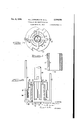
Fig. 1 shows a tube to be plated, the surfaces to be plated being indicated by heavy lines.
Figs. 2-8 show the apparatus.
Fig. 1 shows a tube Hi whose inner surface II and a broad stripe I2 of whose outer surface are to be plated simultaneously, leaving unplated the narrow annular stripes ll of the outer surface.
The support for the tube it] comprises a split ring 20 whose halves are inter-secured by clamp ing bolts 2! and which has supporting rods 22 secured thereto, the ring surrounding the tube Ill at a lower one of the stripes M, the latter thus being blocked ofi by the ring 29. An electric circuit to the tube Ill from any suitable terminal is conducted through either or both supporting rods 22 and the ring 20 which may be of conducting material, such as steel, not soluble in the electrolyte, or it may be of insulating material with a conducting strap'provided thereon to establish a conducting path between the tube H] at stripe l4 and a post 01 rod 22.
When the tube In is disposed within the clamping ring 20 it will project upwardly therefrom as indicated leaving exposed the inner surface H, the stripe l2, and the upper stripe M. The latter may be blocked 011 by any suitable means such as. a rubber band 23 so that only the surfaces H and I! are exposed.
The anode consists of a body 30 in the form --of a steel tube to whose lower end is secured a tube 3| plugged at its lower end by any suitable plug 32. The tube 3| isadapted to contain material with which the tube is to be plated and is formed porous so thatv contact can be made between the electrolyte and the material within tube 3| Formed on tube 3| are blades or paddles 33 for stirring and for circulating the electrolyte.
Clamped to the steel tube 30 by a vsplit clamping ring 35 are several og'ee shaped anode elements 36 whose lower ends 81 project downwardly to be more or less parallel to the axis of tubes HI-30%|, being deflected as indicated to serve as paddles or agitators for the electrolyte.
The elements 35 are in electrical contact with the anode tube 39 where they engage such tube and tube 30 is connected to a terminal to serve as an anode. All except the areas indicated at 38 on the inner lower surfaces of the elements 36-31 are coated with insulation so that inner areas 38 only are in electrical contact with electrolyte. The areas 38 determine the thickness of plating on stripe i2 of tube I0.
I The anode. consisting of tubes 30-31 and elements 36, may be telescoped into and around a tube Ill seated in ring 28 so that the porous tube 3! will face the inner surface I! of tube it and so that areas 38 will face the outer stripe it of tube In with all of the parts shown immersed in electrolyte. With the anode revolving on its axis, and with ordinary plating requirements being met, surfaces H and I2 of the tube it will be electroplated simultaneously.
The work support comprising ring 26 and rods 22 is believed to be a novel work support or arrangement for the purposes herein described.
The addition to the anode of elements 36 permitting simultaneous plating of the inner and outer surfaces of tube Ill is also believed to be new, for whereas anodes consisting of tubes 3il-3l have been used for plating the interior of a tube, it is not believed that such anodes have been equipped with anode elements 38 to permit the outer surfaces l2 to be plated simultaneously with the inner surface H.
Now having described the plating apparatus herein disclosed reference should be had to the claim which follows for a determination of the invention hereof.
I claim: Apparatus for electroplating the inside and outside of a tube simultaneously comprlsing a tube support and an anode assembly, the tube support being of a character to leave exposed the surfaces of the tube to be plated, the anode assembly consisting of a body whose lower end is adapted to be disposed within the upper end of the tube, and supplementary elements secured at the upper end only to said body at a point above the tube and adapted to be disposed around the-upper end ofthe tube outside of it, the anode assembly moving as a unit during the position ing of the tube and the anode assembly for plating.
V RANDOLPHLSTRICKLAND.
HAROLD ZEMON. l
Priority Applications (1)
| Application Number | Priority Date | Filing Date | Title |
|---|---|---|---|
| US479030A US2364564A (en) | 1943-03-13 | 1943-03-13 | Apparatus for electroplating |
Applications Claiming Priority (1)
| Application Number | Priority Date | Filing Date | Title |
|---|---|---|---|
| US479030A US2364564A (en) | 1943-03-13 | 1943-03-13 | Apparatus for electroplating |
Publications (1)
| Publication Number | Publication Date |
|---|---|
| US2364564A true US2364564A (en) | 1944-12-05 |
Family
ID=23902367
Family Applications (1)
| Application Number | Title | Priority Date | Filing Date |
|---|---|---|---|
| US479030A Expired - Lifetime US2364564A (en) | 1943-03-13 | 1943-03-13 | Apparatus for electroplating |
Country Status (1)
| Country | Link |
|---|---|
| US (1) | US2364564A (en) |
Cited By (3)
| Publication number | Priority date | Publication date | Assignee | Title |
|---|---|---|---|---|
| US3477926A (en) * | 1965-05-24 | 1969-11-11 | Eastman Kodak Co | Electrolytic process and apparatus for recovering metals |
| US3507770A (en) * | 1967-12-08 | 1970-04-21 | Charles G Fleming | Apparatus for electrolytic refining of copper |
| US20220090288A1 (en) * | 2019-01-23 | 2022-03-24 | Ppg Industries Ohio, Inc. | System for electrocoating conductive substrates |
-
1943
- 1943-03-13 US US479030A patent/US2364564A/en not_active Expired - Lifetime
Cited By (3)
| Publication number | Priority date | Publication date | Assignee | Title |
|---|---|---|---|---|
| US3477926A (en) * | 1965-05-24 | 1969-11-11 | Eastman Kodak Co | Electrolytic process and apparatus for recovering metals |
| US3507770A (en) * | 1967-12-08 | 1970-04-21 | Charles G Fleming | Apparatus for electrolytic refining of copper |
| US20220090288A1 (en) * | 2019-01-23 | 2022-03-24 | Ppg Industries Ohio, Inc. | System for electrocoating conductive substrates |
Similar Documents
| Publication | Publication Date | Title |
|---|---|---|
| US3065153A (en) | Electroplating method and apparatus | |
| ES8102343A1 (en) | Finned heat transfer tube with porous boiling surface and method for producing same | |
| US4189360A (en) | Process for continuous anodizing of aluminum | |
| US2364564A (en) | Apparatus for electroplating | |
| US1772074A (en) | Method of producing galvanic coatings | |
| US2694040A (en) | Methods of selectively plating p-type material of a semiconductor containing a p-n junction | |
| US2721839A (en) | Plating apparatus for electrical rectifiers | |
| FR2280476A1 (en) | METHOD OF MANUFACTURING AN ELECTRODE FOR THE ELECTROLYTIC MACHINING OF A DRAWING WITH GROOVES IN THE CURVED SURFACE OF A PART | |
| US3616287A (en) | Method for hard-chrome plating large metallic surfaces | |
| US3696017A (en) | Means for electrolytically depositing metal on an object or for anodic oxidation of an object | |
| US3256170A (en) | Electroplating barrel | |
| GB1233102A (en) | ||
| US3282805A (en) | Method of detecting discontinuities in cable conductors | |
| US2362474A (en) | Electroplating apparatus | |
| GB1397139A (en) | Electrical contact | |
| GB1192389A (en) | Electroplating Method and Apparatus | |
| US2972573A (en) | Electrolytic cell | |
| GB1134759A (en) | Improvements in electrolytic machining | |
| SU1426459A3 (en) | Apparatus for applying electroplated metal coating on inner surface of continuous metal strip | |
| US1906378A (en) | Anode support | |
| US3751354A (en) | Electroplating cell including magnetic means to couple concave workpieces to a plating rack | |
| US3888755A (en) | Cylinder plating rack | |
| GB1508826A (en) | Electroplating | |
| Held | Process and Apparatus for Electroplating Strips | |
| SU460151A1 (en) | Device for supplying current to the electrode tool |