US2361663A - Dispensing device - Google Patents
Dispensing device Download PDFInfo
- Publication number
- US2361663A US2361663A US470387A US47038742A US2361663A US 2361663 A US2361663 A US 2361663A US 470387 A US470387 A US 470387A US 47038742 A US47038742 A US 47038742A US 2361663 A US2361663 A US 2361663A
- Authority
- US
- United States
- Prior art keywords
- base
- container
- chain
- orifice
- dispensing
- Prior art date
- Legal status (The legal status is an assumption and is not a legal conclusion. Google has not performed a legal analysis and makes no representation as to the accuracy of the status listed.)
- Expired - Lifetime
Links
Images
Classifications
-
- A—HUMAN NECESSITIES
- A47—FURNITURE; DOMESTIC ARTICLES OR APPLIANCES; COFFEE MILLS; SPICE MILLS; SUCTION CLEANERS IN GENERAL
- A47K—SANITARY EQUIPMENT; ACCESSORIES THEREFOR, e.g. TOILET ACCESSORIES
- A47K5/00—Holders or dispensers for soap, toothpaste or the like
- A47K5/06—Dispensers for soap
- A47K5/10—Dispensers for soap for powdered soap
Definitions
- My invention has to do with dispensers and, in its more particular aspects, relates to devices pe culiarly adaptable for dispensing pulverulent material such as powdered soaps and the like, although the invention is by no means limited to such use.
- Another object is the provision of a dispenser in which the parts in contact with the material are efiectively shielded against becoming wetted.
- Another object is to provide, in such a device, a simple and efiective material agitating means.
- Another object is the provision of a dispenser which may be locked in position.
- Fig. 1 is a front elevation, a part being broken away for illustrative purposes;
- Fig. 2 is a section taken on line 2-2 of Fig. 1;
- Fig. 3 is a vertical section taken on line 33 of Fig. 1;
- Fig. 4 is a bottom plan view, a part being shown in section.
- Fig. 5 is a perspective of the bracket element.
- the numeral 5 denotes the base having a conical hopper portion 6 with a dispensing orifice I through the center, whose outlet end communicates with a surrounding neck 9 whose purpose will be described.
- the bore of neck '9 flares outwardly at and adjacent its lower end it, said bore being of larger diameter than orifice 1 whereby to provide a shoulder l2 of somewhat rounded cross-section.
- a spring member I5 which spring member has a coil I5a and terminates in a relatively long leg [5b.
- Leg I 51) is looped about the inner end of a ball chain ll, whose balls are of a diameter to be passable through but to rather snugly fit the orifice 1 in the manner more particularly described and claimed in the copending application of Vern O. Ring, Serial Number 347,333, filed July 24, 1940, which application matured into Patent No. 2,312,730.
- a closure disc I8 is mounted on the chain at a point spaced from the outer end of the chain, in position to engage shoulder I 2 to eifectively seal the outlet end of the orifice 1 when the device is not being used.
- the outer end of the chain I 1 extends through neck 9 and carries at its outer end a ball [9 to be used as a pull element.
- a container 22 which may be taken as typical, for instance, of a cardboard container of soap powder or the like in which the product is sold by the manufacturer, is detachably mounted on the base by being inverted and having its open end fitted over the base 5 with its peripheral edge wedged in the V groove 2!.
- Cardboard being a relatively easily compressible material, the peripheral edge of the cardboard container readily becomes compressed between the V-walls of the groove to provide an efiective peripheral seal.
- I For mounting the dispenser on a wall W or the like I provide a wall plate 25 which has holes 26 for securing the plate to the wall, as by means of screws 27. I also provide a pair of diagonal holes 28 in the plate in which I mount a pair of diagonally upwardly and outwardly disposed pins 29 which detachably fit into corresponding diagonally-disposed holes 30 in the base 5, said holes opening through the bottom of the base.
- This bracket mounting structure renders it feasible to employ wooden pins 29 since, in this combination, they are capable of supporting all the necessary weight as well as withstanding all the ordinary stresses to which the dispenser is subjected in use. In fact, it is feasible to make the entire base and bracket structure of wood or the like.
- the neck 9 serves the highly useful purpose of preventing any part of the chain which might enter the orifice 1' from being 'wettedby the hand of the user since the neck is preferably substantially as long as the length of travel of the chain during the dispensing operation so that at no time does the wetted hand of the user contact that portion of thechainwhich enters'the orifice.
- the flare ID of the neck 9 is provided to facilitate re-entrance of the disc i8 "into the neck.
- a device for dispensing granular material comprising a container having a base, a dispensing orifice through the base, a dredge chain extending from inside to outside of the container through the orifice and means for resiliently mounting the inner end of the chain, including a spring element having one leg secured to the baseand an opposed leg secured to the inner end of the chain, the outer end of the last-mentioned spring leg being of a length and shape to contact the base upon movement of the chain outwardly through the orifice whereby to halt further outward movement of the chain.
- a device for dispensing granular material comprising, in combination, a base, a container resting on and separable from.
- the base a dispensing orifice through the base, a dredge member extending through the orifice, and means for resiliently supporting the inner end of the dredge member independently of the container, including a spring having one leg secured to the base and a second leg disposed imposition overhanging the orifice, the inner end of the dredge member being secured to the second leg.
Landscapes
- Health & Medical Sciences (AREA)
- Public Health (AREA)
- Containers And Packaging Bodies Having A Special Means To Remove Contents (AREA)
- Closures For Containers (AREA)
Description
IN V EN TOR. 1111! C A STINE DISPENSING DEVICE Filed Dec. 28. 1942 Oct. 31, 1944.
Patented Oct. 31, 1944 I DISPENSING DEVICE Carl A. Stine, Van Nuys, Calif., assignor to Turco Products, Inc., Los Angeles, Calif., a corporation of California Application December 28, 1942, Serial No. 470,387
2 Claims.
My invention has to do with dispensers and, in its more particular aspects, relates to devices pe culiarly adaptable for dispensing pulverulent material such as powdered soaps and the like, although the invention is by no means limited to such use.
Among its principal objects I aim to produce a dispenser which is extremely economical of manufacture and which at the same time is highly efiicient and durable.
It is also among the objects of my invention to provide a dispenser which has a base portion to be stationarily mounted at the place of use while the container in which the product to be dispensed is sold may be used as the container element of the dispensing device and may be readily applied to the base in a manner to seal the container against leakage and exposure of its contents.
Another object is the provision of a dispenser in which the parts in contact with the material are efiectively shielded against becoming wetted.
Another object is to provide, in such a device, a simple and efiective material agitating means.
Another object is the provision of a dispenser which may be locked in position.
Still further advantages are to be derived from my invention and how those as well as the objects hereinabove enumerated are attained will become clear from the following detailed description of one specific form of device in which the invention may be carried out, for which purpose I shall refer to the accompanying drawing, in which:
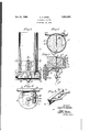
Fig. 1 is a front elevation, a part being broken away for illustrative purposes;
Fig. 2 is a section taken on line 2-2 of Fig. 1;
Fig. 3 is a vertical section taken on line 33 of Fig. 1;
Fig. 4 is a bottom plan view, a part being shown in section; and
Fig. 5 is a perspective of the bracket element.
In the drawing, the numeral 5 denotes the base having a conical hopper portion 6 with a dispensing orifice I through the center, whose outlet end communicates with a surrounding neck 9 whose purpose will be described. The bore of neck '9 flares outwardly at and adjacent its lower end it, said bore being of larger diameter than orifice 1 whereby to provide a shoulder l2 of somewhat rounded cross-section.
In a hole M in the base I mount one leg of a spring member I5, which spring member has a coil I5a and terminates in a relatively long leg [5b. Leg I 51) is looped about the inner end of a ball chain ll, whose balls are of a diameter to be passable through but to rather snugly fit the orifice 1 in the manner more particularly described and claimed in the copending application of Vern O. Ring, Serial Number 347,333, filed July 24, 1940, which application matured into Patent No. 2,312,730. A closure disc I8 is mounted on the chain at a point spaced from the outer end of the chain, in position to engage shoulder I 2 to eifectively seal the outlet end of the orifice 1 when the device is not being used. The outer end of the chain I 1 extends through neck 9 and carries at its outer end a ball [9 to be used as a pull element.
Around base 5 I provide an annular flange 20 whose top surface is provided with an annular groove 2! of somewhat V cross-section. A container 22, which may be taken as typical, for instance, of a cardboard container of soap powder or the like in which the product is sold by the manufacturer, is detachably mounted on the base by being inverted and having its open end fitted over the base 5 with its peripheral edge wedged in the V groove 2!. Cardboard being a relatively easily compressible material, the peripheral edge of the cardboard container readily becomes compressed between the V-walls of the groove to provide an efiective peripheral seal.
For mounting the dispenser on a wall W or the like I provide a wall plate 25 which has holes 26 for securing the plate to the wall, as by means of screws 27. I also provide a pair of diagonal holes 28 in the plate in which I mount a pair of diagonally upwardly and outwardly disposed pins 29 which detachably fit into corresponding diagonally-disposed holes 30 in the base 5, said holes opening through the bottom of the base. This bracket mounting structure renders it feasible to employ wooden pins 29 since, in this combination, they are capable of supporting all the necessary weight as well as withstanding all the ordinary stresses to which the dispenser is subjected in use. In fact, it is feasible to make the entire base and bracket structure of wood or the like.
To look the base on the bracket,-I provide a pair of transverse holes 40 in the base and registering holes 4|, one in each of the pins 29, and insert in each pair of registering holes a pin 43.
These pins prevent the base from being removed from the pins 29 and, inasmuch as the outer ends of the pins 43 are covered by the side wall of the container 22, they are efiectively concealed and would be inaccessible unless the container were removed. Thus the container 22 could not be removed from the base without spilling the contents inasmuch as, in order to remove the filled container without spilling its contents, it is neces sary to first detach the base from the bracket and then reverse the container end for end until the base is at the top thereof.
Assuming the device to be used as a soap dispenser over a wash basin or the like, the user, with the palm of his hand facing upwardly, grasps the outer end of the chain immediately above the ball I!) between the fingers and pulls downwardly against the pressure of spring 15, during which operation the ball chain 11 drags sufiicient of the powdered soap from the container through orifice I and .neck .9, it dropping onto the hand of the user. Release of the chain permits the spring to return the chain to normal position, with the disc l8 engaging shoulder IE to seal the outlet. The movement of the spring arm I51) during those operationsserves effectively to agitate the powder adjacent the discharge orifice and also, during the dispensing operation, the outer end of the arm [5?) will abut the surface "6 of the base (dash line position of Fig. 2) and act as a stop to prevent further outward movement of the chain.
The neck 9 serves the highly useful purpose of preventing any part of the chain which might enter the orifice 1' from being 'wettedby the hand of the user since the neck is preferably substantially as long as the length of travel of the chain during the dispensing operation so that at no time does the wetted hand of the user contact that portion of thechainwhich enters'the orifice. The flare ID of the neck 9 is provided to facilitate re-entrance of the disc i8 "into the neck.
Within its broader scope as defined by the appended claims, the invention is susceptible of being carried out in other specific forms of device and I therefore do not wish to be limited to the specific details hereinabove described except to the extent that some of the claims may recite those specific details.
I claim:
1. A device for dispensing granular material comprising a container having a base, a dispensing orifice through the base, a dredge chain extending from inside to outside of the container through the orifice and means for resiliently mounting the inner end of the chain, including a spring element having one leg secured to the baseand an opposed leg secured to the inner end of the chain, the outer end of the last-mentioned spring leg being of a length and shape to contact the base upon movement of the chain outwardly through the orifice whereby to halt further outward movement of the chain. 2. A device for dispensing granular material comprising, in combination, a base, a container resting on and separable from. the base, a dispensing orifice through the base, a dredge member extending through the orifice, and means for resiliently supporting the inner end of the dredge member independently of the container, including a spring having one leg secured to the base and a second leg disposed imposition overhanging the orifice, the inner end of the dredge member being secured to the second leg.
CARL A. STINE.
Priority Applications (1)
| Application Number | Priority Date | Filing Date | Title |
|---|---|---|---|
| US470387A US2361663A (en) | 1942-12-28 | 1942-12-28 | Dispensing device |
Applications Claiming Priority (1)
| Application Number | Priority Date | Filing Date | Title |
|---|---|---|---|
| US470387A US2361663A (en) | 1942-12-28 | 1942-12-28 | Dispensing device |
Publications (1)
| Publication Number | Publication Date |
|---|---|
| US2361663A true US2361663A (en) | 1944-10-31 |
Family
ID=23867429
Family Applications (1)
| Application Number | Title | Priority Date | Filing Date |
|---|---|---|---|
| US470387A Expired - Lifetime US2361663A (en) | 1942-12-28 | 1942-12-28 | Dispensing device |
Country Status (1)
| Country | Link |
|---|---|
| US (1) | US2361663A (en) |
Cited By (7)
| Publication number | Priority date | Publication date | Assignee | Title |
|---|---|---|---|---|
| US2446967A (en) * | 1944-06-26 | 1948-08-10 | Turco Products Inc | Soap dispenser |
| US2508939A (en) * | 1945-02-12 | 1950-05-23 | Shellmar Products Corp | Dispenser for powdered material |
| US2510657A (en) * | 1948-12-14 | 1950-06-06 | Gilbert & Barker Mfg Co | Liquid sampling device |
| US3140147A (en) * | 1964-07-07 | Scenting device | ||
| US3178255A (en) * | 1962-12-03 | 1965-04-13 | Fragrance Process Company Inc | Air treatment device |
| US3261512A (en) * | 1964-07-22 | 1966-07-19 | Fragrance Process Company Inc | Dispenser utilizing movable bead chain |
| US3441133A (en) * | 1966-05-04 | 1969-04-29 | Mench & Miksits Research & Mfg | Vane control for air classifier |
-
1942
- 1942-12-28 US US470387A patent/US2361663A/en not_active Expired - Lifetime
Cited By (7)
| Publication number | Priority date | Publication date | Assignee | Title |
|---|---|---|---|---|
| US3140147A (en) * | 1964-07-07 | Scenting device | ||
| US2446967A (en) * | 1944-06-26 | 1948-08-10 | Turco Products Inc | Soap dispenser |
| US2508939A (en) * | 1945-02-12 | 1950-05-23 | Shellmar Products Corp | Dispenser for powdered material |
| US2510657A (en) * | 1948-12-14 | 1950-06-06 | Gilbert & Barker Mfg Co | Liquid sampling device |
| US3178255A (en) * | 1962-12-03 | 1965-04-13 | Fragrance Process Company Inc | Air treatment device |
| US3261512A (en) * | 1964-07-22 | 1966-07-19 | Fragrance Process Company Inc | Dispenser utilizing movable bead chain |
| US3441133A (en) * | 1966-05-04 | 1969-04-29 | Mench & Miksits Research & Mfg | Vane control for air classifier |
Similar Documents
| Publication | Publication Date | Title |
|---|---|---|
| US3314426A (en) | Eyecup and spray dispenser | |
| US2628744A (en) | Liquid soap dispenser | |
| US2361663A (en) | Dispensing device | |
| US2193232A (en) | Liquid dispensing device | |
| US2626089A (en) | Powdered and granulated material container with self-closing dispensing valve | |
| US2311330A (en) | Soap dispenser | |
| US2324337A (en) | Massaging appliance | |
| US1886623A (en) | Liquid dispensing apparatus | |
| US2402707A (en) | Dispensing apparatus | |
| US2516703A (en) | Pitcher | |
| US1944447A (en) | Soap dispenser | |
| US2144923A (en) | Funnel support | |
| US2312730A (en) | Dispenser | |
| US2376944A (en) | Paste or cream dispenser | |
| US2134927A (en) | Tack container | |
| US2636208A (en) | Drain receptacle for bottle cleaning shot | |
| US1673617A (en) | Finger ring | |
| US2655290A (en) | Soap dispenser | |
| US2281135A (en) | Dispenser cap | |
| US2137041A (en) | Dispenser | |
| US2849035A (en) | Powdered soap and detergent dispensing device | |
| US2431081A (en) | Powder spray dispenser | |
| US2079364A (en) | Dispensing device | |
| US2763404A (en) | Flexible dispensing container supportable for bottom discharge with internally extending outlet pipe having a trap forming loop | |
| US1932384A (en) | Soap dispenser |