US2355834A - Wood flooring - Google Patents
Wood flooring Download PDFInfo
- Publication number
- US2355834A US2355834A US344352A US34435240A US2355834A US 2355834 A US2355834 A US 2355834A US 344352 A US344352 A US 344352A US 34435240 A US34435240 A US 34435240A US 2355834 A US2355834 A US 2355834A
- Authority
- US
- United States
- Prior art keywords
- blocks
- key
- row
- strips
- strip
- Prior art date
- Legal status (The legal status is an assumption and is not a legal conclusion. Google has not performed a legal analysis and makes no representation as to the accuracy of the status listed.)
- Expired - Lifetime
Links
Images

Classifications
-
- E—FIXED CONSTRUCTIONS
- E04—BUILDING
- E04F—FINISHING WORK ON BUILDINGS, e.g. STAIRS, FLOORS
- E04F15/00—Flooring
- E04F15/02—Flooring or floor layers composed of a number of similar elements
- E04F15/02005—Construction of joints, e.g. dividing strips
- E04F15/02027—Means for spacing the flooring from an adjoining wall
-
- E—FIXED CONSTRUCTIONS
- E04—BUILDING
- E04F—FINISHING WORK ON BUILDINGS, e.g. STAIRS, FLOORS
- E04F15/00—Flooring
- E04F15/02—Flooring or floor layers composed of a number of similar elements
- E04F15/04—Flooring or floor layers composed of a number of similar elements only of wood or with a top layer of wood, e.g. with wooden or metal connecting members
Definitions
- This invention relatesto composite woodblock flooring, to a process'of manufacturing; and to 'a method of handling and laying the same, and
- the invention contemplates and has for its principal objects the provision of improved features in a floor of thisor similar type, and related improvements in the process of m'anufac turing and the methodof handling and laying such floor unitswhereby the finished floor will be laid level, will remain level, and will not be apt to buckle from expansion of the blocks due tomoisture. d
- Another object of this invention is to provide a method wherebythe flooring unitstr-ipscan be cheaply and efiiciently manufactured, and the flooring can be shipped'in bundles of unit strips and easily laid to produce,.a. finished floor.
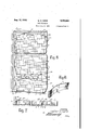
- Fig. 1 is a, broken-away perspective view showing portions of two strips in a finished floor
- Fig. 2 is a perspective view of an upright unit strip
- Fig. 3 is a si ilar,but upside down, perspective View showing the underside oi-this strip
- Fig. 4 is a section-taken onthe line 4-4 of Fig.3.
- Fig. 6 is a perspective view .showing'a unit-"of apairofsprings
- Fig. 7 is a sectional view taken along the line
- Rectangular, Wooden blocks lare cut-to present their end grain for wear, so that th e grain of these blocks is substantially vertical when the blocks are in the floor.
- 'Narr'owsplin slots 2 extendinto each outer side of 'the bloc'ks, as
- slots 2 are preferablylocatedbelow the middle, orclosertothe' bott nig'of these blocks to increase the'depth available'fo'rwearfi Slots 2 receive long, tl1in,springy'metal splines '3'which are fitted into the coiresponding slots of adjacent rows of blocks with moderate looseness or free slidability, so thatthe splines will hold adjacent rows of blocks from relative tilting or vertical displacements and yet will permit the blocks of the several rows to partake of free longitudinal movements along the splines upon expansion due to moisture. This will prevent buckling or warping of the floor, since the expansion can be transmitted along the row s of blocks to take up all clearances and 'finally'to theedge expansion joints;
- a key-way groove or dowel opening 4 having a wider inner portion 4a, extends across and through the central bottom portion of each block 'I and along the row of blocks or each strip.
- the wider inner portion 4a of this'key-way provides shoulders to prevent the blocks from coming off the correspondingly shaped key or dowel 5, which is freely or rather loosely fitted into the key-way to hold all of the blocks of a strip position and yet to'permit longitudinal sliding movements of the blocks on the key 5 upon expansion, to thus prevent buckling.
- the lower corners or sharp shoulders 6 of this key-way groove are adapted to engage in the mastic 8 in which the blocks are laid, and thus they aid in holding the blocks'against lateral movements.
- the lowerside corners ofithe blocks are cut away at 6a to provide-upwardly extending openings to receive mastic between adjacent rows of blocksl l T 'l
- the blocks] are assembled in suitable unit lengths upon the wooden dowels or keys 5 of the same length. It will be apparent that the non-circular key 5 holds the blocks against relativet'iltingj or lateral movements but does not hold themegama longitudinal movements.
- key 5 is of smaller depth than the key-way 4 4a so that it does not en- 'tirely fill thekey-way and thus'leavesa lowerrepping and handling.
- these blocks are laid on the concrete sub-floor 9 on a suitable layer of mastic 8.
- This mastic may be, for example, a suitably prepared, hot or cold asphaltic cement which retains its elasticity and forms a waterproof seal holding the bottoms of the blocks.
- the blocks are cut from long lengths of socalled two-by-fours of yellow pine which have been previously dried and kiln-dried to less than eight percent moisture. These two-by-fours grain ha approximately fifty percent less expansion, due to moisture or the like, than would occur if the key were made of a fiat-sawn strip having the grain running lengthwise and across the key. Thus, the key 5 will have but little lateral expansion which would cause it to grip tightly the sides of key-way 4-411 and prevent free sliding or, if excessive, to possibly split the end-grain blocks.
- the cut blocks are carried on a belt, with the .end grain up, into-the throat of the key-way cutting machine. While on this belt, the blocks-are inspected and defectives removed..
- the key-way cutting machine forms the;;T-shaped--cut across the bottom side ofeach block, and the blocks l are then automatically fitted and slid onto the key -5 which isheld in place until the last block goes on. These strips are preferably about six feet long. The complete strip isthen moved to one,
- the strip is now carried by a belt into a molding machine, the upper-and lower cutters of which true and finish the upper and lower surfaces of the' blocks, the lower surface being only squared off or finished roughly.
- the lower corners 6a are cut off, saws of the proper width cut in the spline groove 2, and the sides of the strip are tapered in-slightly towards the bottom so that the blocks, when laid, will be sureto join at their tops.
- the key. 5 is cut from suitable-strips and is made with .edge
- the floor is laid as follows:
- the mastic a suitable bituminous or asphaltic cement
- a dry concrete sub-floor which has been waterproofed, if necessary, and treated with a suitable bituminous primer.
- the workman removes one nail from one end of each strip, leaving each individual block free on the dowel.
- Both nails may be removed if desired, but if the workman removes only one nailof each strip, he
- An expansion joint such as a two inch strip of, treated cork, is used all the way aroundv the edge of the roomor flooring, and a complete row of strips is laid end-to-end entirely across one edge or side of the fioor.
- the metal spline 3 which is preferably a flexible band oftempered steel suitably galvanized and about one-half inch wide'by four -hundredths of an inch thick, is fitted easily or rather loosely into the slot 2 along the full length of the row of strips from one side of the room to the other. Light taps with a hammer may be used to put the spline into the slot.
- the spline 3 is used in a coil or a continuous roll which is preferably-mounted on a simple reel for easy handling. This reel II is shown in use in Fig. 1. The end of the metal strip 3 is cut off when it has been laid the full length of the row ofxunitstrips.
- next row of units is'laid with its corresponding slot 2 fitting over the protruding portion of the spline 3, as shown in Fig. 1.
- the several rows of strips are laid in break joint fashion; that is, with the joints between strips in one row overlapped by the inter- .mediate portion of a strip ID of adjacent rows.
- the strips can be readily cut into shorter lengths by sawing off dowel 5 and also splitting blocks 'floor or other equivalent area. parent, these springs may, if desired, be employed side or left of Fig. 5.
- the springs Upon dry conditions causing shrinkage of the blocks, the springs will gradually expand andi push the individual blocks and the unit strips together and thus prevent the formation of openings or cracks which would otherwiseappear between the strips and blocks.
- 'Wooden strips 21 maybe laid against walls I! l and I8, and springs 13 preferably have their center portions acting against these. iwooden strips 21; or they may be in reverse position if desired. Referring to the left-hand edge of Fig.5,
- each endof eachof the suitably spaced springs l3 will rest on only one block ingly, I may employ a strip such as IE or, as shown, I may provide a unit strip turned perpendicular to the length of the rest of the strips so that it lays across-their lengths, as shown in 10a. key 5, will act like thestrip l6 and will'transmit pressure from the spring to a plurality of the strips l0. r
- transversely laid unit strips lfla are employed in the same way as shown and described in connection with the top portion of Fig. 5.
- the open spaces formed at the edges of the floor are covered by a suitably secured metal or wood covering plate 24-.
- the wooden, T-shaped key or dowel 5 is so positioned that it is not apt to receive any appreciable quantities of' moisture and cause it to expand and tightly grip or split the blocks.
- the key 5 is well-below the center of the blocks so that moisture from above would have to penetrate through most of the thickness of the blocks to reach it.
- the lower surface of the blocks is sealed in by the mastic, and. moisture is not apt to come through the sides of theblocks.
- the metal splines 3 are quite thin andrequire only a narrow cut or slot 2. Thus they do not unduly weaken the blocks. Since the splines are of metal, they do not expand due to moisture,
- each end of the spring unit l3 will act upon the end of only one strip l0. Accord-.
- the blocks will not tend to grip the spline under moist conditions. Further, it will be noted that the metal splines are buried in insulating wood which reduces expansion of the metal spline itself -due to heat.
- Wooden flooring comprising, a row of end grainbiocks eachhaving an opening therethrough and an elongated wooden keymember with its'grain extending longitudinally and also vertically to give edge grain for small lateral expansion slidably fitting through the openings of 'saidrow to position'its blocks but to permit them to shift longitudinally thereon upon expansion,
- openings and key being formed so that they lit-closely but slidably from side to side but loosely from top to bottom to provide space for vertical expansion of said key.
- unitfiooring strip comprising a row of Wooden blocks each having a longitudinally extending opening therethrough, a wooden dowel extending the length of said strip and readily slidable in each of said openings to hold all of said-blocks a'g'ain'st relative lateral displacements, and two meahseach comprising a recess and a fastening means Wholly countersunk therein to avoid interfere'n'ce with 'or catching on other articles and at least oneof's'aid fastening means being only partly fastenedin and hence readily removable, securing each end block to said dowel against longitudinal movement thereon,- so that all or said blocks are held in a unit strip for shipping and handling and the countersunk but read-1y removable fastening means may be removed during laying to permit free longitudinal block movements due to expansion in the floor.
- a unit strip of wooden, flooring blocks adapt ed to be laid in mastic and comprising a row' of blocks each having a non-circular key-way groove across its bottom face, a 10ng, correspondingly shaped, wooden key member of less depth than said grooves slidably received and countersunk therein to hold said blocks against relative tilting or lateral movements and to provide a lower,
- each upright side of each strip having a narrow, horizontal, inwardly extending slot, and continuous splines comprising bands of thin, flat metal slidably mountedin the slots of adjacent strips to prevent :relative vertical movements of said strips, each spline band extending along a plurality of strips from one side of the fioor to the other.
- Wooden flooring comprising a plurality of side-by-side rows of end grain wooden blocks, each block of a row having a keyway of polygonal cross section extending across its bottom face in a direction longitudinally of the row, said keyways cooperating to form a continuous keyway throughout the length of the row, an elongated wooden key-member having a polygonal cross sectioncorresponding generally to the polygonal cross section of said keywayand' loosely fitted'and lying wholly within said continuous keyway in such manner that each wooden 'block of the row is readily slidable'on said key member but is prevented from relative rotary or tilting displacement thereon, the upright, exposed opposite sides of the blocks along each row having slots extending longitudinally of the row and cooperating to form continuous slots on each side of the row throughout its length, and resilient metal splines extending along each side of each row and being slidably fitted in opposed slots of adjacent rows to permit longitudinal shifting of blocks in each 'rowbut to resilientlyretain rows of blocks against vertical or tilting displacement in the
- Wooden flooring comprising a plurality of side-by-side rows of .end' grain wooden blocks, each block of a row havinga keyway of upright T-shaped cross section extending across its bottom face in a direction longitudinally of the row, said keyways cooperating to'form a continuous keyway throughout the length'of. the.
- each wooden block of the row is readily slidable on said key member but is prevented from relative rotary or tilting displacement thereon
- the upright, exposed opposite sides of the blocks along each row having slots extending longitudinally of the row and 00- operating to form continuous slots on each side oi -the. row throughout its length, and resilient metal splines extending along each side of each row and being. slidably fitted in opposed slots of adjacent rows to permit longitudinal shifting of blocks in-cach row but to resiliently retain rows of blocks against vertical or tilting displacement in the: floor.
Landscapes
- Engineering & Computer Science (AREA)
- Architecture (AREA)
- Civil Engineering (AREA)
- Structural Engineering (AREA)
- Life Sciences & Earth Sciences (AREA)
- Wood Science & Technology (AREA)
- Floor Finish (AREA)
Description
w. e. W EBB WOOD FLOORING Aug. 15, 1944,
F'i-led July 8, 1940 2 Sheets-Sheet l 1G A w I h Aug. 15, 1944.- l w, WEBB 2,355,834
woon FLOORiNG Filed July 8, 1940 2 Sheets-Sheet 2 I waiter Patented Aug. 15, 1944 UNITED I WOOD FLOORING 7 Walter G. Webb, Detroit, Mich, assignor to Evans Products; Company,
\ corporation of Delaware Detroit, l Mich, a
" Application'Ju ly 8, 1940, Serial No. 344,352
I 8 Claims.
This invention relatesto composite woodblock flooring, to a process'of manufacturing; and to 'a method of handling and laying the same, and
in particular to flooring of end-grain blocks preferably assembled and held in unitstripsfor finishing,,handling and laying.
Generally, the invention contemplates and has for its principal objects the provision of improved features in a floor of thisor similar type, and related improvements in the process of m'anufac turing and the methodof handling and laying such floor unitswhereby the finished floor will be laid level, will remain level, and will not be apt to buckle from expansion of the blocks due tomoisture. d
[Another object of this invention is to provide a method wherebythe flooring unitstr-ipscan be cheaply and efiiciently manufactured, and the flooring can be shipped'in bundles of unit strips and easily laid to produce,.a. finished floor.
Other objects and advantages 'of this invention will readily become apparent through a reading ofthe following detailed description and the ac,-
companyingdrawings, in which:
Fig. 1 is a, broken-away perspective view showing portions of two strips in a finished floor, and
indicating the spline reel used in laying the flooring. v i
Fig. 2 is a perspective view of an upright unit strip, I
Fig. 3 is a si ilar,but upside down, perspective View showing the underside oi-this strip, and
Fig. 4 is a section-taken onthe line 4-4 of Fig.3.
Fig. 5'is a brokeneaway'plan viewrshowinga number of strips, as laid in a room'. floor, and their side splines,=- 1 .1
Fig. 6 is a perspective view .showing'a unit-"of apairofsprings, and 1 Fig. 7 is a sectional view taken along the line Referring now to the drawings in-detail,-in which like reference characters indicate lik parts throughout the several views? Rectangular, Wooden blocks lare cut-to present their end grain for wear, so that th e grain of these blocks is substantially vertical when the blocks are in the floor. 'Narr'owsplin slots 2 extendinto each outer side of 'the bloc'ks, as
shown. These slots 2 are preferablylocatedbelow the middle, orclosertothe' bott nig'of these blocks to increase the'depth available'fo'rwearfi Slots 2 receive long, tl1in,springy'metal splines '3'which are fitted into the coiresponding slots of adjacent rows of blocks with moderate looseness or free slidability, so thatthe splines will hold adjacent rows of blocks from relative tilting or vertical displacements and yet will permit the blocks of the several rows to partake of free longitudinal movements along the splines upon expansion due to moisture. This will prevent buckling or warping of the floor, since the expansion can be transmitted along the row s of blocks to take up all clearances and 'finally'to theedge expansion joints;
A key-way groove or dowel opening 4, having a wider inner portion 4a, extends across and through the central bottom portion of each block 'I and along the row of blocks or each strip. The wider inner portion 4a of this'key-way provides shoulders to prevent the blocks from coming off the correspondingly shaped key or dowel 5, which is freely or rather loosely fitted into the key-way to hold all of the blocks of a strip position and yet to'permit longitudinal sliding movements of the blocks on the key 5 upon expansion, to thus prevent buckling. I e
The lower corners or sharp shoulders 6 of this key-way groove are adapted to engage in the mastic 8 in which the blocks are laid, and thus they aid in holding the blocks'against lateral movements. Also, the lowerside corners ofithe blocks are cut away at 6a to provide-upwardly extending openings to receive mastic between adjacent rows of blocksl l T 'l As shown in Figs. 2 and3, the blocks] are assembled in suitable unit lengths upon the wooden dowels or keys 5 of the same length. It will be apparent that the non-circular key 5 holds the blocks against relativet'iltingj or lateral movements but does not hold themegama longitudinal movements. Accordingly, the ends of the key '5- are removably secured; to the' endblocks by nails '1 to prevent suchlongitudinal movej m'ent's; until the strips are laid in the floor. 1 It will be noted that key 5 is of smaller depth than the key-way 4 4a so that it does not en- 'tirely fill thekey-way and thus'leavesa lowerrepping and handling.
As shown in Fig. 1, these blocks are laid on the concrete sub-floor 9 on a suitable layer of mastic 8. This mastic may be, for example, a suitably prepared, hot or cold asphaltic cement which retains its elasticity and forms a waterproof seal holding the bottoms of the blocks.
As shown in Figs. 2 and 3, the unit strips of blocks are represented as a whole by numeral H].
In the following descriptionof the manufacture and installation of'this flooring, certain preferred dimensions and other details are given by way of example only, and it will be understood that other sizes are and can be used.
In the manufacture of this flooring at the factory, the blocks are cut from long lengths of socalled two-by-fours of yellow pine which have been previously dried and kiln-dried to less than eight percent moisture. These two-by-fours grain ha approximately fifty percent less expansion, due to moisture or the like, than would occur if the key were made of a fiat-sawn strip having the grain running lengthwise and across the key. Thus, the key 5 will have but little lateral expansion which would cause it to grip tightly the sides of key-way 4-411 and prevent free sliding or, if excessive, to possibly split the end-grain blocks. The greater expansion of the key in a vertical direction is readily taken care of by the extra space or recess underneath the key and also by forming the upper, longitudinal portion 4a of the key-way a little bit deeper than the depth of are, of course, rough and not exactly this size in inches. These lengths go through a surfacing machine which finishes all four sides to give them final dimensions of-1%" by 3%". They then go to the cut-off saws which cut them into lengths of approximately thirty inches. These shorter lengths go to a gang saw which simultaneously cuts them into blocks or lengths of about 2%, which dimension will be the thickness of the blocks in the flooring when laid.
The cut blocks are carried on a belt, with the .end grain up, into-the throat of the key-way cutting machine. While on this belt, the blocks-are inspected and defectives removed.. The key-way cutting machine forms the;;T-shaped--cut across the bottom side ofeach block, and the blocks l are then automatically fitted and slid onto the key -5 which isheld in place until the last block goes on. These strips are preferably about six feet long. The complete strip isthen moved to one,
sideso that the operation may be repeated.
These unit strips I arenow turned upside down and the nails 1 put through the ends of the key to fix the end blocks. v T
It will be noted that the blocks of the strips [8 now have unfinished top and bottom surfaces.
The strip is now carried by a belt into a molding machine, the upper-and lower cutters of which true and finish the upper and lower surfaces of the' blocks, the lower surface being only squared off or finished roughly. At the same time, or while thestrips are held fixed, the lower corners 6a are cut off, saws of the proper width cut in the spline groove 2, and the sides of the strip are tapered in-slightly towards the bottom so that the blocks, when laid, will be sureto join at their tops.
Note that duringall: these substantially simultaneous finish operations all the blocks of the unit strip are held aligned and in fixed position by, "and'with respect to, the key 5. Since 'these operations are performed together, the spline cuts 2 and also the bottom faces of the blocks will be accurately spaced with respect to thefinished top surfaces. This is-very important in this type of flooring. Accordingly, the blocks, when laid in the floor and held by; the splines 3,-presentan even top surface and will -1'iot-require expensive finishing in place. if
Further; it will .be noted that the removable nails 1 hold the blocks together to go into the molding and sawing machine or machines without danger-of catching, since they are within the recess at the bottom of key-way 4.
As shownin the several figures, the key. 5 is cut from suitable-strips and is made with .edge
grain; that is, the grain runs along the length and up and down or vertical in the strip, This edge the upper or cross portion of the T-shaped key member.
I The details or precise form of the apparatus and machines mentioned herein form no part of the present invention, and it is intended that any of the commercially available machines may be used, as will be well understood by those skilled in this art.- l
The floor is laid as follows:
The mastic, a suitable bituminous or asphaltic cement, is laid on a dry concrete sub-floor which has been waterproofed, if necessary, and treated with a suitable bituminous primer. The workman removes one nail from one end of each strip, leaving each individual block free on the dowel.
Both nails may be removed if desired, but if the workman removes only one nailof each strip, he
.can lift each strip with its loose end up. The one loose, end block will be sufficient to give all the blocks the required longitudinal freedom of movewith their removably fastened end blocks, will save time and produce a well-laid floor.
An expansion joint, such as a two inch strip of, treated cork, is used all the way aroundv the edge of the roomor flooring, and a complete row of strips is laid end-to-end entirely across one edge or side of the fioor. Thenjthe metal spline 3, which is preferably a flexible band oftempered steel suitably galvanized and about one-half inch wide'by four -hundredths of an inch thick, is fitted easily or rather loosely into the slot 2 along the full length of the row of strips from one side of the room to the other. Light taps with a hammer may be used to put the spline into the slot. 1}
The spline 3 is used in a coil or a continuous roll which is preferably-mounted on a simple reel for easy handling. This reel II is shown in use in Fig. 1. The end of the metal strip 3 is cut off when it has been laid the full length of the row ofxunitstrips.
In like fashion, the next row of units is'laid with its corresponding slot 2 fitting over the protruding portion of the spline 3, as shown in Fig. 1. Preferably, the several rows of strips are laid in break joint fashion; that is, with the joints between strips in one row overlapped by the inter- .mediate portion of a strip ID of adjacent rows.
The strips can be readily cut into shorter lengths by sawing off dowel 5 and also splitting blocks 'floor or other equivalent area. parent, these springs may, if desired, be employed side or left of Fig. 5.
of treated cork, I prefer to use springsacting on at least two of the adjacent sides of the room As will be ap on opposite sides or on all four sides; or elseonly 'upon the two sides which are adjacent atfa corner.
While these springs may be ofa'nyproved-for suitable type within the purview'of this invention, I prefer springs of the type shownby l3in- Fig. 6 and comprisingtwo bent flat-type springs l4 suitably secured together by-clip I5 to form a pair acting in parallel. As will be seen in the upper portion of Fig. 5, and'considered'with the Cforegoing disclosure,the plurality of blocks 1 of each unit strip I is freely slidable along its key and its side splines 3 tothus permit free expansion of the blocks due to moist conditions without causing buckling. This expansion, which may take place without breaking the bond to the floor through the elastic mastic, will add up to a considerable amount over a long length of floor taken along the length of strips It), as shown in Fig. 5, so that in practice it may compress the springs I3 shown at the topof Fig. 5 from a 'widthof about 1 /2 down to about A,! inextreme cases. a l l l l In addition, the blocks l of the unit strips ID will expand sideways of the lengthof the strips, and. this expansion is taken upby compressing the springs l3 shown along the side or at the left of Fig. 5. As will be apparent, the resilient resistance of these springs acting against expansion due to moisture, will hold the individual blocks and the several strips [0 tightly together.
Upon dry conditions causing shrinkage of the blocks, the springs will gradually expand andi push the individual blocks and the unit strips together and thus prevent the formation of openings or cracks which would otherwiseappear between the strips and blocks.
i It will be apparent that there is a useful co Referring in detail to- Figs. 5 and 6, the unit strips I0 are laid in break-joint fashion, as mentioned above, with their lengths parallel .to the wall l8 of the room or other space "and perpendicular to the adjacent wall, or the like, ,IT.
'Wooden strips 21 maybe laid against walls I! l and I8, and springs 13 preferably have their center portions acting against these. iwooden strips 21; or they may be in reverse position if desired. Referring to the left-hand edge of Fig.5,
it willbe seen that each endof eachof the suitably spaced springs l3 will rest on only one block ingly, I may employ a strip such as IE or, as shown, I may provide a unit strip turned perpendicular to the length of the rest of the strips so that it lays across-their lengths, as shown in 10a. key 5, will act like thestrip l6 and will'transmit pressure from the spring to a plurality of the strips l0. r
In cases where a large floor area is covered or where the floor is particularly long in one direction, I prefer to provide intermediate expansion joints, as indicated in the lower broken-away portion of Fig. 5 wherein the wooden filler strip l9 isattached to the concrete floor 9 byconventional concrete nails or expansion screws which are well-known and hence not illustrated herein. The springs [3 act against this strip l9 as. they do against the side strips 21. The suitable wood or metal cover plate 2| is secured to strip l9 by screws 22 or other suitable means.
As shown, transversely laid unit strips lfla are employed in the same way as shown and described in connection with the top portion of Fig. 5. The open spaces formed at the edges of the floor are covered by a suitably secured metal or wood covering plate 24-.
After the floor is laid, it is brushed clean, sanded, and'finished with a coat of penetrating sealer. r r
It will be apparent that the wooden, T-shaped key or dowel 5 is so positioned that it is not apt to receive any appreciable quantities of' moisture and cause it to expand and tightly grip or split the blocks. The key 5 is well-below the center of the blocks so that moisture from above would have to penetrate through most of the thickness of the blocks to reach it. The lower surface of the blocks is sealed in by the mastic, and. moisture is not apt to come through the sides of theblocks.
The metal splines 3 are quite thin andrequire only a narrow cut or slot 2. Thus they do not unduly weaken the blocks. Since the splines are of metal, they do not expand due to moisture,
' and thus will not tend to break oif the rather I, and the space between these ends andbe'tween the springs spans'a number of blocks. According1y,'I provide alight strip such as. IE which has a certain amount of inherent springiness or bendabil'ity but will cause one spring unit l3 to act upon a plurality of the individual blocks l.
Similarly, it will be seen from the upper end of Fig. 5 that each end of the spring unit l3 will act upon the end of only one strip l0. Accord-.
easily split sides of the end-grain blocks, asoften happens with the larger,- wooden, side splines. Another disadvantage of the larger, wooden, side splines is that when they shrink due to dryness they permit the blocks to tilt or cant under load and thus make the floor uneven. a
Since the end-grain yellow pine does not expand much lengthwise of the grain, the blocks will not tend to grip the spline under moist conditions. Further, it will be noted that the metal splines are buried in insulating wood which reduces expansion of the metal spline itself -due to heat.
. Thus, it will be apparent that these thin, flat, elastic splines will hold all of the blocks level and will transmit load from one row of blocks to the other. In addition, the fact that the thin splines are'continuous holds the end-to-rnd strips level, prevents wasting of spline'lengths, prevents injury to the spline band since it can be handled in a roll or on a reel, and makes possible an efficient 'method' of laying the floor. The continuous, elastic, thin, springy steel band 3 eifectively transmits load from row to row and between-the strips of a row.
1 It will also 'be' a'pparent'that the individual blocks are longitudinally removable or slidable on both the key. 5 and the splines 3 to permit ex- .pansion without; buckling. a
Thus, this unit strip, and particularly its out the above methods without departing from the scope'of this invention, it is intended. that the-above specific description and. illustration shall be interpreted as purely illustrative and not in a limiting sense. It will be apparent to those skilled in'ttheart that various "changes in the form or in the uses for the above features and methods may be made within the purview of this invention; the scope of which is commensuratewith'. the appended claims; -Ic1aim:.
said openings and key being formed so that they lit-closely but slidably from side to side but loosely from top to bottom to provide space for vertical expansion of said key.
- 2.'A s an article of manufacture, an elongated,
unitfiooring strip comprising a row of Wooden blocks each having a longitudinally extending opening therethrough, a wooden dowel extending the length of said strip and readily slidable in each of said openings to hold all of said-blocks a'g'ain'st relative lateral displacements, and two meahseach comprising a recess and a fastening means Wholly countersunk therein to avoid interfere'n'ce with 'or catching on other articles and at least oneof's'aid fastening means being only partly fastenedin and hence readily removable, securing each end block to said dowel against longitudinal movement thereon,- so that all or said blocks are held in a unit strip for shipping and handling and the countersunk but read-1y removable fastening means may be removed during laying to permit free longitudinal block movements due to expansion in the floor.
1 within said recess extending through each end of said member and fixing it to the end blocks, one of said means being readily removable.
4. A strip of Wooden, flooring blocks adapted Y to be "laid in mastic and comprising a row of blocks each having a key-way groove across its lower face, a long, wooden key slidably fitting in the grooves of said row but being of smaller depth and countersunk therein to provide a lower, mastic-engaging groove and means, at least one being readily removable, securing said key to each end block and each being shoulders, and
' partially driven-in to bereadily removed positioned wholly within said mastic-engaging groove. 4
5. A unit strip of wooden, flooring blocks adapt ed to be laid in mastic and comprising a row' of blocks each having a non-circular key-way groove across its bottom face, a 10ng, correspondingly shaped, wooden key member of less depth than said grooves slidably received and countersunk therein to hold said blocks against relative tilting or lateral movements and to provide a lower,
mastic-engaginggroove for each block under said key member, and a nail through each endor. said vkeymember into'each end block to hold said blocks against longitudinal movements on said key member during handling, the head of each nail being completely within said mastic-engaging groove to avoid catching during handling,.or the like, and at least one of said nails being only prior to laying. q 6,-A composite wooden floor comprisinga plurality ofside-by-side rows of unit strips, each strip. comprising a row of end-grain blocks having a longitudinally extending, non-circular, .wooden key slidably fitting in said opening and extending, the. length of said. strip, each upright side of each strip having a narrow, horizontal, inwardly extending slot, and continuous splines comprising bands of thin, flat metal slidably mountedin the slots of adjacent strips to prevent :relative vertical movements of said strips, each spline band extending along a plurality of strips from one side of the fioor to the other.
7-. Wooden flooring comprising a plurality of side-by-side rows of end grain wooden blocks, each block of a row having a keyway of polygonal cross section extending across its bottom face in a direction longitudinally of the row, said keyways cooperating to form a continuous keyway throughout the length of the row, an elongated wooden key-member having a polygonal cross sectioncorresponding generally to the polygonal cross section of said keywayand' loosely fitted'and lying wholly within said continuous keyway in such manner that each wooden 'block of the row is readily slidable'on said key member but is prevented from relative rotary or tilting displacement thereon, the upright, exposed opposite sides of the blocks along each row having slots extending longitudinally of the row and cooperating to form continuous slots on each side of the row throughout its length, and resilient metal splines extending along each side of each row and being slidably fitted in opposed slots of adjacent rows to permit longitudinal shifting of blocks in each 'rowbut to resilientlyretain rows of blocks against vertical or tilting displacement in the floor.
8; Wooden flooring comprising a plurality of side-by-side rows of .end' grain wooden blocks, each block of a row havinga keyway of upright T-shaped cross section extending across its bottom face in a direction longitudinally of the row, said keyways cooperating to'form a continuous keyway throughout the length'of. the. row, 'an elongated wooden key'member having an upright T-sh-apedcross section corresponding generally to the cross section of said keyway and loosely fitted and lying wholly within said continuous keyway in such manner that each wooden block of the row is readily slidable on said key member but is prevented from relative rotary or tilting displacement thereon, the upright, exposed opposite sides of the blocks along each row having slots extending longitudinally of the row and 00- operating to form continuous slots on each side oi -the. row throughout its length, and resilient metal splines extending along each side of each row and being. slidably fitted in opposed slots of adjacent rows to permit longitudinal shifting of blocks in-cach row but to resiliently retain rows of blocks against vertical or tilting displacement in the: floor.
" WALTER G. WEBB.
Priority Applications (1)
| Application Number | Priority Date | Filing Date | Title |
|---|---|---|---|
| US344352A US2355834A (en) | 1940-07-08 | 1940-07-08 | Wood flooring |
Applications Claiming Priority (1)
| Application Number | Priority Date | Filing Date | Title |
|---|---|---|---|
| US344352A US2355834A (en) | 1940-07-08 | 1940-07-08 | Wood flooring |
Publications (1)
| Publication Number | Publication Date |
|---|---|
| US2355834A true US2355834A (en) | 1944-08-15 |
Family
ID=23350178
Family Applications (1)
| Application Number | Title | Priority Date | Filing Date |
|---|---|---|---|
| US344352A Expired - Lifetime US2355834A (en) | 1940-07-08 | 1940-07-08 | Wood flooring |
Country Status (1)
| Country | Link |
|---|---|
| US (1) | US2355834A (en) |
Cited By (13)
| Publication number | Priority date | Publication date | Assignee | Title |
|---|---|---|---|---|
| US3174411A (en) * | 1960-04-25 | 1965-03-23 | Snecma | Floorings for taking-off and landing |
| US6761008B2 (en) * | 1999-12-14 | 2004-07-13 | Mannington Mills, Inc. | Connecting system for surface coverings |
| US20060179741A1 (en) * | 2005-02-03 | 2006-08-17 | Thomas Sohm | Unknown |
| WO2007070910A1 (en) * | 2005-12-22 | 2007-06-28 | Neuhofer Franz Jun | Laying aid for a floor covering |
| US20080315065A1 (en) * | 2007-06-22 | 2008-12-25 | Hanson Troy A | Bracket assembly for facilitating the installation of a concrete wall on a concrete footing and a method of forming the wall |
| US20110088349A1 (en) * | 2007-06-22 | 2011-04-21 | Hanson Troy A | Bracket assembly for facilitation the installation of a concrete wall on a concrete footing and a method of forming the wall |
| US9222267B2 (en) | 2006-01-12 | 2015-12-29 | Valinge Innovation Ab | Set of floorboards having a resilient groove |
| US9249581B2 (en) | 2009-09-04 | 2016-02-02 | Valinge Innovation Ab | Resilient floor |
| US10059084B2 (en) | 2014-07-16 | 2018-08-28 | Valinge Innovation Ab | Method to produce a thermoplastic wear resistant foil |
| USD845515S1 (en) * | 2017-03-22 | 2019-04-09 | Redland Brick Inc. | Brick tile |
| US10486399B2 (en) | 1999-12-14 | 2019-11-26 | Valinge Innovation Ab | Thermoplastic planks and methods for making the same |
| US10975580B2 (en) | 2001-07-27 | 2021-04-13 | Valinge Innovation Ab | Floor panel with sealing means |
| US11725395B2 (en) | 2009-09-04 | 2023-08-15 | Välinge Innovation AB | Resilient floor |
-
1940
- 1940-07-08 US US344352A patent/US2355834A/en not_active Expired - Lifetime
Cited By (19)
| Publication number | Priority date | Publication date | Assignee | Title |
|---|---|---|---|---|
| US3174411A (en) * | 1960-04-25 | 1965-03-23 | Snecma | Floorings for taking-off and landing |
| US6761008B2 (en) * | 1999-12-14 | 2004-07-13 | Mannington Mills, Inc. | Connecting system for surface coverings |
| US10486399B2 (en) | 1999-12-14 | 2019-11-26 | Valinge Innovation Ab | Thermoplastic planks and methods for making the same |
| US10975580B2 (en) | 2001-07-27 | 2021-04-13 | Valinge Innovation Ab | Floor panel with sealing means |
| US20060179741A1 (en) * | 2005-02-03 | 2006-08-17 | Thomas Sohm | Unknown |
| WO2007070910A1 (en) * | 2005-12-22 | 2007-06-28 | Neuhofer Franz Jun | Laying aid for a floor covering |
| US10450760B2 (en) | 2006-01-12 | 2019-10-22 | Valinge Innovation Ab | Floorboards comprising a decorative edge part in a resilient surface layer |
| US11702847B2 (en) | 2006-01-12 | 2023-07-18 | Valinge Innovation Ab | Floorboards comprising a decorative edge part in a resilient surface layer |
| US11066836B2 (en) | 2006-01-12 | 2021-07-20 | Valinge Innovation Ab | Floorboards comprising a decorative edge part in a resilient surface layer |
| US9222267B2 (en) | 2006-01-12 | 2015-12-29 | Valinge Innovation Ab | Set of floorboards having a resilient groove |
| US9765530B2 (en) | 2006-01-12 | 2017-09-19 | Valinge Innovation Ab | Floorboards comprising a decorative edge part in a resilient surface layer |
| US20080315065A1 (en) * | 2007-06-22 | 2008-12-25 | Hanson Troy A | Bracket assembly for facilitating the installation of a concrete wall on a concrete footing and a method of forming the wall |
| US8348226B2 (en) | 2007-06-22 | 2013-01-08 | Hanson Troy A | Bracket assembly for facilitation the installation of a concrete wall on a concrete footing and a method of forming the wall |
| US20110088349A1 (en) * | 2007-06-22 | 2011-04-21 | Hanson Troy A | Bracket assembly for facilitation the installation of a concrete wall on a concrete footing and a method of forming the wall |
| US9249581B2 (en) | 2009-09-04 | 2016-02-02 | Valinge Innovation Ab | Resilient floor |
| US11725395B2 (en) | 2009-09-04 | 2023-08-15 | Välinge Innovation AB | Resilient floor |
| US10059084B2 (en) | 2014-07-16 | 2018-08-28 | Valinge Innovation Ab | Method to produce a thermoplastic wear resistant foil |
| US10493731B2 (en) | 2014-07-16 | 2019-12-03 | Valinge Innovation Ab | Method to produce a thermoplastic wear resistant foil |
| USD845515S1 (en) * | 2017-03-22 | 2019-04-09 | Redland Brick Inc. | Brick tile |
Similar Documents
| Publication | Publication Date | Title |
|---|---|---|
| US2355834A (en) | Wood flooring | |
| US1906411A (en) | Wood flooring | |
| US1902716A (en) | Flooring | |
| US2031684A (en) | Tile spacer | |
| US2269926A (en) | Composite board flooring | |
| US2088238A (en) | Wood flooring | |
| US1953306A (en) | Flooring strip and joint | |
| US1764331A (en) | Matched hardwood flooring | |
| US1575821A (en) | Parquet-floor composite sections | |
| US1988201A (en) | Reenforced flooring and method | |
| US1510924A (en) | Parquet flooring and wall paneling | |
| US3992838A (en) | Insulated wall log | |
| US3200553A (en) | Composition board flooring strip | |
| US2280071A (en) | Laminated flooring | |
| US2152694A (en) | Hardwood flooring | |
| US2563703A (en) | Building construction | |
| US2882560A (en) | Portable floor construction | |
| US2057135A (en) | Fabricated wood floor | |
| US2222137A (en) | Wood block flooring | |
| US1991701A (en) | Flooring | |
| US1953337A (en) | Wood block pavement | |
| US2045067A (en) | Wood block | |
| US2048132A (en) | Panel construction | |
| US1594889A (en) | Method of making veneered wood products | |
| US2092694A (en) | Composite flooring and method of laying the same |