US2354792A - Skein winding machine - Google Patents
Skein winding machine Download PDFInfo
- Publication number
- US2354792A US2354792A US487868A US48786843A US2354792A US 2354792 A US2354792 A US 2354792A US 487868 A US487868 A US 487868A US 48786843 A US48786843 A US 48786843A US 2354792 A US2354792 A US 2354792A
- Authority
- US
- United States
- Prior art keywords
- lever
- movable
- sleeve
- rod
- clutch
- Prior art date
- Legal status (The legal status is an assumption and is not a legal conclusion. Google has not performed a legal analysis and makes no representation as to the accuracy of the status listed.)
- Expired - Lifetime
Links
Images

Classifications
-
- B—PERFORMING OPERATIONS; TRANSPORTING
- B65—CONVEYING; PACKING; STORING; HANDLING THIN OR FILAMENTARY MATERIAL
- B65H—HANDLING THIN OR FILAMENTARY MATERIAL, e.g. SHEETS, WEBS, CABLES
- B65H63/00—Warning or safety devices, e.g. automatic fault detectors, stop-motions ; Quality control of the package
- B65H63/02—Warning or safety devices, e.g. automatic fault detectors, stop-motions ; Quality control of the package responsive to reduction in material tension, failure of supply, or breakage, of material
-
- B—PERFORMING OPERATIONS; TRANSPORTING
- B65—CONVEYING; PACKING; STORING; HANDLING THIN OR FILAMENTARY MATERIAL
- B65H—HANDLING THIN OR FILAMENTARY MATERIAL, e.g. SHEETS, WEBS, CABLES
- B65H2701/00—Handled material; Storage means
- B65H2701/30—Handled filamentary material
- B65H2701/31—Textiles threads or artificial strands of filaments
Definitions
- This invention relates to skein winding machines and is an improvement over the types of machines disclosed in Crewdson Patent 1,824,658 and in Breakell et al. Patent 1,952,969.
- a further object is to provide an improved reset linkage for the yardage mechanism of the type disclosed in Breakell et al. Patent 1,952,969 so that the operator can be certain of resetting the yardage mechanism to the proper starting position.
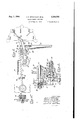
- Figure 1 is a side or end elevation of a machine in accordance with this invention
- Figure 2 is a front elevation of the machine in Figure 1
- FIG. 3 is an enlarged elevation, with parts in cross-section, showing certain details of the operating linkage
- Figure 4 is another detail view
- Figure 5 is a side or end elevation view illustrating the various positions of the manual operating lever.
- the reel 2 which may be of any suitable construction has a hub 3 which is rotatably mounted on a shaft 4 supported within a transverse plate 5 carried by a beam 6 of channel section extending the length of the machine which may comprise'a number of such units in two rows, one in front and the other in back of the channel beam 8.
- I Two gears 1 and 8 are secured to the reel hub 3 for rotation therewith.
- the reel is driven by the gear I which meshes with the gear 8 on a second shaft I supported within suitable bear ings within the plate 5.
- This second shaft III carries a loose pulley I l which is driven by a belt l2 which receives power from the pulley l3 mounted upon the driveshaft i4 which extends the length of the machine.
- the loose pulley H (see Figure is provided with a pin I! which projects from that face of the pulley which is adjacent a collar is which is keyed to the shaft It for axial motion'therealong.
- This collar or slipper member i8 is normally pressed against the face of the pulley by means of a spring I! which backs up against a fixed collar I8 upon the shaft Hi.
- the slidable collar I6 is provided with one or more radially outwardly extending lugs i9 (two being shown) which as shown in Figures 3 and 5, are engaged by the pin ii of the pulley l I when the spring I1 is allowed to press the collar i8 into-contact with the pulley ll.
- the pin l 5 on the loose pulley Ii and one of the lugs l9 upon the collar l6 constitutes a clutch to transmit motion from the loose pulley ll through the collar IE to the shaft l0 and thereby drive the gear 9 which in turn drives the gear 1 ( Figures 1 and 2) andthe reel.
- the slidable collar I8 is provided with an annular groove 20 which is adapted to receive a forked member 2
- serves to disengage the clutch or to permit its reengagement in a manner and by means of connections which will be described hereinafter.
- a traverse arm 25 ( Figures 1 and 2) carrying the traverse guide 28 is fixedly secured to a vertical shaft 21 which is supported for oscillation within the channel beam 8.
- the vertical shaft 21 may be oscillated by suitable connections to the drive mechanism of the reel, such as to gear 8 on the reel hub as shown in Patent 1,824,658.
- I and with the auxiliary guide 84 may be supported upon an angle plate 36 whose foot 36 is secured to the guide supporting beam 30.
- a thread breakage detector in the form of a bell crank lever having two legs 31 and 28 is associated with each of the unwinding filamentary strands.
- the bell crank lever may be pivotally supported upon a substantially horizontal axis extending through the plate 35.
- the legs of the bell crank lever have arms 38 and 40 respectively
- a platform 28 extends the length of the maextending at right angles thereto.
- is secured to a slender rod 42 which extends through it approximately at right angles.
- the slender rod 42 extends through the opposite end walls 43 and 44 of a bracket 45 supported upon the'beam 30. One end extends through a slot 46 in the vertical wall 43 of the bracket 45 and is drawn to one end of the slot by means of a spring 41.
- the other end 48 of the rod 42 is provided with a shoulder which is adapted to bear against the inside of the other vertical wall 44.
- This latter end is of smaller diameter and extends through a small hole of substantially circular outline which is sufliciently large to permit a limited amount of swinging motion of the rod 42 therein.
- rests upon horizontally extending arms 49 of both detectors. To prevent these two arms 40 from interfering with each other, one of them is offset at 49 with respect to the other so that the breaks age of either filamentary strand will be transmitted independently to the bar.
- is designed so that it has a tendency to rest in the position shown in Figure 1 upon the supporting arms 40 of the two detector members.
- Each of the bell-crank lever detectors is so designed that it normally tends to lean against the yarn as shown in Figure 1 and upon breakage of the yarn exerts suflicient clockwise moment to fall in that direction and lift the bar 4
- is provided with a roller 50 which, upon counterclockwise rotation of the bar 4
- also carries an outwardly extending arm 10 on which a manual reset lever II is pivoted.
- This lever is connected by a link 12 pivotally attached thereto at a point 13 offset from the pivotal axis of the lever to another car 14 upon the sleeve 62 carrying the cam bOsses 64 so that the swinging of the lever from an approximately vertical position toward the operator through a short arc serves to start the machine.
- the machine may be provided with the yardage stopping mechanism of Patent 1,952,969 which comprises the helically grooved yardage measuring wheel 15 which rotates a certain number of revolutions for a definite number of yards and which is provided with the radial slot I6 at the outer end of the groove.
- a rod 11 adapted to be longitudinally slidable within a supporting yoke 18 which .permits the rod to move axially of the grooved wheel is normally biased by means traverse arm 25.
- a link 52 has a portion 53 extending vertically down through the top of the bracket 45 and has a notch 54 adapted to catch upon the rod 42 to latch the link 52 in the position shown in Figure 1.
- a spring 55 surrounds the portion 53 of the link and bears against a collar 56 secured to it, tending to force the link upwardly.
- the link 52 may be provided with an offset portion 51 adapted to receive a pad 58 to accommodate the hand for manual depression of the link to latch it.
- the uppermost end of the link 52 (see Figures 1, 2, 3 and 5) is provided with a longitudinal slot 59 into which a pin 60 extends from a projecting ear 6
- a spring 63 is provided and tends to pull the ear 6
- the sleeve 62 is provided with one or more bosses 64 ( Figure 3) adapted to cooperate with corresponding recesses 65, within a stationary sleeve 66 secured within the supporting plate 5 by means of pins 61.
- a helical spring 68 surrounds the pin shaft 23 within a housing therefor providedfby the boss 24 on the plate 5' and presses, against the back face of the stationary sleeve 66 and -against the integral collar 69 of the pin shaft 23,
- the other end of the rod 11 is provided with a plate 18a in which an arcuate slot 19a is provided to receive a pin 30 extending from the car 14 on the cam bossed sleeve 62.
- the rod 11 may be provided with a transverse pin 8
- the breakage link 52 is provided with a slot 59 of sufficient length so that counterclockwise rotation of the cam bossed sleeve 62 as a result of the operation of the yard- --age stop rod 11 moves the pin 60 freely upward from its normal operating position near the middle or preferably adjacent but not too close to the bottom of slot 59 so that the connection between the sleeve 62 and the'breakage link 52 does not interfere with the stopping efiected by yardage rod 11.
- the counterclockwise rotation of the same sleeve 62 by the breakage link 52 is not interfered with because of the free motion of pin 86 in the ,arcuate slot 19a within the plate 18a on the rod Tl.
- the linkage is so arranged that independent operation of either the yardage stop mechanism or the breakage stop mechanism is available without interference from each other.
- the distance between the pivot of the operating lever II and the connection 13 of the operating nectlon 13 has but a slight distance to go from the running position of the operating lever H to a dead center, the amount of this additional displacement being selected tobe equivalent to the amount of additional displacement of the rod "to withdraw it to a point outside the periphery of the grooved wheel 15 so that the action of the spring I9 causes this rod 11 to be reset into the proper starting position in the helical rooveof wheel I5.
- the operator may in resetting the device merely proceed through this dead center into the run" position just beyond it whether above or below it.
- is swung back to either an upwardly or downwardly extending position respectively with an inclination aperator to accidentally withdraw the rod I1 from the groove of the yardage wheel 18 in the midst of a skein since the strong spring I. opposes such action and ordinarily, as stated below.
- the point of the rod ll may drag against the grooved wheel and lodge in one of the outer grooves simply because the operator failed to exert sufllcient pressure upon the operating lever II to prevent such dragging.
- the yardag mechanism comprising rod 11 is reset by swinging the operating lever H through a dead center into the run position beyond the dead center, thus assuring that In operation of the device, should the thread.
- the rod 11 which follows the grooved measuring wheel 1! falls into the radial slot 16 therein as a result of the action ofthe spring 19 and the motion of the rod 'I'I causes a counterclockwise rotation of the sleeve 62, thereby disengaging the clutch and throwing the operating lever H into the stop position.
- a winding machine comprising a winding core on a rotatable shaft, a driving shaft, means comprising a clutch for-connecting the two shafts in driving relationship, a member movable to and from alternate positions for alternately. engaging and disengaging the clutch, a cam member for controlling the movement of the movable member, an element movable in response to a predetermined length of material to be wound. a second element movable in response to breakage of the material being wound, each of the two elements being independently connected to the cam member for transmitting motion to the cam member in one direction only to effect motion of themovable member into the position to disengage the clutch upon the winding of a predetermined length of'material or breakage thereof respectively.
- a winding machine comprising a winding core on a rotatable shaft, a driving shaft, means for controlling the movement of the movable member, an element movable in response to a predetermined length of material to be wound, a second element movable in response to breakage of the material being wound, each of the two elements being independently connected to the cam member for transmitting motion to the cam member in one direction only to effect motion -o1 the movable member into the position to disengage the clutch uponthe winding of a predetermined length of material or breakage thereof respectively, a pivotally mounted manual reset lever, and a link connecting the lever to the cam member for positive transmission of motion in both directions between the cam member and ever.
- a winding machine comprising a winding core on a rotatable shaft, a driving shaft, means comprising a clutch for connecting the two shafts in driving relationship, a member movable to and from alternate positions for alternately engaging and disengaging the clutch, a cam member for controlling the movement of the movable member, an element movable in response to a predetermined length of material to be wound, means for resetting the movable element to its initial position, a second element movable in response to breakage of the material being wound, each of the two elements being independently connected to the cam member for transmitting motion to the cam member in one direction only to effect motion of the movable member into the position to disengage the clutch upon the winding of a predetermined length of material or breakage thereof respectively, said resetting means comprising'a pivotally mounted manual reset lever,
- connection of the first movable element with the cam member being arranged so that motion of the cam memberto a position beyond that corresponding to engagement of the clutch retracts the first movable element into the influence of the resetting means.
- connection between the link and the reset lever being so arranged that it through a dead center as the lever is swung to'retract the movable element to resetting position.
- a winding machine comprising a winding core on a rotatable shaft, 9, driving shaft, means comprising a clutch for connecting the two shafts in driving relationship, a member movable to and motion of at least one of the movable elements effects rotation of the sleeve to cause disengagement of the clutch.
- a winding machine comprising a winding core on a rotatable shaft, a driving shaft, means comprising a clutch for connecting the two shafts in driving relationship, a forked member secured from alternate positions for alternately engaging and disengaging the clutch, a cam member for controlling the movement of the movable member,
- each of the two elements being independently connected to the cam memlink connecting the'lever to the cam member for positive transmission of motion in both directions between the cam member and lever, spring means attached to the first movable element arranged to reset the element to its initial position upon retraction of the element to a position beyond its normal operating position, the first element being arranged to be retracted to resetting position by swinging of the reset lever beyond its position corresponding to engagement of the clutch, the connection between the link and reset lever being so arranged that it passes through a dead center as the movable element is retracted to resetting position.
- a winding machine comprising a winding core on a rotatable shaft, a driving shaft, means comprising a clutch for connecting the two shafts in driving relationship, a forked member secured to an axially slidable pin shaft and movable to and from alternate positions for alternately engaging and disengaging the clutch, a sleeve rotatably mounted on the pin shaft and provided with cam bosses arranged to be received by and withdrawn from corresponding recesses in an adjacent stationary member upon rotation of the sleeve with respect thereto for controlling movement of the forked member, an element movable in response to a predetermined length of material to be wound, a second element movable in response to breakage of the material being wound, thetwo elements being connected tothe sleeve by separate pins secured to the sleeve and extending through a corresponding slot in the elements, the pins and slots being so arranged that the pins are disposed adjacent the corresponding ends of the slots in operating position whereby responsive to an axially s
- a winding machine comprising a winding core on a rotatable shaft, a driving shaft, means comprising a clutch for connecting the two shafts in driving relationship, a member movable to and from alternate positions for alternately engaging and disengaging the clutch, a second movable member for controlling the movement of the first movable member, an element movable in response to a predetermined length of material to be wound, a second element movable in response to breakage of the material being wound, each of the two elements being independently connected to the second movable member for transmitting motion thereto in one-direction only to effect motlon of the first movable member into the position to disengage the clutch upon the winding of a predetermined length of material or breakage thereof respectively.
Landscapes
- Engineering & Computer Science (AREA)
- Quality & Reliability (AREA)
- Winding Of Webs (AREA)
Description
1944- J. H. BRADNACK ET AL 2,354,792
SKEIN WINDING MACHINE Filed May 21, 1943 2 Sheets-Sheet l f/VVENTOPS. JOHN H BAADA/ACK HEW/MN c. E. fez/45x? DONALD C. THOMPSON ATTORNEY.
Aug. 1, I944-' J. H. BRADNACK ETAL SKEIN WINDING MACHINE Filed May 21, 1943 2 Sheets-Sheet 2 IN YEN T0195,
JOHN A! 5010mm HEEMAN c e FOL NEE DONALD C. THOMPSON M 4% Patented Aug. 1, 1944 SKEIN WINDING MACHINE John H. Bradnack and Donald C. Thompson, Roanoke, Va., and Herman C. It. Folmer. Swarthmore, Pa., assignors to American Viscose Corporation, Wilmington, Del., a corporation of Delaware Application May 21, 1943, Serial no. 487,868
This invention relates to skein winding machines and is an improvement over the types of machines disclosed in Crewdson Patent 1,824,658 and in Breakell et al. Patent 1,952,969.
It is an object of this invention to provide skein winding machines with a yarnbreakage detector and stop mechanism which is capable of operating independently of the yardage-stop mechanism. It is a further object to so arrange or interlock the yardage and the breakage stop mechanism that in case the operator fails to take account of the particular cause of stoppage when he subsequently attempts to start the machine his efforts will be unsuccessful. In this manner, it is certain that he will tie in the yarn ii it is broken or that he will doif the machine if a full skein is wound as indicated by operation of the yardage stop mechanism. A further object is to provide an improved reset linkage for the yardage mechanism of the type disclosed in Breakell et al. Patent 1,952,969 so that the operator can be certain of resetting the yardage mechanism to the proper starting position. Other objects and advantages will be apparent from the drawings and the description thereof hereinafter.
In the drawings, illustrative of the-invention,
Figure 1 is a side or end elevation of a machine in accordance with this invention,
Figure 2 is a front elevation of the machine in Figure 1,
Figure 3 is an enlarged elevation, with parts in cross-section, showing certain details of the operating linkage,
Figure 4 is another detail view, and- Figure 5 is a side or end elevation view illustrating the various positions of the manual operating lever.
The reel 2 which may be of any suitable construction has a hub 3 which is rotatably mounted on a shaft 4 supported within a transverse plate 5 carried by a beam 6 of channel section extending the length of the machine which may comprise'a number of such units in two rows, one in front and the other in back of the channel beam 8. I Two gears 1 and 8 are secured to the reel hub 3 for rotation therewith. The reel is driven by the gear I which meshes with the gear 8 on a second shaft I supported within suitable bear ings within the plate 5. This second shaft III carries a loose pulley I l which is driven by a belt l2 which receives power from the pulley l3 mounted upon the driveshaft i4 which extends the length of the machine. The loose pulley H (see Figure is provided with a pin I! which projects from that face of the pulley which is adjacent a collar is which is keyed to the shaft It for axial motion'therealong. This collar or slipper member i8 is normally pressed against the face of the pulley by means of a spring I! which backs up against a fixed collar I8 upon the shaft Hi. The slidable collar I6 is provided with one or more radially outwardly extending lugs i9 (two being shown) which as shown in Figures 3 and 5, are engaged by the pin ii of the pulley l I when the spring I1 is allowed to press the collar i8 into-contact with the pulley ll. Thus, in the position shown in Figure 3, the pin l 5 on the loose pulley Ii and one of the lugs l9 upon the collar l6 constitutes a clutch to transmit motion from the loose pulley ll through the collar IE to the shaft l0 and thereby drive the gear 9 which in turn drives the gear 1 (Figures 1 and 2) andthe reel. The slidable collar I8 is provided with an annular groove 20 which is adapted to receive a forked member 2| which extends from a sleeve 22 secured to a pin shaft 23 which is axially slidable within a bearing formed in a boss 24 which forms a part of the supporting plate 5. The forked member 2| serves to disengage the clutch or to permit its reengagement in a manner and by means of connections which will be described hereinafter.
A traverse arm 25 (Figures 1 and 2) carrying the traverse guide 28 is fixedly secured to a vertical shaft 21 which is supported for oscillation within the channel beam 8. The vertical shaft 21 may be oscillated by suitable connections to the drive mechanism of the reel, such as to gear 8 on the reel hub as shown in Patent 1,824,658.
I and with the auxiliary guide 84 may be supported upon an angle plate 36 whose foot 36 is secured to the guide supporting beam 30.
A thread breakage detector in the form of a bell crank lever having two legs 31 and 28 is associated with each of the unwinding filamentary strands. The bell crank lever may be pivotally supported upon a substantially horizontal axis extending through the plate 35. The legs of the bell crank lever have arms 38 and 40 respectively A platform 28 extends the length of the maextending at right angles thereto. A bar 4| is secured to a slender rod 42 which extends through it approximately at right angles. The slender rod 42 extends through the opposite end walls 43 and 44 of a bracket 45 supported upon the'beam 30. One end extends through a slot 46 in the vertical wall 43 of the bracket 45 and is drawn to one end of the slot by means of a spring 41. The other end 48 of the rod 42 is provided with a shoulder which is adapted to bear against the inside of the other vertical wall 44. This latter end is of smaller diameter and extends through a small hole of substantially circular outline which is sufliciently large to permit a limited amount of swinging motion of the rod 42 therein. Where two skeinsare wound upon a single reel as shown, the bar 4| rests upon horizontally extending arms 49 of both detectors. To prevent these two arms 40 from interfering with each other, one of them is offset at 49 with respect to the other so that the breaks age of either filamentary strand will be transmitted independently to the bar. The bar 4| is designed so that it has a tendency to rest in the position shown in Figure 1 upon the supporting arms 40 of the two detector members. Each of the bell-crank lever detectors is so designed that it normally tends to lean against the yarn as shown in Figure 1 and upon breakage of the yarn exerts suflicient clockwise moment to fall in that direction and lift the bar 4| so that it in turn swings in a counterclockwise direction about its rod 42 as an axis. The rear end of the bar 4| is provided with a roller 50 which, upon counterclockwise rotation of the bar 4|, falls in the way of the foot of 9. dependin arm 5| attached to the' with a mechanism for stopping the machine when a predetermined number of yards has been wound.
The sleeve 22 carrying the forked member 2| also carries an outwardly extending arm 10 on which a manual reset lever II is pivoted. This lever is connected by a link 12 pivotally attached thereto at a point 13 offset from the pivotal axis of the lever to another car 14 upon the sleeve 62 carrying the cam bOsses 64 so that the swinging of the lever from an approximately vertical position toward the operator through a short arc serves to start the machine.
The machine may be provided with the yardage stopping mechanism of Patent 1,952,969 which comprises the helically grooved yardage measuring wheel 15 which rotates a certain number of revolutions for a definite number of yards and which is provided with the radial slot I6 at the outer end of the groove. A rod 11 adapted to be longitudinally slidable within a supporting yoke 18 which .permits the rod to move axially of the grooved wheel is normally biased by means traverse arm 25. A link 52 has a portion 53 extending vertically down through the top of the bracket 45 and has a notch 54 adapted to catch upon the rod 42 to latch the link 52 in the position shown in Figure 1. A spring 55 surrounds the portion 53 of the link and bears against a collar 56 secured to it, tending to force the link upwardly. The link 52 may be provided with an offset portion 51 adapted to receive a pad 58 to accommodate the hand for manual depression of the link to latch it. The uppermost end of the link 52 (see Figures 1, 2, 3 and 5) is provided with a longitudinal slot 59 into which a pin 60 extends from a projecting ear 6| secured to a sleeve 62 which is rotatably mounted upon the pin shaft 23 carrying the fork lever 2| A spring 63 is provided and tends to pull the ear 6| downwardly with respect to the link 52 to which the spring is anchored, but spring 63 is of less strength than spring 19 for reasons explained hereinafter.
The sleeve 62 is provided with one or more bosses 64 (Figure 3) adapted to cooperate with corresponding recesses 65, within a stationary sleeve 66 secured within the supporting plate 5 by means of pins 61. A helical spring 68 surrounds the pin shaft 23 within a housing therefor providedfby the boss 24 on the plate 5' and presses, against the back face of the stationary sleeve 66 and -against the integral collar 69 of the pin shaft 23,
urging the pin shaft 23 with the forked lever 2| into the position shown in Figure 3. It will be readily appreciated that upon rotation of the sleeve 62 about the pin shaft 23 the forked lever 2| is urged outwardly against the action of the spring 68 as. a result of the cam bosses 64 riding out of their recesses 65 onto the face of the stationary sleeve, 66. This means for disconnection of the loose pulley II from the slidable collar IS on the shaft I0 is shown in Patent 1,824,658 where, however, it is shown only in combination of a spring 19 so that its end is forced into the groove on the wheel 15. The other end of the rod 11 is provided with a plate 18a in which an arcuate slot 19a is provided to receive a pin 30 extending from the car 14 on the cam bossed sleeve 62. The rod 11 may be provided with a transverse pin 8| to limit longitudinal motion of the rod upon falling into the radial slot 16 within the grooved wheel 15.
It will be noted that the breakage link 52 is provided with a slot 59 of sufficient length so that counterclockwise rotation of the cam bossed sleeve 62 as a result of the operation of the yard- --age stop rod 11 moves the pin 60 freely upward from its normal operating position near the middle or preferably adjacent but not too close to the bottom of slot 59 so that the connection between the sleeve 62 and the'breakage link 52 does not interfere with the stopping efiected by yardage rod 11. Similarly, the counterclockwise rotation of the same sleeve 62 by the breakage link 52 is not interfered with because of the free motion of pin 86 in the ,arcuate slot 19a within the plate 18a on the rod Tl. Thus, the linkage is so arranged that independent operation of either the yardage stop mechanism or the breakage stop mechanism is available without interference from each other.
Preferably, as shown particularly in Figure 5, the distance between the pivot of the operating lever II and the connection 13 of the operating nectlon 13 has but a slight distance to go from the running position of the operating lever H to a dead center, the amount of this additional displacement being selected tobe equivalent to the amount of additional displacement of the rod "to withdraw it to a point outside the periphery of the grooved wheel 15 so that the action of the spring I9 causes this rod 11 to be reset into the proper starting position in the helical rooveof wheel I5. By making the reset position correspond'to a dead center for the link connection 13 with respect to the main pivot of the operating lever II and the pin connection of the link 12 with the sleeve 62, the operator may in resetting the device merely proceed through this dead center into the run" position just beyond it whether above or below it. When the machine is running with the lever in either the upper or lowerjrurl position, the lever 1| is swung back to either an upwardly or downwardly extending position respectively with an inclination aperator to accidentally withdraw the rod I1 from the groove of the yardage wheel 18 in the midst of a skein since the strong spring I. opposes such action and ordinarily, as stated below. it is sufficient to press on pad 58 to start the machine except when the yardage mechanism needs to be reset. In Patent,l,952,-969, there may be a tendency on the part of the operator, when he intends to reset the rod ll, to fail to exert suilicient force against the spring I! to bring the rod 'll clear back to the proper starting groove. For
example, the point of the rod ll may drag against the grooved wheel and lodge in one of the outer grooves simply because the operator failed to exert sufllcient pressure upon the operating lever II to prevent such dragging. In the present application, the yardag mechanism comprising rod 11 is reset by swinging the operating lever H through a dead center into the run position beyond the dead center, thus assuring that In operation of the device, should the thread.
break in the midst of a skein, the detector arm .39 falls and causes the counterclockwise rotation,
uf the bar ll into the path of the arm 5| fastened to the traverse arm 25. When 'arm 5| strikes the bar 4|, the latter swings its rod 42 through the slot 46 against the action of the spring 41, freeing the rod 42 from the notch 54 within the vertical link II which is immediately forced upwardly by the .helical spring 55. The upward momentum of link 52 transmits counterclockwise motion to the cam bossed sleeve 62 through the pin 60 in its ear 6| which is nor mally positioned near the middle or lower' end of the slot 59 during running of the machine. The rotation of the sleeve 62 moves the operating lever H into the stop position ;-and causes the forked lever 2| to move the slidable collar I 6 'to disengage its lug is from the pin ii on the loose pulley ll.
In order to start the machine after the yarn has broken, the yarn is tied in and the vertical link 52 is depressed by application of the heel of the hand against the pad 58 until operating lever II is thrown into, running position by the action of pin 60 and ear 6| on the sleeve 62. This causes rod 42 carried by the bar ll to be latched within the notch 54 of the link.
Upon completion of a skein, the rod 11 which follows the grooved measuring wheel 1! falls into the radial slot 16 therein as a result of the action ofthe spring 19 and the motion of the rod 'I'I causes a counterclockwise rotation of the sleeve 62, thereby disengaging the clutch and throwing the operating lever H into the stop position.
To start the machineafter the completion of a full skein, the operator dofls the reel and then merely turns the lever 1| through its dead center position to reset the rod 11 in the-proper groove of the yardage wheel 15. Should the operator forget to reset the yardage mechanism, it would be impossible to start'the reel by pressing down' on pad 58, because spring 63 is not strong enough to overcome the tension of spring 19.
Should the skein be completed simultaneously with the breakage of a thread, it will be apparent from the description of the connections hereinabove that the operator will be unable to start the machine without being notified of the fact that a full skein has been wound. V
.There is thus provided by this invention operator of what the cause of stoppage is and which must be independently reset before operation of the machine can be resumed.
While preferred embodiments of the invention have been disclosed, it is to be understood that changes and variations may be made without departing from the spirit and scope of the invention as defined by the appended claims.
We claim: 1.-A winding machine comprising a winding core on a rotatable shaft, a driving shaft, means comprising a clutch for-connecting the two shafts in driving relationship, a member movable to and from alternate positions for alternately. engaging and disengaging the clutch, a cam member for controlling the movement of the movable member, an element movable in response to a predetermined length of material to be wound. a second element movable in response to breakage of the material being wound, each of the two elements being independently connected to the cam member for transmitting motion to the cam member in one direction only to effect motion of themovable member into the position to disengage the clutch upon the winding of a predetermined length of'material or breakage thereof respectively.
2. A winding machine comprisinga winding core on a rotatable shaft, a driving shaft, means for controlling the movement of the movable member, an element movable in response to a predetermined length of material to be wound, a second element movable in response to breakage of the material being wound, each of the two elements being independently connected to the cam member for transmitting motion to the cam member in one direction only to effect motion -o1 the movable member into the position to disengage the clutch uponthe winding of a predetermined length of material or breakage thereof respectively, a pivotally mounted manual reset lever, and a link connecting the lever to the cam member for positive transmission of motion in both directions between the cam member and ever.
3. A winding machine comprising a winding core on a rotatable shaft, a driving shaft, means comprising a clutch for connecting the two shafts in driving relationship, a member movable to and from alternate positions for alternately engaging and disengaging the clutch, a cam member for controlling the movement of the movable member, an element movable in response to a predetermined length of material to be wound, means for resetting the movable element to its initial position, a second element movable in response to breakage of the material being wound, each of the two elements being independently connected to the cam member for transmitting motion to the cam member in one direction only to effect motion of the movable member into the position to disengage the clutch upon the winding of a predetermined length of material or breakage thereof respectively, said resetting means comprising'a pivotally mounted manual reset lever,
a link connecting the lever to the cam member for positive transmission of moticnln both directions between the cam member and lever, the connection of the first movable element with the cam member being arranged so that motion of the cam memberto a position beyond that corresponding to engagement of the clutch retracts the first movable element into the influence of the resetting means. the connection between the link and the reset lever being so arranged that it through a dead center as the lever is swung to'retract the movable element to resetting position.
4. A winding machine comprising a winding core on a rotatable shaft, 9, driving shaft, means comprising a clutch for connecting the two shafts in driving relationship, a member movable to and motion of at least one of the movable elements effects rotation of the sleeve to cause disengagement of the clutch.
6. A winding machine comprising a winding core on a rotatable shaft, a driving shaft, means comprising a clutch for connecting the two shafts in driving relationship, a forked member secured from alternate positions for alternately engaging and disengaging the clutch, a cam member for controlling the movement of the movable member,
an element movable in response to a predetermined length of material to be wound, a second element movable in response to breakage of the material being wound, each of the two elements being independently connected to the cam memlink connecting the'lever to the cam member for positive transmission of motion in both directions between the cam member and lever, spring means attached to the first movable element arranged to reset the element to its initial position upon retraction of the element to a position beyond its normal operating position, the first element being arranged to be retracted to resetting position by swinging of the reset lever beyond its position corresponding to engagement of the clutch, the connection between the link and reset lever being so arranged that it passes through a dead center as the movable element is retracted to resetting position.
5. A winding machine comprising a winding core on a rotatable shaft, a driving shaft, means comprising a clutch for connecting the two shafts in driving relationship, a forked member secured to an axially slidable pin shaft and movable to and from alternate positions for alternately engaging and disengaging the clutch, a sleeve rotatably mounted on the pin shaft and provided with cam bosses arranged to be received by and withdrawn from corresponding recesses in an adjacent stationary member upon rotation of the sleeve with respect thereto for controlling movement of the forked member, an element movable in response to a predetermined length of material to be wound, a second element movable in response to breakage of the material being wound, thetwo elements being connected tothe sleeve by separate pins secured to the sleeve and extending through a corresponding slot in the elements, the pins and slots being so arranged that the pins are disposed adjacent the corresponding ends of the slots in operating position whereby responsive to an axially slidable pin shaft, and movable to and from alternate positions for alternately engaging and disengaging the clutch, a sleeve rotatably mounted on the pin shaft and provided with cam bosses arranged to be received by and withdrawn from corresponding recesses in an ad- Jacent stationary member upon rotation of the sleeve with respect thereto for controlling movement of the forked member, an element having a slot and being movable inresponse to a predetermined length of material to be wound, a second element having a slot and being movable in response to breakage of the material being wound, the two elements being connected to the sleeve by separate pins secured to the sleeve extending throughtheir respective slots, the pins and slots being so arranged that the pins are disposed adjacent the corresponding ends of the slots in operating position whereby responsive motion of at least one of the movable elements effects rotation of the sleeve to causedisengagement of the clutch, a manual reset lever pivotally mounted on an arm supported on the forked member, a link having one end pivotally connected to this lever and its other end pivoted on the pin connecting the sleeve to the first movable element, means for resetting the first movable element to its initial position upon retraction to a position beyond its normal operating position by swinging of the manual lever beyond its position corresponding to engagement of the clutch, the distance between the lever pivot and the pivotal connection of the link to the lever being such that swinging of the lever beyond normal operating position causes the latter connection to pass through a dead centar as it retracts the first movable element into a position under the influence of the resetting means.
'7. A winding machine comprising a winding core on a rotatable shaft, a driving shaft, means comprising a clutch for connecting the two shafts in driving relationship, a member movable to and from alternate positions for alternately engaging and disengaging the clutch, a second movable member for controlling the movement of the first movable member, an element movable in response to a predetermined length of material to be wound, a second element movable in response to breakage of the material being wound, each of the two elements being independently connected to the second movable member for transmitting motion thereto in one-direction only to effect motlon of the first movable member into the position to disengage the clutch upon the winding of a predetermined length of material or breakage thereof respectively.
, JOHN H, BRADNACK.
DONALD C. THOMPSON. HERMAN C. R. FOLMER.
Priority Applications (1)
| Application Number | Priority Date | Filing Date | Title |
|---|---|---|---|
| US487868A US2354792A (en) | 1943-05-21 | 1943-05-21 | Skein winding machine |
Applications Claiming Priority (1)
| Application Number | Priority Date | Filing Date | Title |
|---|---|---|---|
| US487868A US2354792A (en) | 1943-05-21 | 1943-05-21 | Skein winding machine |
Publications (1)
| Publication Number | Publication Date |
|---|---|
| US2354792A true US2354792A (en) | 1944-08-01 |
Family
ID=23937445
Family Applications (1)
| Application Number | Title | Priority Date | Filing Date |
|---|---|---|---|
| US487868A Expired - Lifetime US2354792A (en) | 1943-05-21 | 1943-05-21 | Skein winding machine |
Country Status (1)
| Country | Link |
|---|---|
| US (1) | US2354792A (en) |
Cited By (3)
| Publication number | Priority date | Publication date | Assignee | Title |
|---|---|---|---|---|
| US2714491A (en) * | 1953-09-04 | 1955-08-02 | Universal Winding Co | Interlocking control means for the stop-motions of multi-spindle machines |
| US3334830A (en) * | 1965-04-08 | 1967-08-08 | Antoni Carlo Degli | Positioning device for the thread guide of a reeling machine |
| US4226378A (en) * | 1976-02-13 | 1980-10-07 | Baxter Travenol Laboratories, Inc. | Method and apparatus for winding hollow filaments |
-
1943
- 1943-05-21 US US487868A patent/US2354792A/en not_active Expired - Lifetime
Cited By (3)
| Publication number | Priority date | Publication date | Assignee | Title |
|---|---|---|---|---|
| US2714491A (en) * | 1953-09-04 | 1955-08-02 | Universal Winding Co | Interlocking control means for the stop-motions of multi-spindle machines |
| US3334830A (en) * | 1965-04-08 | 1967-08-08 | Antoni Carlo Degli | Positioning device for the thread guide of a reeling machine |
| US4226378A (en) * | 1976-02-13 | 1980-10-07 | Baxter Travenol Laboratories, Inc. | Method and apparatus for winding hollow filaments |
Similar Documents
| Publication | Publication Date | Title |
|---|---|---|
| US2238230A (en) | Apparatus for producing cops | |
| US2338914A (en) | Cross winding frame | |
| US2354792A (en) | Skein winding machine | |
| US2599256A (en) | Yarn twisting machine | |
| US2335975A (en) | Control device | |
| US2575476A (en) | Twisting and winding machine drive system | |
| US2029943A (en) | Yarn and thread tensioning mechanism for cop winding and like textile machines | |
| US3565356A (en) | Friction roller for driving winding-up bobbins at the circumference thereof | |
| US3291406A (en) | Control device for a winding machine | |
| US2316462A (en) | Winding machine having a plurality of winding spindles | |
| US2079570A (en) | Braiding carrier | |
| US1600894A (en) | Spinning frame | |
| US3062462A (en) | Device for driving winding bobbins in automatic cross winders | |
| US1882500A (en) | Winding machine | |
| US459040A (en) | Yarn-spooling machine | |
| US2930182A (en) | Automatic stopping device for stopping thread twisting machines | |
| US1526918A (en) | Tension means | |
| US2492713A (en) | Guide for paper rolling machines | |
| US514884A (en) | Spooling-machine | |
| US2084770A (en) | Knitted strand covering machine | |
| US2450074A (en) | Bobbin lifter | |
| US3292358A (en) | Stop motion for winding and twisting machine | |
| US2260921A (en) | Winding machine | |
| US1590028A (en) | Machine for winding yarns or threads | |
| US1430254A (en) | Winder |