US2353125A - Apparatus for cleaning pipe - Google Patents
Apparatus for cleaning pipe Download PDFInfo
- Publication number
- US2353125A US2353125A US411534A US41153441A US2353125A US 2353125 A US2353125 A US 2353125A US 411534 A US411534 A US 411534A US 41153441 A US41153441 A US 41153441A US 2353125 A US2353125 A US 2353125A
- Authority
- US
- United States
- Prior art keywords
- pipe
- brush
- support
- axis
- cleaning
- Prior art date
- Legal status (The legal status is an assumption and is not a legal conclusion. Google has not performed a legal analysis and makes no representation as to the accuracy of the status listed.)
- Expired - Lifetime
Links
Images


Classifications
-
- B—PERFORMING OPERATIONS; TRANSPORTING
- B08—CLEANING
- B08B—CLEANING IN GENERAL; PREVENTION OF FOULING IN GENERAL
- B08B9/00—Cleaning hollow articles by methods or apparatus specially adapted thereto
- B08B9/02—Cleaning pipes or tubes or systems of pipes or tubes
- B08B9/023—Cleaning the external surface
-
- Y—GENERAL TAGGING OF NEW TECHNOLOGICAL DEVELOPMENTS; GENERAL TAGGING OF CROSS-SECTIONAL TECHNOLOGIES SPANNING OVER SEVERAL SECTIONS OF THE IPC; TECHNICAL SUBJECTS COVERED BY FORMER USPC CROSS-REFERENCE ART COLLECTIONS [XRACs] AND DIGESTS
- Y10—TECHNICAL SUBJECTS COVERED BY FORMER USPC
- Y10S—TECHNICAL SUBJECTS COVERED BY FORMER USPC CROSS-REFERENCE ART COLLECTIONS [XRACs] AND DIGESTS
- Y10S29/00—Metal working
- Y10S29/098—Rotating, reciprocating or oscillating cleaner
-
- Y—GENERAL TAGGING OF NEW TECHNOLOGICAL DEVELOPMENTS; GENERAL TAGGING OF CROSS-SECTIONAL TECHNOLOGIES SPANNING OVER SEVERAL SECTIONS OF THE IPC; TECHNICAL SUBJECTS COVERED BY FORMER USPC CROSS-REFERENCE ART COLLECTIONS [XRACs] AND DIGESTS
- Y10—TECHNICAL SUBJECTS COVERED BY FORMER USPC
- Y10T—TECHNICAL SUBJECTS COVERED BY FORMER US CLASSIFICATION
- Y10T29/00—Metal working
- Y10T29/45—Scale remover or preventor
- Y10T29/4506—Scale remover or preventor for hollow workpiece
Definitions
- the invention has as its primary object the substantial simplification of the design and construction of I devices heretofore employed for accomplishing the stated function on a commercial scale whereby the apparatus employed may be more economically constructed and operated and more readily maintained in operative condition.
- This principal object is accomplished by the present invention without sacrificing the productive speed heretofore attained and, in fact, the utilization of devices constructed according to the present invention enables such productive speeds to be increased.
- thepipe may be transferred to a trimming and/or a threading machine or transferred directly to a cleaning machine, preparatory to the coating and/or wrapping of the same.
- a further object of the presentinvention is to greatly simplify the apparatus employed for these various operations and to simplify the plant procedure fol lowed in the operation of these machines.
- pipe conveyors generally aremore desirably constructed with' skewed supporting rolls which rotate the pipe while advancing the pipe longitudinaly, it is possible to combine the pipe cleaning apparatus of the invention with such straightening machine or other conveyor and thereby greatly simplify the design and operation of the apparatus required to effect the cleaning phase of the pipe preparation.
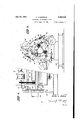
- Figure 1 is a side view, partly broken away, of a pipe cleaning apparatus constructed in accordance with the principles of the invention and showing the same as being positioned adjacent the stock leaving end of a pipe straightening
- Figure'2 is an end view of the apparatus of Figure l;
- FIG. 3 is a transverse section through a modified form of pipe cleaning apparatus constructed in accordance with the invention.
- Figure 4 is a partial side View of the apparatus of Figure 3.
- Figure 5 is a detailed view of a portion ofthe apparatus of' Figures 3 and 4, the View showing the preferred arrangement for conducting electric current to the brush driving motors on the revolving carriage.
- reference numeral Ill indicates a baseor support on which is pivotally mounted at II a platform l2 .built up of metal sections, two spaced parallel pieces of which 'extendoutwardly to one side of the pivot ll. Journal blocks l3 are secured to the outer ends of these pieces and a shaft I4 carrying a stiff wire brush I5 is journaled in the blocks it. Shaft i4 is arranged to be driven by an electric motor l6 which is mounted on the platform 2 .on the side of the pivot H opposite volving brush l5 into engagement with the pipe,
- the motor driven cleaning brush unit described above is capable of wide application and may be used in any situation where means is provided to support the pipe and to simultaneously impart rotational and longitudinal movement to the pipe. As explained above, these conditions are inherent in many pipe conveying devices now employed and the desired cleaning may be effected by properly positioning the said unit in relation to the path of travel of the pipe along the conveyor.
- the base [0 and the platform [2 may be made adjustable, or these parts may be specially constructed for each particular installation.
- Figures 1 and 2 illustrate a representative use of the apparatus and in these figures, reference numerals 30 and 3
- the carriage consisting principally of end rings 44 and circumferentially spaced interconnecting struts 45, is revolvably mounted on the tracks 43, being supported by the flanged wheels 46.
- a motor driven brush unit substantially identical in principle and operation to the unit of Figures 1 and 2, is pivotally mounted on each of the shafts 48 and consists of two spaced inwardly directed arms 49 which rotatably support a wire brush 5!] at their inner ends.
- the rings 62 are arranged tore ceive current from brushes 64 which are supminals 66 ⁇ and holders 65" are carried on an insulatingplate '61 which in turnis securedj te' a bracket raster-led tda-sta-tionaryipai t r the machine as, for xamplathe 'supportl l as shown.
- "Each of-the motor rive n' 'brushing units of the apparatus of Figure'Q 3' and 4'- is'providedwith means 156- ad-just-theinner position of the brush and to apply yielding pressure between the brush and the pipe which is substantially identical with the corresponding means I8-23 of the apparatus of Figures 1 and 2.
- said brush resiliently urge said support to rotation in one directionwhereby said brush will maintain yield ingcontact with said surface, said brush adapted to-rctate about an axis substantially parallel with the principal axis of said pipe and having a length at least equal to the pitch of the spiral path imparted to said pipe by said machine.
- An apparatus for cleaning the exterior surface of pipe comprising in combination a base, a support pivotally mounted on said base and carrying a revolvable brush on one sideof the pivotal axis, an electric motor mounted on said support on the opposite side of said pivotal axis thereby'providing a counterweight for said brush, a conically-shaped guard at one end of said brush, and a driving connection between said motor and brush whereby the latter is motor driven.
- An apparatus for cleaning the exterior surface of pipe comprising in combination a carriage adapted to rotate about the principal axis of the pipe and through which the pipe is adapted to be moved longitudinally, a support mounted on said carriage for pivotal movement about an axis extending generally parallel with the axis of rotation of said carriage, a brush revolvably mounted on said support on one side of said pivotal axis and an electric motor mounted on said support on the opposite side of said pivotal axis, means to urge said support to rotate in one direction about said pivotal axis whereby said brush will be maintained in yielding engagement with said surface, and a driving connection between said motor and brush.
- An apparatus for cleaning the exterior surface of pipe comprising in combination a carriage mounted for rotation about the longitudinal axis of said pipe and through which said pipe is adapted to be moved longitudinally, a support carried by said carriage and mounting a motor and a brush, said brush adapted to engage said surface and to be rotated by said motor about an axis substantially parallel with the axis of rotation of said carriage, and a movable connection between said carriage and support whereby said brush may be, maintained in yielding engagement with said surface.
- Apparatus according to claim 5 further including means to conduct electric current to said motor during rotation of said carriage, said means comprising a current conducting ring secured to and rotatable with said carriage, a base rotatably supporting said carriage, and a normally fixed current conducting brush mounted on said base and having pressure contact with said ring.
- An apparatus for cleaning the exterior surfaces of elongated objects in succession as the objects advance longitudinally in a common path comprising a revolvable brush mounted for rotation about an axis substantially parallel with the direction of said path, means to rotate said brush, a conically-shaped guard at one end of said brush, and means to urge said brush into engagement with said objects.
- a supporting member a support pivotally mounted intermediate its end on said member for pivotal movement about an axis generally parallel with the longitudinal axis of the pipe to be cleaned, a revolvable brush carried by one end of said support and adapted to be maintained in contact with saidpipe, a motor mounted on the other end of said support and having driving connection With said brush; and means to rotate said support about its pivot and to vary-the pressure exerted by said brush on said pipe comprising a lug secured to said support, a second lug secured to said supporting'member, a headed bolt slideably received in said first mentioned lug and screw-threadedly received in said second lug, a threaded nut on said bolt intermediate said lugs, and a-coil spring encircling said bolt intermediate said first mentioned lug and said nut, the arrangement being such that by rotation of said bolt the distance 6 between said lugs may be varied without changing the degree of compression of said spring.
Description
y 1944q A. B. VCARPMAIL 2,353,125
' 'APPARATUS FOR CLEANING PIPE Fiied Sept. 19, 1941 s SheetsSheet 1 3mm ARTBHUR cARPMAIL July 11, 1944.
A. B. CARPMAIL APPARATUS FOR CLEANING P IPE 3 Sheets-Sheet 2 Filed Sept. 19, 1941 31 vumwwrl 7 I ARTHUR B. CARPMAIL July 11, 1944. AB. cA m'An, 2,353,125
' APPARATUS FOR CLEANING PIPE Filed Sept 19, 1941 3 sneet-snee't 5 gwwe/vvbo'b ARTHUR B. CARPMAIL Patented July 11, 1944 UNITED STATES PATENT OFFICE APPARATUS FOR CLEANING ms I I Arthur. B. rai plnaii, Lorain, Ohio 7 Application September 19, 1941, Serial No.,,41'1,5,34 t f (01.15 88) This invention relates to apparatus for remov- I 8 Claims ing scale corrosion and other foreign matter from the exterior surface of pipe preparatory to coating and/or wrapping of the same. The invention has as its primary object the substantial simplification of the design and construction of I devices heretofore employed for accomplishing the stated function on a commercial scale whereby the apparatus employed may be more economically constructed and operated and more readily maintained in operative condition. This principal object is accomplished by the present invention without sacrificing the productive speed heretofore attained and, in fact, the utilization of devices constructed according to the present invention enables such productive speeds to be increased.
The above general and specific objects are accomplished in accordance with the invention by employing one or more motor driven brushing units which are pivotally mounted about an axis or axes extending generally parallel with the principal axis of the pipe being cleaned. In addition, means is provided to urge said unit or units to rotation in certain directions whereby the brushes thereof will be held in yieldingly engagement with the outer surface of the pipe and, also, some provision is made whereby relative longitudinal and rotative movement between a pipe and the brushing unit or units is effected. This method of operation may be accomplished in different ways and for-the purpose of illuslt ration, two specific methods are specifically disclosed herein. v i In the manufacture of pipe, whether by manual or by the more modern continuous methods, it is common practice tofirst form the pipe, cut the 'sameto the approximate lengths desired and then transfer the lengths onto cooling tables wherethe stock is allowed tocool'down to submachine;
stantially near atmospherictemperatures. 'I he coolin process results in the formation of scale onthe outer surface of the pipe and somedistortion in the shape of the pipe due to the intrnal stresses set up inthe metal. When the pipeis cool, it ispassed through a straightening machine which consists of a plurality of longitudinally aligned but adjustable passes, each consisting of a pair of upper and 'lowerskewed rolls which are concaved to provide a pass therethrough circular in cross section. The skewed rolls impart both rotation and longitudinal progression to the pipe, as is well understood in the art. From the straightening machine, thepipe may be transferred to a trimming and/or a threading machine or transferred directly to a cleaning machine, preparatory to the coating and/or wrapping of the same. A further object of the presentinvention is to greatly simplify the apparatus employed for these various operations and to simplify the plant procedure fol lowed in the operation of these machines. Inasmuch as the pipe entering or leaving the straightening machine rotates as it advances longitudinally and since pipe conveyors generally aremore desirably constructed with' skewed supporting rolls which rotate the pipe while advancing the pipe longitudinaly, it is possible to combine the pipe cleaning apparatus of the invention with such straightening machine or other conveyor and thereby greatly simplify the design and operation of the apparatus required to effect the cleaning phase of the pipe preparation.
The above and other objects and advantages of the invention will become apparent from a consideration of the following detailed specification and the accompanying drawings wherein there is specifically disclosed certain representative embodiments of the principles of the invention. l r
In the drawings:
Figure 1 is a side view, partly broken away, of a pipe cleaning apparatus constructed in accordance with the principles of the invention and showing the same as being positioned adjacent the stock leaving end of a pipe straightening Figure'2 is an end view of the apparatus of Figure l;
Figure 3 is a transverse section through a modified form of pipe cleaning apparatus constructed in accordance with the invention;
Figure 4 is a partial side View of the apparatus of Figure 3; and
Figure 5 is a detailed view of a portion ofthe apparatus of'Figures 3 and 4, the View showing the preferred arrangement for conducting electric current to the brush driving motors on the revolving carriage.
Referring now to Figures 1 and 2, reference numeral Illindicates a baseor support on which is pivotally mounted at II a platform l2 .built up of metal sections, two spaced parallel pieces of which 'extendoutwardly to one side of the pivot ll. Journal blocks l3 are secured to the outer ends of these pieces and a shaft I4 carrying a stiff wire brush I5 is journaled in the blocks it. Shaft i4 is arranged to be driven by an electric motor l6 which is mounted on the platform 2 .on the side of the pivot H opposite volving brush l5 into engagement with the pipe,
a coil spring I8 is employed, which spring is carried on a threaded rod I9. Rod l9 passes loosely through a member 20 pivotally mounted between the lugs 2| secured to the platform l2 and has its outer end screw-threadedly received in a member 22 pivoted between the lugs 23 attached that all the outer surface will be cleaned. It should be observed that the brush I5 is of substantial length which is greater than the pitch of the spiral path imparted to the pipe by the conveyors and machines mentioned herein. This eliminates the possibility of leaving any spiral portion of the pipe uncleaned.
In the event that it is desired to employ the motor driven cleaning brush unit of the invention Y independently of any conveyor or other apparatus which does not rotate the pipe, an arrangement as disclosed in Figures 3 and 4 may be I utilized. This apparatus consists of a base 40 to the base It). A nut 23 is screw-threaded on,
rod I9 intermediate members and 22 and the spring I8 is held under compression between the member 20 and the nut 23. By rotating rod l9, the platform I 2 is caused to rotate about the pivot H to move the brush l5 toward and away from the longitudinal axis of the pipe without changing the degree of compression or adjustment of the spring Hi. This provides a readily manipulatable arrangement for setting up the machine to clean pipe of different diameters. The extreme outer ends of the shaft l4 are each provided with comically-shaped guards 24' to prevent the end of the pipe from damaging the bearings l5 or the pulley on shaft I4 in the event that these parts are left in the path of travel of the pipe.
The motor driven cleaning brush unit described above is capable of wide application and may be used in any situation where means is provided to support the pipe and to simultaneously impart rotational and longitudinal movement to the pipe. As explained above, these conditions are inherent in many pipe conveying devices now employed and the desired cleaning may be effected by properly positioning the said unit in relation to the path of travel of the pipe along the conveyor. For this purpose the base [0 and the platform [2 may be made adjustable, or these parts may be specially constructed for each particular installation. Figures 1 and 2 illustrate a representative use of the apparatus and in these figures, reference numerals 30 and 3| represent the upper and lower straightening rolls in the last stand of a'conventional pipe straightening machine. As shown, these rolls are concaved and oppositely skewed and it should be apparent that as the rolls. rotate, the pipe 32 fastened therebetween will be caused to rotate as it moves longitudinally. The lower roll 3| is arranged to be driven by a shaft 33 from suitable driving means, not shown, and in practice, three or more similar sets of roll arranged in longitudinal alignment are employed to straighten the pipe as it passes through the machine. Inasmuchas the construction of the straightening machine per se forms no part of the invention, the same is not shown in detail.
In operation, as the pipe 32 issues from the straightening machine or passes along in a conveyor as explained above, its outer surface is engaged by the rapidly revolving wire brush l5 which, being driven at high speeds, is operative to remove all scale corrosion and other foreign matter from the surface of the pipe. Since the pipe rotates about its principal axis, all portions of the outer surface of the same will be subjected to the action of the revolving brush thereby insuring 'having two upwardly extending spaced supports 4|,each provided with a central aperture 42 and *a circular track 43 extending about the periphery of the'ape'rture 42. The carriage, consisting principally of end rings 44 and circumferentially spaced interconnecting struts 45, is revolvably mounted on the tracks 43, being supported by the flanged wheels 46. Securedto each of the struts 45, whichare preferably-channel shaped and three in number as indicated in Figure 3; is a pair of pillow blocks 4'! in which is journaled a shaft 48 extending generally parallel with the axis of rotation of the carriage. A motor driven brush unit, substantially identical in principle and operation to the unit of Figures 1 and 2, is pivotally mounted on each of the shafts 48 and consists of two spaced inwardly directed arms 49 which rotatably support a wire brush 5!] at their inner ends. The outer ends of the arms are rigidly interconnected by a plate 5| on which is mounted an electric motor 52 coupled with brush 50 by means of the flexiblebelts 53 which are entrained over grooved pulleys keyed on the motor shaft and on the brush shaft, respectively. In operation, the pipe 32 is supported outside of the cleaning machine proper by suitable means, not shown, in such manner that the longitudinal axis of the pipe coincides with the axis of rotation of the carriage as indicated in Figure 3 and, in addition, the support is such that the pipe may b moved longitudinally through the machine. The carriage is rotated by any suitable expedient, as for example, a motor driven belt, not shown. Motors 52 are energized to revolve thebrushes 50 at high speeds. and it should be apparent that rotation of the brushes 50 about their own axes, as well as about the axis of the pipe, will thor-. oughly clean the outer surface of the pipe as the pipe is moved longitudinally through the machine. Current is supplied to the motors 52 through any suitable connecting arrangement, as for example, conducting rings on the carriage cooperating with brushes on the fixed support, v
Referring to Figure 5, a plurality of circume ferentially spaced brackets 60 are secured to the ring 44 of the revolving carriage structure and Extending from the housing of each of the motors 52 is an armored cable 63 bearing three con-l ductors each of which is connected to one of,
the rings 62. The rings 62 are arranged tore ceive current from brushes 64 which are supminals 66} and holders 65" are carried on an insulatingplate '61 which in turnis securedj te' a bracket raster-led tda-sta-tionaryipai t r the machine as, for xamplathe 'supportl l as shown. "Each of-the motor rive n' 'brushing units of the apparatus of Figure'Q 3' and 4'- is'providedwith means 156- ad-just-theinner position of the brush and to apply yielding pressure between the brush and the pipe which is substantially identical with the corresponding means I8-23 of the apparatus of Figures 1 and 2. In the device of Figures 3 and 4, the member 22 is pivoted between lugs 55 which are rigidly supported on the carriage and the member 20 is pivoted between the lugs 56 which are rigidly. mounted on an extension of the plate 5|. It should be apparent that rotation of the rods [9 adjusts the brushes 50 inwardly or outwardly without altering the compression setting of the springs l8, while rotation of the nuts 23 relative to the rolls l9 varies the compression of the springs and, therefore, the stiffness of the yielding engagement between th brushes and the pipe.
It should now be apparent that I have provided an improved apparatus for cleaning the exterior surface of pipe, which accomplishes the objects initially set out. The apparatus is simple and economical in construction and operation and simplifies plant procedure and layout because of its wide adaptability. The direct coupled motor driven brushing units are highly efficient in operation and require little or no maintenance. Moreover, their construction facilitates their installation, either in a fixed or a revolving system since the weight of the motor counterbalances the weight of the brush and shaft both statically and dynamically. It should therefore be understood that the above specifically described embodiments of the invention should be considered as illustrative only as many changes may be made therein without departing from the spirit or scope of the invention. Reference should therefore be had to the appended claims in determining the scope of the invention.
What I claim is:
1. In combination with means to support succeeding lengths of pipe including means engaging opposite sides of said pipe to simultaneously r0- tate the same about their principal axes and move the same longitudinally in succession, of an apparatus positioned adjacent said engaging means and being operative to clean the exterior surface of said pipe, said apparatus comprising a pivotally mounted support carrying an electric motor on one side of the pivotal axis and a re- 4 volving brush on the other side of the pivotal axis, means interconnecting said motor and brush whereby said brush will be motor driven, means to resiliently urge said support to rotation in one direction whereby said brush will be maintained in yielding engagement with said surface, said brush adapted to rotate about an axis substantially parallel with said pivotal axis and the principal axis of said pipe and having a length at least equal to the pitch of the spiral path taken by said pipe.
2. In combination with a stand of oppositely skewed rolls which are operative to engage the pipe on opposite sides thereof and rotate the same while advancing the same longitudinally, of an apparatus to clean the exterior surface of said pipe as the same enters or leaves said stand, said apparatus comprising a base, a support pivotally mounted on said base, a motor on said support on one side of the pivotal axis and a revolving brush'conhected with said motor and-mounted on-thaopposite side of said pivotal axis, means to. resiliently urge said support to rotation in one directionwhereby said brush will maintain yield ingcontact with said surface, said brush adapted to-rctate about an axis substantially parallel with the principal axis of said pipe and having a length at least equal to the pitch of the spiral path imparted to said pipe by said machine.
3. An apparatus for cleaning the exterior surface of pipe comprising in combination a base, a support pivotally mounted on said base and carrying a revolvable brush on one sideof the pivotal axis, an electric motor mounted on said support on the opposite side of said pivotal axis thereby'providing a counterweight for said brush, a conically-shaped guard at one end of said brush, and a driving connection between said motor and brush whereby the latter is motor driven.
4. An apparatus for cleaning the exterior surface of pipe comprising in combination a carriage adapted to rotate about the principal axis of the pipe and through which the pipe is adapted to be moved longitudinally, a support mounted on said carriage for pivotal movement about an axis extending generally parallel with the axis of rotation of said carriage, a brush revolvably mounted on said support on one side of said pivotal axis and an electric motor mounted on said support on the opposite side of said pivotal axis, means to urge said support to rotate in one direction about said pivotal axis whereby said brush will be maintained in yielding engagement with said surface, and a driving connection between said motor and brush.
5. An apparatus for cleaning the exterior surface of pipe comprising in combination a carriage mounted for rotation about the longitudinal axis of said pipe and through which said pipe is adapted to be moved longitudinally, a support carried by said carriage and mounting a motor and a brush, said brush adapted to engage said surface and to be rotated by said motor about an axis substantially parallel with the axis of rotation of said carriage, and a movable connection between said carriage and support whereby said brush may be, maintained in yielding engagement with said surface.
6. Apparatus according to claim 5 further including means to conduct electric current to said motor during rotation of said carriage, said means comprising a current conducting ring secured to and rotatable with said carriage, a base rotatably supporting said carriage, and a normally fixed current conducting brush mounted on said base and having pressure contact with said ring.
'7. An apparatus for cleaning the exterior surfaces of elongated objects in succession as the objects advance longitudinally in a common path comprising a revolvable brush mounted for rotation about an axis substantially parallel with the direction of said path, means to rotate said brush, a conically-shaped guard at one end of said brush, and means to urge said brush into engagement with said objects.
8. In apparatus for cleaning the exterior surface of pipe the combination of a supporting member, a support pivotally mounted intermediate its end on said member for pivotal movement about an axis generally parallel with the longitudinal axis of the pipe to be cleaned, a revolvable brush carried by one end of said support and adapted to be maintained in contact with saidpipe, a motor mounted on the other end of said support and having driving connection With said brush; and means to rotate said support about its pivot and to vary-the pressure exerted by said brush on said pipe comprising a lug secured to said support, a second lug secured to said supporting'member, a headed bolt slideably received in said first mentioned lug and screw-threadedly received in said second lug, a threaded nut on said bolt intermediate said lugs, and a-coil spring encircling said bolt intermediate said first mentioned lug and said nut, the arrangement being such that by rotation of said bolt the distance 6 between said lugs may be varied without changing the degree of compression of said spring.
; ARTHUR B. CARPMAIL
Priority Applications (1)
| Application Number | Priority Date | Filing Date | Title |
|---|---|---|---|
| US411534A US2353125A (en) | 1941-09-19 | 1941-09-19 | Apparatus for cleaning pipe |
Applications Claiming Priority (1)
| Application Number | Priority Date | Filing Date | Title |
|---|---|---|---|
| US411534A US2353125A (en) | 1941-09-19 | 1941-09-19 | Apparatus for cleaning pipe |
Publications (1)
| Publication Number | Publication Date |
|---|---|
| US2353125A true US2353125A (en) | 1944-07-11 |
Family
ID=23629334
Family Applications (1)
| Application Number | Title | Priority Date | Filing Date |
|---|---|---|---|
| US411534A Expired - Lifetime US2353125A (en) | 1941-09-19 | 1941-09-19 | Apparatus for cleaning pipe |
Country Status (1)
| Country | Link |
|---|---|
| US (1) | US2353125A (en) |
Cited By (17)
| Publication number | Priority date | Publication date | Assignee | Title |
|---|---|---|---|---|
| US2499655A (en) * | 1946-06-03 | 1950-03-07 | Milton P Laurent | Combination brush spacer and support for rotatable pipe cleaning machine brushes |
| US2588903A (en) * | 1947-01-23 | 1952-03-11 | Alfred A Dorman | Log peeling and shaping apparatus |
| US2631315A (en) * | 1948-04-05 | 1953-03-17 | Joseph E Hauser | Machine for cleaning the exterior surfaces of pipes |
| US2799304A (en) * | 1955-08-22 | 1957-07-16 | Harry A Stewart | Log barkers of the rotatory abrading head type |
| US2838778A (en) * | 1953-09-30 | 1958-06-17 | P Von Arx & Co A G | Machine for simultaneous treatment of the inside and outside surfaces of metal tubes |
| US3159071A (en) * | 1960-11-25 | 1964-12-01 | Joseph L Bateman | Pipeworking machine |
| US3210788A (en) * | 1964-01-16 | 1965-10-12 | Brown Oil Tools | Pipe cleaning machine |
| US3442706A (en) * | 1965-12-10 | 1969-05-06 | Sandusky Foundry & Machine Co | Method and apparatus for cooling and cleaning a centrifugal casting |
| US3641608A (en) * | 1970-08-26 | 1972-02-15 | Remco Mfg Co Inc | Cleaning brush assembly for cleaning cylindrical surfaces |
| US4156949A (en) * | 1975-11-28 | 1979-06-05 | Ziegelmeyer Lynn J | Pipe cleaning machine |
| US4294306A (en) * | 1979-09-14 | 1981-10-13 | Berenov Alexandr D | Withdrawal roll unit for horizontal continuous billet casting machines |
| US4441238A (en) * | 1981-02-09 | 1984-04-10 | Allied Tube & Conduit Corporation | Continuous production of polished and buffed tubing |
| WO1987004650A1 (en) * | 1986-01-30 | 1987-08-13 | Gilbertson Richard G | Method of inserting tubes into heat exchangers and apparatus therefor |
| US5311652A (en) * | 1992-05-26 | 1994-05-17 | Shaw Industries Ltd. | Method of improving the surface of steel pipe for corrosion resistant coating |
| US5860179A (en) * | 1997-02-21 | 1999-01-19 | Shipman; Duane G. | Brush apparatus |
| WO2018133979A1 (en) * | 2017-01-20 | 2018-07-26 | Josef Vogel | Tool for treating surfaces, edge regions and contours |
| US11440062B2 (en) * | 2019-11-07 | 2022-09-13 | General Electric Company | System and method for cleaning a tube |
-
1941
- 1941-09-19 US US411534A patent/US2353125A/en not_active Expired - Lifetime
Cited By (19)
| Publication number | Priority date | Publication date | Assignee | Title |
|---|---|---|---|---|
| US2499655A (en) * | 1946-06-03 | 1950-03-07 | Milton P Laurent | Combination brush spacer and support for rotatable pipe cleaning machine brushes |
| US2588903A (en) * | 1947-01-23 | 1952-03-11 | Alfred A Dorman | Log peeling and shaping apparatus |
| US2631315A (en) * | 1948-04-05 | 1953-03-17 | Joseph E Hauser | Machine for cleaning the exterior surfaces of pipes |
| US2838778A (en) * | 1953-09-30 | 1958-06-17 | P Von Arx & Co A G | Machine for simultaneous treatment of the inside and outside surfaces of metal tubes |
| US2799304A (en) * | 1955-08-22 | 1957-07-16 | Harry A Stewart | Log barkers of the rotatory abrading head type |
| US3159071A (en) * | 1960-11-25 | 1964-12-01 | Joseph L Bateman | Pipeworking machine |
| US3210788A (en) * | 1964-01-16 | 1965-10-12 | Brown Oil Tools | Pipe cleaning machine |
| US3442706A (en) * | 1965-12-10 | 1969-05-06 | Sandusky Foundry & Machine Co | Method and apparatus for cooling and cleaning a centrifugal casting |
| US3641608A (en) * | 1970-08-26 | 1972-02-15 | Remco Mfg Co Inc | Cleaning brush assembly for cleaning cylindrical surfaces |
| US4156949A (en) * | 1975-11-28 | 1979-06-05 | Ziegelmeyer Lynn J | Pipe cleaning machine |
| US4294306A (en) * | 1979-09-14 | 1981-10-13 | Berenov Alexandr D | Withdrawal roll unit for horizontal continuous billet casting machines |
| US4441238A (en) * | 1981-02-09 | 1984-04-10 | Allied Tube & Conduit Corporation | Continuous production of polished and buffed tubing |
| WO1987004650A1 (en) * | 1986-01-30 | 1987-08-13 | Gilbertson Richard G | Method of inserting tubes into heat exchangers and apparatus therefor |
| US4785516A (en) * | 1986-01-30 | 1988-11-22 | Gilbertson Richard G | Method of inserting tubes into heat exchangers and apparatus therefor |
| US5311652A (en) * | 1992-05-26 | 1994-05-17 | Shaw Industries Ltd. | Method of improving the surface of steel pipe for corrosion resistant coating |
| US5371972A (en) * | 1992-05-26 | 1994-12-13 | Shaw Industries Ltd. | Method of improving the surface of steel pipe for corrosion resistant coating and apparatus for use in carrying out the method |
| US5860179A (en) * | 1997-02-21 | 1999-01-19 | Shipman; Duane G. | Brush apparatus |
| WO2018133979A1 (en) * | 2017-01-20 | 2018-07-26 | Josef Vogel | Tool for treating surfaces, edge regions and contours |
| US11440062B2 (en) * | 2019-11-07 | 2022-09-13 | General Electric Company | System and method for cleaning a tube |
Similar Documents
| Publication | Publication Date | Title |
|---|---|---|
| US2353125A (en) | Apparatus for cleaning pipe | |
| US2427129A (en) | Exterior pipe surface brushing machine | |
| US2394381A (en) | Wire finishing apparatus | |
| US2347639A (en) | Bar-grinding apparatus | |
| US2401500A (en) | Log barker | |
| US4286449A (en) | Machine for mechanical pickling of wires with the aid of rolling | |
| US2112865A (en) | Helical feed mechanism | |
| US6319101B1 (en) | Shot-blasting machine for cleaning a linear metal element | |
| US1957792A (en) | Outside pipe cleaning machine | |
| US2307449A (en) | Pipe cleaning machine | |
| US2299523A (en) | Apparatus for cleaning tubes | |
| CN205572115U (en) | Conveniently trade three -roller deruster in abrasive band | |
| CN210678232U (en) | Steel rust cleaning device for construction | |
| US3045268A (en) | Machine for deburring the ends of tubes and the like | |
| US3651629A (en) | Cable forming machine | |
| US2279608A (en) | Brushing apparatus | |
| US2238720A (en) | Cleaning machine | |
| US2275793A (en) | Descaling, cleaning, and coating machine | |
| US2341290A (en) | Decorticating machine | |
| US2055108A (en) | Log barker | |
| US2628378A (en) | Drum cleaning machine | |
| US3353389A (en) | Apparatus for use in corrugating metal hose | |
| US866704A (en) | Fruit-cleaner. | |
| US2781534A (en) | Washer for bent laminated glass | |
| US1588772A (en) | Tube-cleaning apparatus |