US2329068A - Building brace - Google Patents
Building brace Download PDFInfo
- Publication number
- US2329068A US2329068A US459702A US45970242A US2329068A US 2329068 A US2329068 A US 2329068A US 459702 A US459702 A US 459702A US 45970242 A US45970242 A US 45970242A US 2329068 A US2329068 A US 2329068A
- Authority
- US
- United States
- Prior art keywords
- walls
- series
- building
- diagonal
- bays
- Prior art date
- Legal status (The legal status is an assumption and is not a legal conclusion. Google has not performed a legal analysis and makes no representation as to the accuracy of the status listed.)
- Expired - Lifetime
Links
Images


Classifications
-
- E—FIXED CONSTRUCTIONS
- E04—BUILDING
- E04B—GENERAL BUILDING CONSTRUCTIONS; WALLS, e.g. PARTITIONS; ROOFS; FLOORS; CEILINGS; INSULATION OR OTHER PROTECTION OF BUILDINGS
- E04B1/00—Constructions in general; Structures which are not restricted either to walls, e.g. partitions, or floors or ceilings or roofs
- E04B1/18—Structures comprising elongated load-supporting parts, e.g. columns, girders, skeletons
Definitions
- the present invention relates to buildingcone structions and more particularlygto roof or iioor bracing arrangements primarily intended to sustain the" structure to which they 'are' applied against lateral stresses whether due jto wind, seismic disturbances, or any other cause.V
- the present invention has Yfor its'v g'efn'eralob ⁇ - ject the provision of novel and improved bracing. systems or grids which will be completely effective in rigidifying building structures of a Widevariety Vof types whereby they may sustain "all expected horizontal stresses with afminim'um oioutl'ay for labor and materials. f
- the Vinventionf is applied to one-story wooden structuresjfhaving rather wderoof truss span's,-"such ascommonly used in the construction of garages, 'shops,"a ⁇ irj l craft hangers, and the like', but it is'o'bvious rthat 'the principles of the invention may be embodied in metallic or rmasonry structures, orin -buildings with two or more stories, with equal effectiveness.
- the 'framework of the building comprises a series of posts orfcolumns dividing rthejside wall' ⁇ areas into bays. These columns serve to ysupport the-.ends of arched roof trusseszwhich extend across' the building 'from side to sidethereof, or ⁇ if vthe structure. is of considerable width, one'or more'. lines of colurnns ror posts may vbe'disposed within the corilines of the building area and in parallel relation to the side wall columns, and the' adjacentinner ⁇ ends of two orY more alignedptruss members'rnay be supported on these interly columns.
- the grid or bracing systemis preferablyfdis
- any longitudinal or transverse memberv neednot be greater than the component of force from the diagonalmeinber under maximumload whichis attached alongv such longitudinalor transverse rnefmbeig exceptfthatsuch force may equalthe external panelr point load.
- bracing systems which not only resistkv the expected uniform Vloads caused byf'winds, earthquakeor o'therfforces efficientlyl vand with great economy,v but which also will satisfactorily resist largeun'balan'ced loads and horizontal forces aris ing from these'l causes.
- the lower ,chord i6 ofthe end truss comprises the usual elements 23 and 21 and the strut 2 I, 22 is disposed with its endv resting upon the chord i6, or if there is no end trussaj similar connection could be made with the wall plate instead of a-truss chord.
- V In order -torigidifyk the ⁇ ioint and to provide means for the attachment of the diagonal bracing elements anl angle plate has its vertical flange secured against the chord
- ings 60 are made in the overlapped portions of these flanges, for the accommodations of the y clevises 50 to which the diagonal brace rods 25 are connected.
- the jointsbetween the trusses and the struts, and the application of the diagonal braces thereto may be effected by anyother suitable lmeans, the speciiic arrangements-shown and described herein being chiefly for the pur-v pose of exemplifying an elicacious typejof joint and also as indicating the saving effected in the constructionfof the joints where no vdiagonals arev attached.k f A t present prices, the saving in connection costs at each joint whereall diagonal members are eliminated is from $2.50 to $5.00.
- the triangular braced areas serve to' transmit the stress sustained by the side Wall. to the end walls I of the building.
- a line of diagonalbraces extends from approximately the mid-points of the adjacent side and end Walls, andthe arrangements at the corners-of the building are subdivided by means of other diagonal braces, while the substantially loz'enged-shapedl area in the center ofthe building is free of diag'- onal-braces.
- one wall orthbulluing indicatedv rf at Ill) intersects with an adjacent wall H at right angles. ⁇
- the opposite extending parallel elements which abut the Wall Il and the other opposite wall are designated by the reference numeral i3.
- the aligned diagonal bracing elements lliv form a line L Whichbounds the triangular bracing area-at the building corner in this embodiment.
- the line L connects points on'the walls l0' and Hv each of which are spacedfromthe corner point' 16' bythe Width of two! bays- ⁇ .
- the corner network in this instance is completed by the diag.-y on'al element l'IT' which connects the wall areaI corner point l with the juncture 18 between ⁇ thetwo llra'ceslb.l
- This diagonal may also b'edesignated L since it is the ⁇ first obliquellnefrom the corner 'I6V which intersects the walls I0 and Il.
- the network Vformed by the diagonals comprises. one complete equilateral parallelogram flanked by two equilateral 'triangles adjacent the walls of boundaries I0 and H' and a small-trangle at the-far' corner of the arrangementr which triangle is bounded by the points 16, 8
- FIG. 1I yIn Figure lthere is shown an' amplification of the elemental arrangement illustrated in Figure 1I.
- Another bounding-line L1 is formed parallel with the line L .and forms a new boundary for the triangular area extending from apoint four bays from the corner T6 on the wall l0 to a point on the wall Il which is also four bays from the corner 16.
- the connecting diagonale 71 are added, thus completing ⁇ the corner network which in this-'case comprises two equilateralparallelograms n'anked by equilateral triangles and toppedbya pair of equi'lateral triangles similar to: the entire networkL of Figure Vl1.
- Figures I5 and lshcwy diagrammatically the extensionlo'f the elemental-arrangement of' Figure v11 to cover six ⁇ bays along each ⁇ Wall and the arrangement in Figure l2 to cover seven bays along each' Wall, respectively.
- Y I
- buildings to which the invention may beapplied are subdivided into diiering num bers of rectangular areas, and their Walls into dilering numbers of bays', and the ⁇ exact arrangement 'of' bracings of--whatever type selected may varyv to some extent in each case.
- the triangularv bracing networks may be disposed symmetrically in theA sameY relationship' with respect tol certain yint'ermedlate lines through a bundling,- as'with respect tothe outer walls of the each other' at that poma-or may overlap either ends; Type' III bracing is used, the'patterns beingspaced by the width of one bay. on one side and being contiguous at the ends.
- Type III bracing pattern is employed 'and it will be seen that the corner networks overlap along the side walls by the width of Vone bay, yielding lcrossed diagonals as indi- ⁇ catedat lil-5, and they overlap by the width of two bays at the end walls, making superposed ⁇ diagonal braces necessary as indicated at ll'.Y
- the novel arrangement rel sults Vin less concentration of stress in the individual members, which means that therei's less elastic deformation and less joint slip. More uniform standardized sizes of material is'ma'de possible andv therefore a greater duplication of details in the case of all members of the struc ⁇ ture. 'f
- a bracing system for transmitting such forces toY oppositewall and Idividing' said Walls into aplu'ralv ity cfr-bays of .approximately equal width, a series of other substantially parallel horizontal mem-A bers'extending at right angles to vthe members kof Athe'. rst ynamed series, connecting the' other twoopposed walls.
- said series of members also dividing the hori-v ⁇ zontalsec-tional area of the structureinto a plu-il rality ⁇ of Vrectangular spaces, means forming joints connecting the members of saidv rst series with those ofthe second series, and both of said series with the walls of the building, at their severalY points of intersection.
- said rectangularv Spaces ing area comprising a network of saidv diagonal elements which includes said limiting line of diagonal elements ⁇ and one or more addi ⁇ -' tional diagonal elements connected as described at the junction of the individual diagonal elements of said line, the aforesaid network ccm'- bracing system for .transmitting such ,forces'to other walls of the structure, said syst-em comprising a series of substantially parallel horizontal members extending fromone wall to the oppositewall and dividing sai-d walls into afplurality of bays of approximately, equalwidth, a series of other substantially parallelhorizontal members extending at right angles tothe members of the first named series, connecting the other two opposed walls, and dividing them into l a plurality of bays of approximately equal with, said series of members also dividing the horizontalsectionalarea of the structure intoA a plurality of rectangular
- a bracing system for transmitting such forces to other wallsV of the structure, said system comprising a series of substantially parallel ,horizontal members extending from one wall to the opposite wall and dividing said walls into a plu.- rality of bays of approximately equal width, a series of other substantially parallel horizontal members extending at right angles to the members of the first named series, connecting the other two opposed walls, and dividing them into a plurality of bays of approximately equal width, said series of members also dividing the horizontal sectional area of the structure into a plurality kof rectangular spaces, means forming joints connecting the members of said rst series with thosecof the second series, and both of said series with the walls of the building, at their several points of intersection, and elements' for sustaining tensicnstresses only extending Vdiagonally across certain of said rectangular spaces and connecting certain of said joints at diagonally opposite corners of said spaces, a plurality of parallel oblique lines of said diagonal tension elements
- a bracing system for transmitting such yforces to other walls of the structure, said system comprising a series of substantially parallel horizontal members extending from one wall to the'oppo-v site wall rand dividing said walls into a plurality of bays of approximately equal width, a series of other substantially parallel horizontal members extending at right angles to the members of the firstnamed series, connecting the other two opposed walls, ⁇ 4and dividing them into a plurality of bays of approximately equal width, said series of members also dividingv the horizontal sectional area of the structure into a plurality of rectangular spaces, means forming joints connecting the members of said rst series with those of the second series, and both of said series with the walls-of the building, at their several points of intersection, and elements for sustaining tension stresses only extending diagonally across certain of said rectangular spaces and connecting certain vof said joints at diagonally opposite corners of said spaces, said diagonal elements forming triangular bracing areas extending .from each corner
- a bracing system for vtransmitting suchjorces to other walls of the structure, said system comprising a series of substantially parallel horizontal members extending from one wall to the opposite wall and dividing said walls into a plurality of bays of approximately equal width, a series of other substantially parallel horizontal members extending at right angles to the members of the first named series, connecting the other two opposed walls, and dividing them into a plurality of bays of approximately equal width, said series of members also dividing the horizontal sectional areas of the structure into a plurality of rectangular spaces, means forming joints connecting the members of said rst series with those of the second series, and both of said series with the walls of the building, at their several points of intersection, and elements for sustaining tension stresses only extending diagonally across certain of said rectangular spaces and connecting certain of said joints at diagonally opposite corners of said spaces, said diagonal elements forming triangular bracing areas extending from each corner of the building area along the adjacent sides, and each tension area including a
- a braci-ng system for transmitting such forces to other Walls of the structure, said system comprising a series offsubstantially parallelhorizontal members yextending from one IWall toythe opposite Wall and dividing said Walls into a plurality of each. vcornerof..y the .building area along the: ad-
- the aioresaid'netvvork comprising'the ⁇ only ones of such diagonalftension elements employed yat said cornerfcertainof 'thesides of said triangular areas which coincide with the sides of sfa'idvbuilding area being'of a length equal'to more than one-half of the length of said corresponding building sides, Whereby'said triangular areas'4 overlap atf'certain of their adjacentapexes.
- a bracing system kior transmitting lsuch forces to other "Walls of the structure, said system comprising a series of 'substantially parallel horizontalmembers extendingt'from onewall to the opposits ⁇ vvall and dividing saidy Walls into a pluralseries ofl 'members' also.r dividing thefhorizontal sectional area" of the structure ⁇ into a plurality of rectangular spaces; means ⁇ forming joints connecting the members of'rsaid first series with those of the second series. and both of said series with the Walls of the building, at their several. points of intersection, and elements for sustain: ing tension stresses 1 only extending diagonally across certain of said rectangular spaces and connecting certain of said joints at diagonally oppo-.
- said diagonal elements forming triangular bracing areas extending from vjacent sides, and eachfbracing area including a plurality of parallel oblique ⁇ lines of said diagonal tension elements extending respectively from points along one Wall spaced .from the corner.of said lbuilding; area ⁇ by the width ofone .or more bays to corresponding points on the adjacent Wall spaced-from *thel corner by the saine number of bays,V the successive points of intersection of said Walls and lines being spaced Aapart along said Walls lvby vthe'vvidth of twobays, said area com'- prising a network'of said diagonal elements Which includes 4said limiting lines of vdiagonal elements and additional diagonal elements connected vas described at the' junctionxof the individual diagonal elements of ⁇ .said lines, certainV ofthe sides of said triangular areas-"Which coincide with the sides of said building areabeing of aiength equal to.' more than one-half ofthe lengthv
- said series of members VV also dividing thehorizontal sectional area of the structure into a pluralityof rectangulargzspaces, means forming joints connecting the rrnernbers'ofsaid iirst serieswith those of the'second series; and Iboth of .said series with the walls ofjthe building, at their several pointsvof. inter- 'sectiongandx elements forjsustaining tension stresses onlyzextending diagonally acrosscertain of* said rectangular*spaces and connecting certain of said ,joints diagonally opposite corners of saidspaces, ⁇ a line of said diagonal tension elements-extendingfrom.
- triangular bracing areas extending from each corn-erv of the building area along theadjacent sides,k and each bracingarea; including a plurality of parallel oblique lines. of saiclfdiag-k onal; tension elements extending' respectively from points along one Wall spaced from' the corner oi said building area by the width'of .one or more bays to corresponding points on the adjacenti Wall spaced from the corner by the same number of' bays,l the4 successive points of intersection of said' Walls ⁇ and linesY being spaced apart along said. Walls by the width of two bays, said areav comprising a networkr of saiddiagonal ele-v ments which includesv saict'limiting lines.
- one ormo-re walls subject toihorizontal iorces'a bracing system for transmitting such forces to otherl Walls of the-structure said system comprisinga series 'of substantially parallel horizontal members extending from one Wall to theop'- of"rectanguiar spaces, means forming jointscon-A nectingfthe ⁇ members of said rst series with those of thesecond series, and both of 'said vseries with the walls of the building, at their several points of intersection, and elements foi ⁇ sustain ⁇ ing tension stresses only extendingl diagonally acrossv certain.
- bracing area includ-i-ngv a pluralityof," parallel oblique lines of said diagonal tension Aelements extending re-' spectively from points along one :wall ⁇ spaced from the corner of vsaid building area.
- said series of members also dividing the horizontal' sectional area of the structure into a plu- ⁇ rality ofv rectangular spaces, means forming ⁇ joints connecting the'members of said'iirst yse- ⁇ ries with those of the second series, and both'of said Vseries Withf the Walls' ⁇ of the building, ⁇ at
- a bracing system for transmitting.
- such forces to other walls of the structuresaid sys- ⁇ n tem comprising a series of subtantially parallel horizontal member extending from one Wallto the'opposite wall and dividing said Walls ⁇ into a l kbers of the first vnamed series, connectingvthe other two opposed Walls, and dividing them intov a plurality of bays of approximately equalv width, said series 4of members also dividing .the horizontal sectional areav ofthe structure into a plurality of rectangular spaces, means formingV joints connecting the members of said rst series with those of the second series, andfboth of' said series withnthe Walls of thebuilding, at their v .several points of intersection, and elements for sustaining Atension'stresses only extending diagonally across certain of saidn rectangular spaces and connecting certain of said points at diagonally opposite corners of saidr spaces, said diagonal tension elements
Landscapes
- Engineering & Computer Science (AREA)
- Architecture (AREA)
- Physics & Mathematics (AREA)
- Electromagnetism (AREA)
- Civil Engineering (AREA)
- Structural Engineering (AREA)
- Joining Of Building Structures In Genera (AREA)
Description
Sept 7, 1943- c. MAcKlN-rosl-i 2,329,068
BUILDING BRACE Filed Sept. 25, 1942 3 Sheets-Sheet 1 772 7 /l-5I l P Z Z L Z' sept. 7, 1943. C, MACKlNTOsH 2,329,068
BUILDING BRACE Filed sept.- 25, 1942 5 Sheets- Sheet 2 Patented Sept.`7, v
yUl\1lT If`.Df STATES f PATENTv "OFFICE, K i 'l f 329,06
\ -UiigDING Banca lCharles Mackintosh, LosAngeles, Calif. Appiieaiin septemter'zs, 1942, serial No, 459,702 7 'A (Ciao-1) 12. .oiaims.
' The present invention relates to buildingcone structions and more particularlygto roof or iioor bracing arrangements primarily intended to sustain the" structure to which they 'are' applied against lateral stresses whether due jto wind, seismic disturbances, or any other cause.V
The present invention .has Yfor its'v g'efn'eralob`- ject the provision of novel and improved bracing. systems or grids which will be completely effective in rigidifying building structures of a Widevariety Vof types whereby they may sustain "all expected horizontal stresses with afminim'um oioutl'ay for labor and materials. f
In its illustrated embodiments the Vinventionfis applied to one-story wooden structuresjfhaving rather wderoof truss span's,-"such ascommonly used in the construction of garages, 'shops,"a`irj l craft hangers, and the like', but it is'o'bvious rthat 'the principles of the invention may be embodied in metallic or rmasonry structures, orin -buildings with two or more stories, with equal effectiveness.
In the type of construction'fadoptedior illus'- tration and comparison, the 'framework of the building comprises a series of posts orfcolumns dividing rthejside wall' `areas into bays. These columns serve to ysupport the-.ends of arched roof trusseszwhich extend across' the building 'from side to sidethereof, or` if vthe structure. is of considerable width, one'or more'. lines of colurnns ror posts may vbe'disposed within the corilines of the building area and in parallel relation to the side wall columns, and the' adjacentinner `ends of two orY more alignedptruss members'rnay be supported on these interly columns.
The grid or bracing systemis preferablyfdis;
posed 1at the levelof lthe lower chords ofjthe v trusses and comprises these lower'chord elements themselves and a series of transversely extending struts intersecting and connected with thechords' preferably at uniform intervals. 1 Thisis common practice and it is valso, conventional to connect certain of the intersections-between truss bers and the transverse strutsfby means of ,diagoj nally extending rods, struts, braces orthe like; Obviously, inthe case of small buildings' or `buildings which are subdivided into a' great numbe'rjoi rooms by wallpartitions, such cross bracing; is in most'cases unnecessary, 4sincethese horizontal forces will be successfully resisted'by the ordinary constructions; lbut in they cases "of, structures ''f' large area, especially those employing roof read in'connection with the accompanying draw- `fill/Lost of the cross-bracing systems now in use for 'sustaining' and transmitting such khorizontal loads produce large stressesnearthe centers of thet bracing trusses Ywith corresponding unsatisyfactory results and with hghcosts of manufacture andr installation.y In other systems which have 'been proposedy to Aovercome thesedeficiencies, thev loadsyor ,stresses lmust travel the fulll length or breadth oi the building l,before encountering resisting elements. .Also/in conventional systemsftheaverage number of diagonals at'.-
tached toone joint b,etweenjj.the' truss members and the struts is about `one-half thatoccurring in the present system, Vmaking it necessary'to i' Therefore-'more'particularobjects of the` in`l vention are: to reduce'l toa minimum` the total number 'of connections at intersections of longitudinal and'transversemembers which must have provisions for diagonal members; to lreduce to aA minimum the stress ofgany'flongitudinal or transverse member when' the vstructureA is under load; to provide a systemfof lessjdeiiection than heretoforepossible,using equal numbers andl sizes of members andv connections. In general lthe force in any longitudinal or transverse memberv neednot be greater than the component of force from the diagonalmeinber under maximumload whichis attached alongv such longitudinalor transverse rnefmbeig exceptfthatsuch force may equalthe external panelr point load. f
,:Af'still 'further "object of r4the invention is Ito" provide bracing systems'whichnot only resistkv the expected uniform Vloads caused byf'winds, earthquakeor o'therfforces efficientlyl vand with great economy,v but which also will satisfactorily resist largeun'balan'ced loads and horizontal forces aris ing from these'l causes.'
Other? objects and features of novelty willube 'apparent from' the following specification when ingsin which certain embodiments of the inventrusses of any considerable span,jsuch cross brac-l ing isjnecessaryto transmit the horizontallforces or their components from the wall-'to which they are perpendicular toflthe yWalls which extend'in the same direction as thoselforcesor components.A
-tionarel illustrated by way of example.
' Inv the'drawings: f y
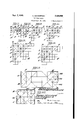
- -Figure lis asomewhatdiagrammatic view in horizontal section. of a building structure embodying the prnciplesof the invention the section being taken at approximatelythe level of the lowerchords-of the .roof trusses of the building;
ments themselves.
the angle plates. as are 'requiredgfor the,v diagonal connections'in the joints.
The arrangement shown in Figures-i4 and?, of the `drawirrgs is not-.employedin the embodiment illustrated in Figures 1 vto ,3, butthis type of connection Wouldbe made between the truss chord at one kof-4 the end walls of the structure and an abuttingstrut 2l Ior 22. Such a junction could be employed, for example, at the joint designated J2 in Figure 10 of the drawings. In this case the lower ,chord i6 ofthe end truss comprises the usual elements 23 and 21 and the strut 2 I, 22 is disposed with its endv resting upon the chord i6, or if there is no end trussaj similar connection could be made with the wall plate instead of a-truss chord.V `In order -torigidifyk the `ioint and to provide means for the attachment of the diagonal bracing elements anl angle plate has its vertical flange secured against the chord |16 by means of thebolt 575.v The horizontal upper flange of the angle piece V551s disposed beneath the strut 2l, 22 with its ends projecting laterally therefrom., Other anglewpieces -51 areapplied to the sidesof the strut 2|, 22 and are secured together through the struts by meansY of bolts 58.v The horizontal flanges of these angle pieces 58 overlap portions of the horizontal flanges of the angle piece 55 and aligned open:
yOf course, in the broader aspects of thepresent invention, the jointsbetween the trusses and the struts, and the application of the diagonal braces thereto, may be effected by anyother suitable lmeans, the speciiic arrangements-shown and described herein being chiefly for the pur-v pose of exemplifying an elicacious typejof joint and also as indicating the saving effected in the constructionfof the joints where no vdiagonals arev attached.k f A t present prices, the saving in connection costs at each joint whereall diagonal members are eliminated is from $2.50 to $5.00. This saving is in addition to the savings incidental to the elimination ofthe ,diagonalbracing ele- Now, in order to illustrate the effectiveness of the novel bracing arrangement and make fa comparison with the common bracing expedients of the prior art, reference Will be made to Figures 9 and l0 of the drawings taken in connection with certain diagrams forming parts fof Figures 2 and 3. Assuming a wind pressureA against one .of the sidewalls l0 of a rectangular building of the general arrangements shown in these figures, it will bew seen that the pressure against thewall surfacing .which is secured to the wall studding, tends to bend the studding which acts as a beam extending between the iioor and ceiling lines. wall goes directly to the floor line and half goes upward to the Aceiling or truss line. However, all of the wind which blows on the structure above the ceiling or truss level must be carried latzth'is level. This is shown graphically in Figures 2 Vand in which the-.height of the wall from thefground toY the lower truss chord is h.y and the height of the truss` itself is r. The width of the bay between columns l2 and the trusses l5. is w. Thus the magnitude ofthe wind force is expressed in the pounds persquare foot of the wind pressure, multiplied by one-half the story height plus the height from the ceiling to the prior art in Figure 9, it will be seen` that, ,assum-VV ing the wind pressure to be against the side Wall l@ at the upper portion of the gure, the y Therefore, half of the pressure on the topqofsthe truss', multiplied by the width of the,
portion of the; wall backed-up by the trussl in question.v This area is indicated by the shaded .rectangleinFigureZand-is equal to s div) If the lateral pressure or Aforce in lbs. per square foot is j, then the pressure p sustained by the end of one of the truss members, as indicated in Figures 1 9, and 10 of the drawings will be there are 8 bays in theside walls of the ,building and 9 lines of members perpendicularr` tothe'se' walls, the force in shear delivered from the bracing system to each end wall to sustain the'total force supplied to the side wall will be`4p'; While in the examples shown in Figures 9 and 10 the force in shear in each end wall'will be 3.51).
In order to make the explanation more real-f istie, rvit may be assumed that the ceiling height of the building is 2G ft. and the height of the archV truss roof is 9 ft. Then, if the spacing of the:
trusses is 18 ft." and the wind pressure 15 lbs'.
5130 lbs. y o o,
By referring to the diagram illustrating Vthe values for the stress set up in each of the struts, truss chord section, and diagonal bracing ele-v ments are as indicated in the drawings. Similarly, in Figure i0, with thewind pressure upon the side wall at the upper part of the figure,"
the various stresses set up in the truss struts and diagonal braces is also indicated. In Figure 10,y it will be noted that the diagonal elements which,
are active in sustaining the kstresses under the stated o conditions are indicated inksolid lines,Y
while those which are idle under ythe stated wind.
conditionsare shown in dotted lines. Obviously, if the wind direction were opposite, these indications would be reversed, and it'will be clearly understood that in cases where the wind is moving endwise of the building the stresses would be similarly and symmetrically distributed. Of course, when the wind blows yat an angle to the walls Aof the building the stresses Will be distributed' and calculated inaccordance with the perpendicular components of the forces,applied.`
The following tabulation willvery clearly show the savings of material and the better`clistribu` tion of stresses in the embodiment of the present invention illustrated in Figurel 10 as compared witl'rthe conventional arrangement of Figure 9:
i Figure 9 Figure l0 Maximum force in any one strutT- i l. 5P P Maximum force in any one diagonal.; 1.41P 1.41P Number of joints with diagonals attac 44 22 i Number of diagonal brace rods 44 24 It will beseen that although the maximumv force in any diagonal rod is the same in either case, ltheinaximun'rforce in a transverse strut is one) and one-half times the Value of Psc that.
the connections in the oldtype of construction many steelangle connected joints to be. provided for the attachment of the diagonal braces.- Furthermore, there are but slightly over half the number of diagonal brace rods necessary and yet the largest rod is no larger than the largest necessary to take the maximum stress in the 01d type of construction The earthquake or seismic force to be allowed for is commonly calculated quitesimilarly except that it is-based' upon the weight ofthe structure; for example, generally in structures of this type, this seismic force is assumed to be 8% of the weight of the structure at about the center of the first story plus an additional 8% of one half of vthe live load on the trusses.
It Will be seen that basically the present .inventioninvolves the provision of triangular. braced areas- W'thirn the cross section of the building whereby, in effect, triangular horizontal truss sectionsY are provided for transmitting the v stresses directly sustained by a wall of the building to other walls of the building,- either the one opposite the directly affected wall or the two end walls. whichfare perpendicular to the Wall against which the force is applied. In the case of the embodiment shown in Figure 1,` the triangular bracing areas are disposed centrally of the building.V and the force is transmitted from one wallv to another of the walls, other expedients such` as knee braced trusses or the like being used, if necessary, to sustain pressures applied endwise of theb-uilding.` l
In the embodiment shovvnin Figure 10, the triangular braced areas serve to' transmit the stress sustained by the side Wall. to the end walls I of the building. In this arrangement, a line of diagonalbracesextends from approximately the mid-points of the adjacent side and end Walls, andthe arrangements at the corners-of the building are subdivided by means of other diagonal braces, while the substantially loz'enged-shapedl area in the center ofthe building is free of diag'- onal-braces. Furthermore, it will be noted that in this specic arrangement, there are no crossed diagonals within 'any one rectangruar space. into which the area of the structure is divided.
However, these particular conditions hold' goed only'incases wherer the corner patterns do not lap each other as they do in certain of the other illustrated embodiments.
' In AFigures 'Il and 12v of the drawings there are l illustrated certain basic'patt'erns of corner brac.- ingV Which` comprise one of the essential features of the'present invention.
In Figure 11 one wall orthbulluing indicatedv rf at Ill) intersects with an adjacent wall H at right angles.` The parallel ytransverse elements. com,- prising either trusses l'or struts, which abut the walil'c and' the opposite wall (not shownl', are indicated at'72`. The opposite extending parallel elements which abut the Wall Il and the other opposite wall are designated by the reference numeral i3. In this arrangement the aligned diagonal bracing elements lliv form a line L Whichbounds the triangular bracing area-at the building corner in this embodiment. JIt Will be noted that the line L connects points on'the walls l0' and Hv each of which are spacedfromthe corner point' 16' bythe Width of two! bays- `.The corner network in this instance is completed by the diag.-y on'al element l'IT' which connects the wall areaI corner point l with the juncture 18 between` thetwo llra'ceslb.l It will be .seenfthat the'brac ingIv elements-and thewa'lls or boundaries off they building -Jarea in this exampleare-dividedV into two equllateral triangles, the bases of which form portions ofthe walls or .boundaries and certain sides of which comprise the bounding line L of theitriangular bracing network area, 1
l in Figure. 12 of the .drawings another elemental .former comer bracing is shown. In this case the walls lo and H are intersecterd by the bounding line' of braceslz"4 at points spacedl bythe Widtho three bays `from thefcorner 15. l In this casethere `are two-diagonal bracing elements' 11 which extend from: two joints 18 between the braces 'l5 to the points 6I and 82 which are spaced fromthe corner 'I6 by 'thewidth of 'one bay along each Wall.- l' '.lhese points are joined by another dlagonalslgwhlch completes the corner network. This diagonal may also b'edesignated L since it is the `first obliquellnefrom the corner 'I6V which intersects the walls I0 and Il. It will be seen that the network Vformed by the diagonals, comprises. one complete equilateral parallelogram flanked by two equilateral 'triangles adjacent the walls of boundaries I0 and H' and a small-trangle at the-far' corner of the arrangementr which triangle is bounded by the points 16, 8|, and 82 and is equal to onequarter ofthe area of the equil'ateral parallelogram. i f v,
yIn Figure lthere is shown an' amplification of the elemental arrangement illustrated in Figure 1I. Another bounding-line L1 is formed parallel with the line L .and forms a new boundary for the triangular area extending from apoint four bays from the corner T6 on the wall l0 to a point on the wall Il which is also four bays from the corner 16. The connecting diagonale 71 are added, thus completing `the corner network which in this-'case comprises two equilateralparallelograms n'anked by equilateral triangles and toppedbya pair of equi'lateral triangles similar to: the entire networkL of Figure Vl1. o In Figurele the arrangement of Figure I2 is amplified by the addition ofa further line L2 com'- posed'gof ve aligned diagonals and yconnecting points' onl the walls land: H which are respectively spaced from the corner '16 by the width of five bays 0neitherfwall. y
Figures I5 and lshcwy diagrammatically the extensionlo'f the elemental-arrangement of' Figure v11 to cover six `bays along each `Wall and the arrangement in Figure l2 to cover seven bays along each' Wall, respectively. Y I
Fory convenience of 'referencethe elemental ar'- rangement of Figure 11 willL be designated type II, the arrangement `of Figurev 12"V will be referred to astypeand tlleamplifledV networks shown in Figures *131,` 14, ll, and 16 will'b'ereierred to as types IV,A VVgmlf,` andVII, respectively.
Cbviously, buildings to which the invention may beapplied are subdivided into diiering num bers of rectangular areas, and their Walls into dilering numbers of bays', and the` exact arrangement 'of' bracings of--whatever type selected may varyv to some extent in each case. Also', the triangularv bracing networks may be disposed symmetrically in theA sameY relationship' with respect tol certain yint'ermedlate lines through a bundling,- as'with respect tothe outer walls of the each other' at that poma-or may overlap either ends; Type' III bracing is used, the'patterns beingspaced by the width of one bay. on one side and being contiguous at the ends.
In Figure 11 of the drawings, where there are eight bays along the ,sidewallsV and six along the end walls, the arrangement will be as illustrated, wherein the corner'pattern designated type IV is employed, the lines of diagonals which bound the triangular bracing areas meet at a single point at the center'of the longer walls, but these areas overlap by thewidth'of two bays on the end walls. "This causescertain of the diagonals of these overlapping, patterns tobe superposed as'shown at lill! in Figure 11. i y
In Figure 12 where there are sevenbays along the side walls andhonly've along the end walls and type 4III bracing pattern is used, the points of connection ofthe bounding'line ofvdiagonals with4 the side walls are spaced apart by the width of one bay asin the .case oi Figure 1 0, and the corner patterns overlap on the end walls by the width of one bay, forming the crossed diagonal patterns indicated. at l! in thesey bays. y In Figure` 19 of the drawings, a long narrow buildingV is shown having seven bays along the side walls and only three bays along the end walls. Ihe type III design of corner bracing is used, and t`, wil1 be seen that4 the patterns are spaced along the'side walls by the width of one bay, but that they overlap completely along the end walls, that is, by the width of the three bays comprisingsaid walls. vThis causes crossed patterns of bracing to occur in four of the triangular areas as indicated at |62 in Figure 19. In this .gure and also in Figure 20, the Iadjacent overlapping triangular patterns are indicated by' diierent chain lines so that they may be more readily distinguished. K In Figure 20 there is illustrated a horizontal planof a building which is nearly square having iive bays along the side walls and four bays along the end walls. Type III bracing pattern is employed 'and it will be seen that the corner networks overlap along the side walls by the width of Vone bay, yielding lcrossed diagonals as indi-` catedat lil-5, and they overlap by the width of two bays at the end walls, making superposed` diagonal braces necessary as indicated at ll'.Y
The various: adjustments Aof lthe basic designs are peculiar to the variations inthe horizontal sections of the buildings and the truss and strut distributions,but they do not depart substantially from the fundamental arrangements illusl tratedjand described herein in connection particularly with Figure` -10 of the drawings, and the savings in diagonal braces and the metallic joints for the diagonals are substantial. In the case of the arrangement shownin Figure 17 oi the drawarrangement shown in Figure 18, the number of i diagonals is. reduced from 40 to 24 and the mlm-.f
br of jointswith diagonals yfrom 40 to 24 as com'- pared withlthe prior art arrangements; In' Figure 19,k the number of diagonals is'reduced from 36 to 24 as compared with the corresponding prior art arrangement, and joints with diagonals are also reduced in number from 36 to 24. Similarly thel number of diagonals employed' in the ar' rangement shown in Figure 2l) is reducedfrom r28` to 211 and `the joints with diagonals reduced from 28 to'18 ascompared with the equivalent prior art structure. n A
It will be seen that by means of the present in'-v vention, there has been provided a-novel horizontalbracing arrangement by which more'effective support of a building against lateral applied force'smay be attained with a considerably less outlay'for materials and labor than in the case of conventional constructions.
At the same time, the novel arrangement rel sults Vin less concentration of stress in the individual members, which means that therei's less elastic deformation and less joint slip. More uniform standardized sizes of material is'ma'de possible andv therefore a greater duplication of details in the case of all members of the struc` ture. 'f
It isunderstood that various.` changes and mod-'- ications may be made inthe Vembodiment illus'- trated and described `herein without departing from the scope ofthe invention as defined by the following claims.
Having thus described the inventionh'what'lclaim as new and desire -to secure'by Letters A Patent is: l. In a rectangular building structure having one or more walls subject to horizontal forces,
a bracing system for transmitting such forces toY oppositewall and Idividing' said Walls into aplu'ralv ity cfr-bays of .approximately equal width, a series of other substantially parallel horizontal mem-A bers'extending at right angles to vthe members kof Athe'. rst ynamed series, connecting the' other twoopposed walls. and dividing them into a plurality ci bays of approximately equal Width,A said series of members also dividing the hori-v` zontalsec-tional area of the structureinto a plu-il rality `of Vrectangular spaces, means forming joints connecting the members of saidv rst series with those ofthe second series, and both of said series with the walls of the building, at their severalY points of intersection.. and elements rfor l sustaining tension stresses only extending' fdiag-` onally acrosscertain 0i said rectangularv Spaces ing area,'said area comprising a network of saidv diagonal elements which includes said limiting line of diagonal elements `and one or more addi`-' tional diagonal elements connected as described at the junction of the individual diagonal elements of said line, the aforesaid network ccm'- bracing system for .transmitting such ,forces'to other walls of the structure, said syst-em comprising a series of substantially parallel horizontal members extending fromone wall to the oppositewall and dividing sai-d walls into afplurality of bays of approximately, equalwidth, a series of other substantially parallelhorizontal members extending at right angles tothe members of the first named series, connecting the other two opposed walls, and dividing them into l a plurality of bays of approximately equal with, said series of members also dividing the horizontalsectionalarea of the structure intoA a plurality of rectangular spaces, 4meailsorming 4joints connecting the members of Vsaid first series with those of the second series, and :both of said series with the walls of the building, at their sevfv eral po-ints of intersection, and elementsfor sustaining tension stresses only extending diagonally across certain of said rectangular spaces and connecting certain of said joints at diagonally opposite corners of said spaces, a line of said diagonal tension elements extending from a point along one wall Whichis spaced from the corner of said buildin-g area by the width of three or tion of the individual diagonal elements of said line.
3. In a rectangular building structure having one or more walls subject to horizontal forces, a bracing system for transmitting such forces to other wallsV of the structure, said system comprising a series of substantially parallel ,horizontal members extending from one wall to the opposite wall and dividing said walls into a plu.- rality of bays of approximately equal width, a series of other substantially parallel horizontal members extending at right angles to the members of the first named series, connecting the other two opposed walls, and dividing them into a plurality of bays of approximately equal width, said series of members also dividing the horizontal sectional area of the structure into a plurality kof rectangular spaces, means forming joints connecting the members of said rst series with thosecof the second series, and both of said series with the walls of the building, at their several points of intersection, and elements' for sustaining tensicnstresses only extending Vdiagonally across certain of said rectangular spaces and connecting certain of said joints at diagonally opposite corners of said spaces, a plurality of parallel oblique lines of said diagonal tension elements extending respectively from-points along one wall spaced from the corner ofsaid buildin?,r area by the width of one kor more bays to corresponding points on the adjacent wall spaced from rthe corner by the same number of bays, the successive points of intersection of said walls and lines being spaced apart along said walls by the width of Vtwo bays, said lines of diagonal tension elements defining with said adjacent walls a trir angular bracing area, said area comprising a network of said diagonal elements which includes said limiting lines of diagonal elements and additional diagonal elements connected as described at the junction of the individual diagonal elements of said lines.
i 4. In a rectangular building structure having one or more walls subject to horizontal forces', a bracing system for transmitting such yforces to other walls of the structure, said system comprising a series of substantially parallel horizontal members extending from one wall to the'oppo-v site wall rand dividing said walls into a plurality of bays of approximately equal width, a series of other substantially parallel horizontal members extending at right angles to the members of the firstnamed series, connecting the other two opposed walls,` 4and dividing them into a plurality of bays of approximately equal width, said series of members also dividingv the horizontal sectional area of the structure into a plurality of rectangular spaces, means forming joints connecting the members of said rst series with those of the second series, and both of said series with the walls-of the building, at their several points of intersection, and elements for sustaining tension stresses only extending diagonally across certain of said rectangular spaces and connecting certain vof said joints at diagonally opposite corners of said spaces, said diagonal elements forming triangular bracing areas extending .from each corner of the building area along the adjacent sides, and each bracing area including a lline of said diagonal tension elements extending from a point along one wall which is spaced from the corner of said building area by the width of two or more bays to a pointon the adjacent wall spaced at the same number of bays from the corner, said area comprising anetwork of said diagonal elements which includes said limiting line ofvdiagonal elements and one or more 4additional diagonal elements connected as `described at the junction of the'individual diagonal el'ements of said line, the aforesaid network comprising the only ones of such diagonal tension elements employed at said corner. v
5. In a rectangular building structure having one or more walls subject to horizontal forces,`a bracing system for vtransmitting suchjorces to other walls of the structure, said system comprising a series of substantially parallel horizontal members extending from one wall to the opposite wall and dividing said walls into a plurality of bays of approximately equal width, a series of other substantially parallel horizontal members extending at right angles to the members of the first named series, connecting the other two opposed walls, and dividing them into a plurality of bays of approximately equal width, said series of members also dividing the horizontal sectional areas of the structure into a plurality of rectangular spaces, means forming joints connecting the members of said rst series with those of the second series, and both of said series with the walls of the building, at their several points of intersection, and elements for sustaining tension stresses only extending diagonally across certain of said rectangular spaces and connecting certain of said joints at diagonally opposite corners of said spaces, said diagonal elements forming triangular bracing areas extending from each corner of the building area along the adjacent sides, and each tension area including a plurality of parallel oblique lines of said diagonal bracing elements extending respectively from points along one wall spaced from thecorner of said building area by the Width of o-ne or more bays to corresponding points on the adjacent wall spaced from thecorner by the same number of bays, the successive points of intersection of said walls and lines being spaced apart along said walls by the Width of two bays, said area comprising arnet- Work` of; saidl diagonal I elements which includes said limiting lines of diagonal elements and addi-y tional diagonal elementsconnected as described at the junction of the individual diagonalelements ofsaid lines.' i. 6. In a rectangular building structure having one or morewalls subject to horizontal forces,v a braci-ng system for transmitting such forces to other Walls of the structure, said system comprising a series offsubstantially parallelhorizontal members yextending from one IWall toythe opposite Wall and dividing said Walls into a plurality of each. vcornerof..y the .building area along the: ad-
.bays of approximately equal Width, a series of other :substantially :parallel-horizontal members extending at'right angles to the members of the. iirst named series; connecting the other two opposed Walls,'and dividing theml into a plurality of bays of approximately equal width, said series of members also dividing the horizontal sectional areaof the structure into ai plurality 'of rectangularspaces, means forming-jointsconnecting the membersv onfsaidrst series with those of the second series, andboth of said series with the f Wallis of the building, at-,theirseveral points of intersection, and yelements for, sustaining tension 1 stresses only extendingdiagonally across certain'A ofrsaid rectangular spaces and connecting certain of -said bjoints at diagonally opposite corners' of saidslaces,V` said diagonal elements;` forming tri-- vangular bracing areasextendingfrom each corner ofthe building areaalong the adjacent sides, v
and eachbracing ,area lincluding a line of said diagonal tension velements extendingfrom a point along one Wall 'which is spaced from the corner of said building area bythe Width of tWo or more bays to a point on the adjacent Wall spaced at the'same number of'bays from the corner, said area' comprising a network of vsaid diagonal .elements which` includes said. limiting lineof diagonal elements and oneior more additional diagonal elements connected as describedat the junction rof the individual ldiag'onal elements of said'line, the aioresaid'netvvork comprising'the` only ones of such diagonalftension elements employed yat said cornerfcertainof 'thesides of said triangular areas which coincide with the sides of sfa'idvbuilding area being'of a length equal'to more than one-half of the length of said corresponding building sides, Whereby'said triangular areas'4 overlap atf'certain of their adjacentapexes.
. f ,7. I'ny a rectangular buildingr structure having one or more'walls subject to horizontal forces, a bracing system kior transmitting lsuch forces to other "Walls of the structure, said system comprising a series of 'substantially parallel horizontalmembers extendingt'from onewall to the opposits `vvall and dividing saidy Walls into a pluralseries ofl 'members' also.r dividing thefhorizontal sectional area" of the structure `into a plurality of rectangular spaces; means `forming joints connecting the members of'rsaid first series with those of the second series. and both of said series with the Walls of the building, at their several. points of intersection, and elements for sustain: ing tension stresses 1 only extending diagonally across certain of said rectangular spaces and connecting certain of said joints at diagonally oppo-.
site 'corners of said spaces, said diagonal elements forming triangular bracing areas extending from vjacent sides, and eachfbracing area including a plurality of parallel oblique` lines of said diagonal tension elements extending respectively from points along one Wall spaced .from the corner.of said lbuilding; area `by the width ofone .or more bays to corresponding points on the adjacent Wall spaced-from *thel corner by the saine number of bays,V the successive points of intersection of said Walls and lines being spaced Aapart along said Walls lvby vthe'vvidth of twobays, said area com'- prising a network'of said diagonal elements Which includes 4said limiting lines of vdiagonal elements and additional diagonal elements connected vas described at the' junctionxof the individual diagonal elements of `.said lines, certainV ofthe sides of said triangular areas-"Which coincide with the sides of said building areabeing of aiength equal to.' more than one-half ofthe lengthv of said corresponding building sides, Avvl'iereby said'triangular areas overlap certain of their adjacent apexes.
8. In a rectangularV building structure having extending fat right tangles .to lthe members of the rsty named series,A4 connecting the other two op.
posedv walls, and dividingitheminto aplurality of. baysiiof approximatelylequal Width, said series of members VValso dividing thehorizontal sectional area of the structure into a pluralityof rectangulargzspaces, means forming joints connecting the rrnernbers'ofsaid iirst serieswith those of the'second series; and Iboth of .said series with the walls ofjthe building, at their several pointsvof. inter- 'sectiongandx elements forjsustaining tension stresses onlyzextending diagonally acrosscertain of* said rectangular*spaces and connecting certain of said ,joints diagonally opposite corners of saidspaces,` a line of said diagonal tension elements-extendingfrom. lapoint yalong one Wall A Whichiisgspacednfrom .the corner ofsaid building area by tliewid-th of`=three or more baysto a point on the adjacent `wall spaced'at the same number Qflqbays from the corner, said line' of diagonal vbracing-y--elernentsdelning With said adjacent tvlls. a triangular-bracing.area, said area com- Y pris'ing a network of saiddiagonal elements which rity ofV bays'of approximately equal width, a series of other .substantially parallel horizontal members extending. at right angles'to the members .of the'rst named 'se'ries, connectingthe other two opposed Walls, and.;dividingv them into a plu-4 rality of bays V of approximately equal Width, said includes-said limiting'line of diagonalv elements and one' or more additional'. diagonalelements connected as described atthe junction'of the individualdiagonal elementsoi said line, the diagonal tension elements forming .with "themselves equal equilateral parallelograms; and rorr'nin'gx with the/Walls of said 'buildingareas triangleswhich are-"aliquot :parts of.r said parallelograms.
' 9. In a rectangular building structure havingA one or more walls subject to horizontal forc'a'a bracingssystem for transmitting- Lenen iorcestc y other :Walls VY of they structure,4 said system .cornprisingv a series of .substantially parallel horizon-I tal members extending' from one Wall tothe 'op-f posite'wall and'dividing said walls into a plural-- v vvity of bays of approximately e'qualwidth, afserie's' 'of .other substantially lparallel horizontall membersext'ending .at right anglesfto the members of f the. .rst named 'series,vconnectingthe other. tvvo` opposed Walls, and. dividing them into 'apluralit'yQo'fbays` of approximately equal Width, said` series of members also dividing the horizontal sectional: area of the structureintol a plurality; oi rectangular spaces; means; forming .jiointsl conneeting the members: or said firstl series@ with those of,` the second series, and both ofsaid series with the' walls'y @tithe building, at theirvseve'ral points of intersection, and elementsfor sustain:- ing* tension, stresses only extending`diagonally 'across certain or said rectangularspacesV andconnecting certain of said joints at diagonal'lyopposite-:corners ofsaid spaces, said diagonaleflernents forming. triangular bracing areas extending from each corn-erv of the building area along theadjacent sides,k and each bracingarea; including a plurality of parallel oblique lines. of saiclfdiag-k onal; tension elements extending' respectively from points along one Wall spaced from' the corner oi said building area by the width'of .one or more bays to corresponding points on the adjacenti Wall spaced from the corner by the same number of' bays,l the4 successive points of intersection of said' Walls` and linesY being spaced apart along said. Walls by the width of two bays, said areav comprising a networkr of saiddiagonal ele-v ments which includesv saict'limiting lines. of diagonalfelements and additional diagonalfe'lements connected as described at the junction 'of the individual-diagonal elementsof said'l lines,. the diagonal tension elements forming withth'emsellves equal equilateral; parallelograms and forming with the wal-ls'oi said'. buil-ding areas 'triangles f wllicl'l-x are aliquot parts ofsaid parail'elogra'msp` t L0. In a rectangular building structure having. one ormo-re walls subject toihorizontal iorces'a bracing system for transmitting such forces to otherl Walls of the-structure, said system comprisinga series 'of substantially parallel horizontal members extending from one Wall to theop'- of"rectanguiar spaces, means forming jointscon-A nectingfthe` members of said rst series with those of thesecond series, and both of 'said vseries with the walls of the building, at their several points of intersection, and elements foi` sustain` ing tension stresses only extendingl diagonally acrossv certain. of' said rectangular spaces and connecting certain of said joints-at diagonally oppositeV corners of said spaces, lsaid diagonal ele-i" vments forming triangular bracing areas extendingirom eaclr corner of lthe buildingA area' along the adjacent sides, and. each. bracing area includ-i-ngv a pluralityof," parallel oblique lines of said diagonal tension Aelements extending re-' spectively from points along one :wall `spaced from the corner of vsaid building area. by the Widtlr'of one or: more bays to corresponding: points on the'adjacent Wall spacedv from the corner bythe same number of bays, the successive points of' intersection Vof .said'walls and lines being spaced' apart along said Walls bythe width `of twobays, said area' comprising' a network of said diagonal elements which includessaid liml iting llines of diagonal elements and' additional diagonal elements connected as described at Vthe junction of the-individual diagonal elements of said lines, certain of, thesides of said triangular.' areas which coincide with the sides of saidbuildascenso 'ing one or more Walls subject to horizontal forcesJ a bracing system-for transmitting such forces to other Wallsk of the structure, said system comprising' a series of substantially parallel horizontal members extending from one Wall to the opposite wall 'and dividing said' walls into a f plurality of bays of approximately equal Width,
'-.- a plurality of bays of approximately equal width,
said series of members also dividing the horizontal' sectional area of the structure into a plu-` rality ofv rectangular spaces, means forming `joints connecting the'members of said'iirst yse-` ries with those of the second series, and both'of said Vseries Withf the Walls'` of the building,` at
their several points of intersection, and elements for sustaining' tension stresses only extending dlagonally across certain of said rectangular spaces l and connecting certain ofy said joints at diagonally opposite corners of said spaces, said diag.- onal tension elements forming triangular braced area-s, comprising in eiect horizontal triangular trusses, a wall subjectto said horizontal forces substantially comprising the side of jonev of said triangular braced areas.
l2 In a rectangular building structure havingV one'or lmore Walls'subject to horizontal forces, a bracing system for transmitting. such forces to other walls of the structuresaid sys-` n tem comprising a series of subtantially parallel horizontal member extending from one Wallto the'opposite wall and dividing said Walls` into a l kbers of the first vnamed series, connectingvthe other two opposed Walls, and dividing them intov a plurality of bays of approximately equalv width, said series 4of members also dividing .the horizontal sectional areav ofthe structure into a plurality of rectangular spaces, means formingV joints connecting the members of said rst series with those of the second series, andfboth of' said series withnthe Walls of thebuilding, at their v .several points of intersection, and elements for sustaining Atension'stresses only extending diagonally across certain of saidn rectangular spaces and connecting certain of said points at diagonally opposite corners of saidr spaces, said diagonal tension elements forming triangular braced areas,` comprising in effect horizontal triangular trusses, a Wall subject to said horizontal forces substantially comp-rising the side of one of said Itriangular truss areas,-the other sideslof said triangular areas being respectively comprised by .j
Priority Applications (1)
| Application Number | Priority Date | Filing Date | Title |
|---|---|---|---|
| US459702A US2329068A (en) | 1942-09-25 | 1942-09-25 | Building brace |
Applications Claiming Priority (1)
| Application Number | Priority Date | Filing Date | Title |
|---|---|---|---|
| US459702A US2329068A (en) | 1942-09-25 | 1942-09-25 | Building brace |
Publications (1)
| Publication Number | Publication Date |
|---|---|
| US2329068A true US2329068A (en) | 1943-09-07 |
Family
ID=23825829
Family Applications (1)
| Application Number | Title | Priority Date | Filing Date |
|---|---|---|---|
| US459702A Expired - Lifetime US2329068A (en) | 1942-09-25 | 1942-09-25 | Building brace |
Country Status (1)
| Country | Link |
|---|---|
| US (1) | US2329068A (en) |
Cited By (2)
| Publication number | Priority date | Publication date | Assignee | Title |
|---|---|---|---|---|
| US4344262A (en) * | 1972-12-08 | 1982-08-17 | Berman Herbert M | Long span structural frame |
| WO2010007476A1 (en) * | 2008-07-13 | 2010-01-21 | Iyad Mohamad Adnan Daadoush | Cubical structural system |
-
1942
- 1942-09-25 US US459702A patent/US2329068A/en not_active Expired - Lifetime
Cited By (2)
| Publication number | Priority date | Publication date | Assignee | Title |
|---|---|---|---|---|
| US4344262A (en) * | 1972-12-08 | 1982-08-17 | Berman Herbert M | Long span structural frame |
| WO2010007476A1 (en) * | 2008-07-13 | 2010-01-21 | Iyad Mohamad Adnan Daadoush | Cubical structural system |
Similar Documents
| Publication | Publication Date | Title |
|---|---|---|
| US2986241A (en) | Synergetic building construction | |
| JP2921882B2 (en) | Polygonal house | |
| US3396502A (en) | Suspension system for building construction | |
| GB553374A (en) | Improvements in and relating to the construction of bridges and other metal frame structures | |
| US3685229A (en) | Structural element for use in the construction of panels,modules,and building structures | |
| US2329068A (en) | Building brace | |
| US4438616A (en) | Space frames | |
| US2024001A (en) | Framed bridge or bridge-like structure | |
| US3762111A (en) | Fabricated construction of a house | |
| US3077961A (en) | Structural member for roof framework | |
| GB1310023A (en) | Building structures | |
| GB1011917A (en) | Improvements in or relating to prefabricated buildings | |
| US1753892A (en) | Space-covering structure, such as roofs, walls, and the like | |
| SU479863A1 (en) | Mesh tower | |
| US3474588A (en) | Open-work assembly and girder therefor | |
| US3367081A (en) | Space decks | |
| US3082576A (en) | Roof construction | |
| US4724647A (en) | Diagonal ceiling brace | |
| SU1649054A1 (en) | Assembly joint of spatial bar structure | |
| DE2652783C3 (en) | Wooden skeleton for a multi-storey building | |
| DE448790C (en) | Structure for subsidence areas dissolved in several articulated parts | |
| US3184014A (en) | Building construction | |
| US2392839A (en) | Building construction | |
| US3132444A (en) | Load-bearing structure | |
| GB570635A (en) | Improvements in or relating to reinforced concrete structures |