US2328362A - Power drive mechanism - Google Patents
Power drive mechanism Download PDFInfo
- Publication number
- US2328362A US2328362A US443502A US44350242A US2328362A US 2328362 A US2328362 A US 2328362A US 443502 A US443502 A US 443502A US 44350242 A US44350242 A US 44350242A US 2328362 A US2328362 A US 2328362A
- Authority
- US
- United States
- Prior art keywords
- power drive
- sprocket
- drive mechanism
- shaft
- hand
- Prior art date
- Legal status (The legal status is an assumption and is not a legal conclusion. Google has not performed a legal analysis and makes no representation as to the accuracy of the status listed.)
- Expired - Lifetime
Links
- 230000007246 mechanism Effects 0.000 title description 26
- 238000010276 construction Methods 0.000 description 4
- 238000005553 drilling Methods 0.000 description 3
- 235000000396 iron Nutrition 0.000 description 3
- 238000004519 manufacturing process Methods 0.000 description 1
Images

Classifications
-
- B—PERFORMING OPERATIONS; TRANSPORTING
- B66—HOISTING; LIFTING; HAULING
- B66C—CRANES; LOAD-ENGAGING ELEMENTS OR DEVICES FOR CRANES, CAPSTANS, WINCHES, OR TACKLES
- B66C9/00—Travelling gear incorporated in or fitted to trolleys or cranes
- B66C9/14—Trolley or crane travel drives
Definitions
- the invention relates to power drive mechanisms and refers more particularly to mechanisms attachable to load carrying devices of the hand-propelled type for converting the devices to the power propelled type.
- the invention has for an object to provide a power drive mechanism which is attachable to a hand-propelled load carrying device without drilling, cutting, or otherwise changing the device to adapt the Same for the power drive mechanism.
- the invention has for another object to provide a power drive mechanism readily attachable to and adapted to drive the propeller shaft of the hand propelling mechanism.
- the invention has for a further object to so construct the power drive mechanism that its driving unit is angularly adjustable about the propeller shaft of the hand propelling mechanism to take care of various conditions, including providing clearances for objects on the device or along its path of travel.
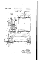
- Figure 1 is a front elevation of a power drive mechanism applied to a hand-propelled load carrying device
- Figure 2 is an enlarged cross section on the line 2-2 of Figure 1;
- Figure 3 is an enlarged front elevation. partly in section, of the power drive mechanism.
- the power drive mechanism embodying the invention is applicable to hand-propelled overhead load carrying devices, such as hand-propelled cranes, hoists, trolleys, and the like, and, as illustrated in the present instance, is attached to a hand-propelled single girder travelling crane.
- the crane comprises the end trucks l and 2, the single girder 3 in the nature of an I-beam extending between and supported on the end trucks and the electric hoist 4 supported on and adapted to travel along the lower flanges of the girder.
- the end trucks have the wheels 5 engaging the run-way rails 6 and supporting the crane, corresponding wheels of the end trucks being hand-propelled traction wheels for moving the crane along the run-way rails.
- the handpropelled mechanism comprises the propeller shaft and, more particularly, the squaring shaft 1 journaled in suitable bearings and having fixdriven member edly secured to its ends the pinions 8 which mesh with the gears 9 fixedly secured to the traction wheels coaxially therewith.
- the propeller shaft is adapted to be rotated by the grooved wheel [0 which is adapted to be rotated by an endless chain extending over the grooved wheel and depending to a position above the floor or ground where it can be readily manually operated by a person on the floor or ground.
- the construction of hand-propelled single girder travelling crane as thus far described is a standard construction made by a well-known manufacturing concern.
- the power drive mechanism comprises the driven member H which is formed of the transversely split sprocket l2 and the transversely split hub l3 attachable to the propeller or squaring shaft 1.
- the parting line between the two sections of the sprocket I2 is preferably arranged at right angles to the parting line between the two sections of the hub 13 and the sections of the sprocket are mounted on the sections of the hub and detachably secured to the radial flanges of the hub by the bolts M.
- the hub is suitably secured to the propeller or squaring shaft by the set screw I5.
- the power drive mechanism also comprises the unit I6 comprising the driving member ll formed of a sprocket operatively connected to the or sprocket l2 and also to the electric motor I8.
- the sprocket chain 19 extends over the sprockets l2 and IT for driving the former from the latter.
- the reduction gearing 20 between the sprocket l1 and the electric motor 18 is adapted to drive the former from the latter.
- is a support for the sprocket I1, electric motor l8 and reduction gearing 20, also serving as a housing for the reduction gearing.
- the support is readily attachable to the propeller or squaring shaft 1 and, as shown, is formed with the hubs 22 each of which is transversely split into sections encircling the propeller or squaring shaft and detachab y clamped to each other by the bolts 23.
- Sectional bearings 24 between the hubs and the propeller or squaring shaft facilitate rotation of the latter relative to the former.
- the support 25 is a sectional set collar fixedly secured to the propeller or squaring shaft 1 by the bolts 26 detachably securing the collar sections to each other.
- the set collar cooperates with the hub l3 to position the support 2
- the support has a housing chamber receiving the reduction gearing 20 and formed of the end wall 21 and the removable end plate 28, the wall being constructed for mounting the electric motor i8 thereon through the annular flange 29 of the electric motor and the bolts 30.
- the reduction gearing comprises the pinion 3
- the pinion 33 is journaled upon the pin 35 extending through the wall 21 and end plate 28 and the gear 32 is preferably mounted on and keyed or splined to the pinion 33.
- the sprocket I1 is preferably journaled upon the shaft of the electric motor beyond the pinion 3i and the gear 34 is mounted on and preferably keyed or splined to the sprocket H.
- the clamp 36 which is adjustably carried by the girder 3.
- the clamp as shown, comprises the generally semi-cylindrical band sections 3'! and 38 encircling the electric motor [8 and detachably secured together at corresponding ends by the bolts 39 and nuts 4
- angle iron 43 is an eye-bolt pivoted to corresponding ends of the band sections and extending between the angle irons 44 which are detachably clamped to the girder by the hook-bolts 45, 46 and 41 are nuts threaded on the eye-bolt and abutting the tops and bottoms of the angle irons for adjustably holding the eye-bolt at the desired height and 48 are bolts extending through the angle irons to hold the eye-bolt from swinging.
- the power drive mechanism is readily attachable to the crane without drilling, cutting, rebuilding, or otherwise changing the crane.
- the support for the driving sprocket, electric motor and reduction gearing therebetween serves to position these parts so that they may be angularly adjusted about the propeller or squaring shaft and the distance between the axes of the driving and driven sprockets maintained constant to provide for the use of a constant length sprocket chain.
- the driving unit may be angularly adjusted about the propeller or squaring shaft to take care of various conditions, including providing clearances for objects on the crane or along its path of travel.
- Power drive mechanism for attachment to a hand-propelled travelling crane comprising a driven member attachably secured to the squaring shaft of the hand propelling mechanism, a motor, a driving member operatively connected to said driven member and said motor, means attachably secured to the squaring shaft for predeterminedly positioning the axis of said driving member relative to the axis of said driven member, and means on the crane for holding said motor and said driving member from rotation about the squaring shaft.
- Power drive mechanism for attachment to a hand-propelled single girder travelling crane comprising a sprocket attachably mounted on the squaring shaft of the hand propelling mechanism, a unit comprising an electric motor, a sprocket operatively connected to said first mentioned sprocket, reduction gearing for driving said second mentioned sprocket from said motor, and a support for said motor, said second mentioned sprocket and said reduction gearing attachably secured to the squaring shaft for predeterminedly positioning the axis of said second mentioned sprocket relative to the axis of said first mentioned sprocket, and means on the girder of the crane for holding said unit from rotation about the squaring shaft.
- Power drive mechanism for attachment to a hand-propelled single girder travelling crane comprising a split sprocket attachably mounted on the squaring shaft of the hand propelling mechanism, a second sprocket operatively connected to said first mentioned sprocket, an electric motor, reduction gearing for driving said second sprocket from said electric motor, a support for said second sprocket, reduction gearing and motor also forming a housing for said reduction gearing, said support having split hubs attachably mounted on the squaring shaft, a band attachable to said motor, and an adjustable member carried by the girder of the crane and connected to said band for adjustably positioning said supp rt about the squaring shaft and relative to the girder.
Landscapes
- Engineering & Computer Science (AREA)
- Mechanical Engineering (AREA)
- Carriers, Traveling Bodies, And Overhead Traveling Cranes (AREA)
Description
Aug. 31, 1943. D. A. SCHAITBERGER 2,328,362
POWER DRIVE MECHANISM Filed May 18, 1942 2 Sheets-Sheet 1 INVENTOR. DANIEL A. SCHAITBERGER ATTORNEYS Aug. 31, 1943.
D. A. SCHAITBERGER POWER DRIVE MECHANISM Filed May 18, 1942 2 Sheets-Sheet 2 INVENTOR.
DANIEL A. SCHAITBERGER BY ATTORNEYS Patented Aug. 31, 1943 POWER DRIVE IHECHANISM Daniel A. Schaitbcrger, Detroit, Mich, assignor to Northern Engineering Works, Detroit, Mich., a
corporation of Michigan Application May 18, 1942, Serial No. 443,502
4 Claims.
The invention relates to power drive mechanisms and refers more particularly to mechanisms attachable to load carrying devices of the hand-propelled type for converting the devices to the power propelled type.
The invention has for an object to provide a power drive mechanism which is attachable to a hand-propelled load carrying device without drilling, cutting, or otherwise changing the device to adapt the Same for the power drive mechanism.
The invention has for another object to provide a power drive mechanism readily attachable to and adapted to drive the propeller shaft of the hand propelling mechanism.
The invention has for a further object to so construct the power drive mechanism that its driving unit is angularly adjustable about the propeller shaft of the hand propelling mechanism to take care of various conditions, including providing clearances for objects on the device or along its path of travel.
With these and other objects in view, the invention resides in the novel features of construction and combinations and arrangements of parts as more fully hereinafter set forth.
In the drawings:
Figure 1 is a front elevation of a power drive mechanism applied to a hand-propelled load carrying device;
Figure 2 is an enlarged cross section on the line 2-2 of Figure 1;
Figure 3 is an enlarged front elevation. partly in section, of the power drive mechanism.
The power drive mechanism embodying the invention is applicable to hand-propelled overhead load carrying devices, such as hand-propelled cranes, hoists, trolleys, and the like, and, as illustrated in the present instance, is attached to a hand-propelled single girder travelling crane.
The crane comprises the end trucks l and 2, the single girder 3 in the nature of an I-beam extending between and supported on the end trucks and the electric hoist 4 supported on and adapted to travel along the lower flanges of the girder. The end trucks have the wheels 5 engaging the run-way rails 6 and supporting the crane, corresponding wheels of the end trucks being hand-propelled traction wheels for moving the crane along the run-way rails. The handpropelled mechanism comprises the propeller shaft and, more particularly, the squaring shaft 1 journaled in suitable bearings and having fixdriven member edly secured to its ends the pinions 8 which mesh with the gears 9 fixedly secured to the traction wheels coaxially therewith. The propeller shaft is adapted to be rotated by the grooved wheel [0 which is adapted to be rotated by an endless chain extending over the grooved wheel and depending to a position above the floor or ground where it can be readily manually operated by a person on the floor or ground. The construction of hand-propelled single girder travelling crane as thus far described is a standard construction made by a well-known manufacturing concern.
For the purpose of converting the crane to the power-propelled type to facilitate its travel and to eliminate the hand-operated chain, I have provided a power drive mechanism which is readily attached to the crane without necessitating drilling, cutting, rebuilding, or otherwise changing the crane. In detail, the power drive mechanism comprises the driven member H which is formed of the transversely split sprocket l2 and the transversely split hub l3 attachable to the propeller or squaring shaft 1. The parting line between the two sections of the sprocket I2 is preferably arranged at right angles to the parting line between the two sections of the hub 13 and the sections of the sprocket are mounted on the sections of the hub and detachably secured to the radial flanges of the hub by the bolts M. The hub is suitably secured to the propeller or squaring shaft by the set screw I5. The power drive mechanism also comprises the unit I6 comprising the driving member ll formed of a sprocket operatively connected to the or sprocket l2 and also to the electric motor I8. The sprocket chain 19 extends over the sprockets l2 and IT for driving the former from the latter. The reduction gearing 20 between the sprocket l1 and the electric motor 18 is adapted to drive the former from the latter. 2| is a support for the sprocket I1, electric motor l8 and reduction gearing 20, also serving as a housing for the reduction gearing. The support is readily attachable to the propeller or squaring shaft 1 and, as shown, is formed with the hubs 22 each of which is transversely split into sections encircling the propeller or squaring shaft and detachab y clamped to each other by the bolts 23. Sectional bearings 24 between the hubs and the propeller or squaring shaft facilitate rotation of the latter relative to the former. 25 is a sectional set collar fixedly secured to the propeller or squaring shaft 1 by the bolts 26 detachably securing the collar sections to each other. The set collar cooperates with the hub l3 to position the support 2| axially relative to the propeller or squaring shaft. The support has a housing chamber receiving the reduction gearing 20 and formed of the end wall 21 and the removable end plate 28, the wall being constructed for mounting the electric motor i8 thereon through the annular flange 29 of the electric motor and the bolts 30. The reduction gearing comprises the pinion 3| secured to the shaft of the electric motor, the gear 32 meshing with the pinion 3i and driving the pinion 33 which meshes with the gear 34 for driving the sprocket IT. The pinion 33 is journaled upon the pin 35 extending through the wall 21 and end plate 28 and the gear 32 is preferably mounted on and keyed or splined to the pinion 33. The sprocket I1 is preferably journaled upon the shaft of the electric motor beyond the pinion 3i and the gear 34 is mounted on and preferably keyed or splined to the sprocket H.
To hold the driving unit from rotation about the propeller or squaring shaft, I have provided the clamp 36 which is adjustably carried by the girder 3. The clamp, as shown, comprises the generally semi-cylindrical band sections 3'! and 38 encircling the electric motor [8 and detachably secured together at corresponding ends by the bolts 39 and nuts 4|) and at the other corresponding ends by the bolts 4! and nuts 42. 43 is an eye-bolt pivoted to corresponding ends of the band sections and extending between the angle irons 44 which are detachably clamped to the girder by the hook- bolts 45, 46 and 41 are nuts threaded on the eye-bolt and abutting the tops and bottoms of the angle irons for adjustably holding the eye-bolt at the desired height and 48 are bolts extending through the angle irons to hold the eye-bolt from swinging.
With the above construction, the power drive mechanism is readily attachable to the crane without drilling, cutting, rebuilding, or otherwise changing the crane. The support for the driving sprocket, electric motor and reduction gearing therebetween serves to position these parts so that they may be angularly adjusted about the propeller or squaring shaft and the distance between the axes of the driving and driven sprockets maintained constant to provide for the use of a constant length sprocket chain. As a result, the driving unit may be angularly adjusted about the propeller or squaring shaft to take care of various conditions, including providing clearances for objects on the crane or along its path of travel.
What I claim as my invention is:
1. Power drive mechanism for attachment to a hand-propelled overhead load carrying device comprising a rotatable driven member attachably mounted on the propeller shaft of the hand propelling mechanism, an electric motor, a rotatable driving member operatively connected to said driven member and said motor, a support for said motor and said driving member attachable to and positioned by the propeller shaft to position the axis of said driving member in predetermined relation to the axis of said driven member, and means attachably secured to the load carrying device for holding said support from rotation about the propeller shaft.
2. Power drive mechanism for attachment to a hand-propelled travelling crane comprising a driven member attachably secured to the squaring shaft of the hand propelling mechanism, a motor, a driving member operatively connected to said driven member and said motor, means attachably secured to the squaring shaft for predeterminedly positioning the axis of said driving member relative to the axis of said driven member, and means on the crane for holding said motor and said driving member from rotation about the squaring shaft.
3. Power drive mechanism for attachment to a hand-propelled single girder travelling crane comprising a sprocket attachably mounted on the squaring shaft of the hand propelling mechanism, a unit comprising an electric motor, a sprocket operatively connected to said first mentioned sprocket, reduction gearing for driving said second mentioned sprocket from said motor, and a support for said motor, said second mentioned sprocket and said reduction gearing attachably secured to the squaring shaft for predeterminedly positioning the axis of said second mentioned sprocket relative to the axis of said first mentioned sprocket, and means on the girder of the crane for holding said unit from rotation about the squaring shaft.
4. Power drive mechanism for attachment to a hand-propelled single girder travelling crane comprising a split sprocket attachably mounted on the squaring shaft of the hand propelling mechanism, a second sprocket operatively connected to said first mentioned sprocket, an electric motor, reduction gearing for driving said second sprocket from said electric motor, a support for said second sprocket, reduction gearing and motor also forming a housing for said reduction gearing, said support having split hubs attachably mounted on the squaring shaft, a band attachable to said motor, and an adjustable member carried by the girder of the crane and connected to said band for adjustably positioning said supp rt about the squaring shaft and relative to the girder.
DANIEL A. SCHAITBERGER.
Priority Applications (1)
| Application Number | Priority Date | Filing Date | Title |
|---|---|---|---|
| US443502A US2328362A (en) | 1942-05-18 | 1942-05-18 | Power drive mechanism |
Applications Claiming Priority (1)
| Application Number | Priority Date | Filing Date | Title |
|---|---|---|---|
| US443502A US2328362A (en) | 1942-05-18 | 1942-05-18 | Power drive mechanism |
Publications (1)
| Publication Number | Publication Date |
|---|---|
| US2328362A true US2328362A (en) | 1943-08-31 |
Family
ID=23761039
Family Applications (1)
| Application Number | Title | Priority Date | Filing Date |
|---|---|---|---|
| US443502A Expired - Lifetime US2328362A (en) | 1942-05-18 | 1942-05-18 | Power drive mechanism |
Country Status (1)
| Country | Link |
|---|---|
| US (1) | US2328362A (en) |
Cited By (2)
| Publication number | Priority date | Publication date | Assignee | Title |
|---|---|---|---|---|
| US2932260A (en) * | 1955-12-22 | 1960-04-12 | Puma | Device for holding crane bridges or the like in register with the track |
| US20150219102A1 (en) * | 2012-08-25 | 2015-08-06 | Oerlikon Leybold Vacum Gmbh | Vacuum pump |
-
1942
- 1942-05-18 US US443502A patent/US2328362A/en not_active Expired - Lifetime
Cited By (2)
| Publication number | Priority date | Publication date | Assignee | Title |
|---|---|---|---|---|
| US2932260A (en) * | 1955-12-22 | 1960-04-12 | Puma | Device for holding crane bridges or the like in register with the track |
| US20150219102A1 (en) * | 2012-08-25 | 2015-08-06 | Oerlikon Leybold Vacum Gmbh | Vacuum pump |
Similar Documents
| Publication | Publication Date | Title |
|---|---|---|
| US3313365A (en) | Two-wheeled motor vehicle | |
| US2608163A (en) | Monorail tractor | |
| US1917053A (en) | Portable crane | |
| US3543690A (en) | Wheel or drum drives | |
| US2328362A (en) | Power drive mechanism | |
| US2989007A (en) | Railway car mover | |
| US2752120A (en) | Precision load-positioning device for cranes | |
| US2500168A (en) | Vehicle supported tool and wheel drive control thereby | |
| US2993605A (en) | Loading and unloading crane | |
| GB1098146A (en) | Travel gear for cranes and trolleys | |
| CN110304545B (en) | Lower-rotation electromagnetic bridge crane | |
| US1209209A (en) | Motor-truck. | |
| US3978882A (en) | Mover unit for irrigation line | |
| US2408507A (en) | Steering drive mechanism for driven wheels | |
| US997934A (en) | Crane. | |
| US2282985A (en) | Motor driven trolley | |
| US402378A (en) | Wrecking-car | |
| CN208249707U (en) | A kind of multi-purpose wheel group of cucurbit | |
| US1350648A (en) | Trolley | |
| GB1061305A (en) | An overhead crane | |
| US1403598A (en) | Reduction gearing for cranes and hoists | |
| CN117383429A (en) | Forging flange hoist and mount processing is with tipping arrangement | |
| DE479800C (en) | Undercarriage for monorail trolleys designed for driving through tight curves | |
| CN215238162U (en) | A subtract heavy cutting trolley for new forms of energy trailer girder | |
| US2706010A (en) | Steering means for heavy duty vehicles |