US2294100A - Automatic oscillator frequency control system - Google Patents
Automatic oscillator frequency control system Download PDFInfo
- Publication number
- US2294100A US2294100A US4793A US479335A US2294100A US 2294100 A US2294100 A US 2294100A US 4793 A US4793 A US 4793A US 479335 A US479335 A US 479335A US 2294100 A US2294100 A US 2294100A
- Authority
- US
- United States
- Prior art keywords
- frequency
- circuit
- tube
- control
- network
- Prior art date
- Legal status (The legal status is an assumption and is not a legal conclusion. Google has not performed a legal analysis and makes no representation as to the accuracy of the status listed.)
- Expired - Lifetime
Links
Images


Classifications
-
- D—TEXTILES; PAPER
- D06—TREATMENT OF TEXTILES OR THE LIKE; LAUNDERING; FLEXIBLE MATERIALS NOT OTHERWISE PROVIDED FOR
- D06B—TREATING TEXTILE MATERIALS USING LIQUIDS, GASES OR VAPOURS
- D06B3/00—Passing of textile materials through liquids, gases or vapours to effect treatment, e.g. washing, dyeing, bleaching, sizing, impregnating
- D06B3/10—Passing of textile materials through liquids, gases or vapours to effect treatment, e.g. washing, dyeing, bleaching, sizing, impregnating of fabrics
- D06B3/16—Passing of textile materials through liquids, gases or vapours to effect treatment, e.g. washing, dyeing, bleaching, sizing, impregnating of fabrics in superimposed, i.e. stack-packed, form
-
- H—ELECTRICITY
- H03—ELECTRONIC CIRCUITRY
- H03J—TUNING RESONANT CIRCUITS; SELECTING RESONANT CIRCUITS
- H03J7/00—Automatic frequency control; Automatic scanning over a band of frequencies
- H03J7/02—Automatic frequency control
- H03J7/04—Automatic frequency control where the frequency control is accomplished by varying the electrical characteristics of a non-mechanically adjustable element or where the nature of the frequency controlling element is not significant
- H03J7/042—Automatic frequency control where the frequency control is accomplished by varying the electrical characteristics of a non-mechanically adjustable element or where the nature of the frequency controlling element is not significant with reactance tube
-
- D—TEXTILES; PAPER
- D06—TREATMENT OF TEXTILES OR THE LIKE; LAUNDERING; FLEXIBLE MATERIALS NOT OTHERWISE PROVIDED FOR
- D06B—TREATING TEXTILE MATERIALS USING LIQUIDS, GASES OR VAPOURS
- D06B2700/00—Treating of textile materials, e.g. bleaching, dyeing, mercerising, impregnating, washing; Fulling of fabrics
- D06B2700/09—Apparatus for passing open width fabrics through bleaching, washing or dyeing liquid
- D06B2700/095—Apparatus for passing open width fabrics through bleaching, washing or dyeing liquid for continuous treatment of open width fabrics, in which the fabric is guided without tension, e.g. superimposed or festooned, in order to extend the duration of treatment
Definitions
- My present invention relates to superheterodyne receivers, and more particularly to improved methods of, and means for, automatically stabilizing the frequency of the local oscillator of a receiver of the superheterodyne type.
- the modern superheterodyne receiver is often used under conditions such that the local oscillator frequency, at any setting of the manually operated tuner, tends to shift; Local oscillator frequency shift may be due to thermal changes as well as line voltage fluctuations. It is inherent in the superheterodyne principle that the accuracy With which tuning must be performed and maintained is directly proportional to the signal frequency. Present day short wave super- Densation. At 20 megacycles local oscillator sinus iations due to thermal effects and line voltage fluctuations amount to many kilocycles; in fact, frequency drifts of 40 or 50 k. c. are too often encountered.
- AFC Automatic frequency control
- the AFC system has many uses. Fine manual tuning required in high fidelity receivefs to obtain best results could be avoided with such a system.
- the AFC in general, may be said to be highly desirable for use in a superheterodyne receiver employed in a manner Such that accurate tuning is important. In connection with remote tuning control systems an AFC system will be found valuable in providing the final adjustment that the remote control Ysystem is unable to effect'.
- an AFC system for a superheterodyne receiver should comprise a device, having frequency discrimination, which is capa ble of producing a control bias dependent upon the frequency of the intermediate frequency carrier, and an electronic local oscillator frequency control network, operated by the control bias, for adjusting the local oscillator frequency in Va sense such that it differs from a desired signal frequency by the established intermediate frequency.
- each of the circuits hereinafter disclosed includes this discriminating control bias generator, and a fre'- quency control unit provided with an electronic device regulated by the control bias.
- the control includes a discriminator network comprising a pair of differentially connected rectiers which are mistuned by equal amounts above and below the mid-channel frequency of the intermediate frequency band; the discriminator functioning to provide a direct current bias voltage which is dependent upon the mid-channel frequency, and the bias voltage being utilized to Vary an electrical characteristic of an electron discharge device in a manner such that the local oscillator frequency is adjusted to a desired value.
- Another important object of my invention is to provide a system for automatically varying the frequency of an oscillator in a desired manner in response to the variations of a bias voltage generated by a network utilizing energy derived from the oscillator, the frequency varying system comprising a device for adjusting the reactance of the oscillator tank circuit without changing the load upon the latter.
- Another object of the invention may be said to be the provision of a novel method of frequency control of the local oscillator of a superheterodyne receiver, the method including the steps of impressing the intermediate frequency energy upon a discriminator network capable of furnishing a direct current voltage whose magnitude is dependent upon the carrier frequency of said energy, and the direct current voltage being utilized to Vary an electrode bias of an electron discharge tube employed to vary the resonant frequency of the local oscillator tank circuit.
- Still another object of the invention is to improve automatic frequency control systems for superheterodyne receivers, the improvement comprising the reduction of the intermediate frequency to a lower frequency, the derivation from the lower intermediate frequency energy of a control bias dependent in magnitude upon the lower frequency, and the employment of the control bias to regulate the magnitude of an electronic reactance in a sense to adjust the local oscillator frequency to a desired Value.
- Still other objects of the invention are to improve generally the eficiency of tuning of superheterodyne receivers, whether of the broadcast or short wave type, and more especially to provide automatic local oscillator frequency control systems for such receivers which are not only durable and reliable in operation, but readily manufactured and assembled in radio receivers.
- Fig. 1 shows one embodiment of the invention
- Fig. 2 illustrates a modification
- Fig. 3 is a graphic analysis of the response characteristics of the discriminator in Fig. 2,
- Fig. 4 graphically portrays the operation of the AFC system
- Figs. 5 and 6 show two modifications of the discriminator network used in Fig. 1,
- Figs. 7, 8, 9 and 10 show four modifications of the local oscillator frequency control device used in Fig. 1,
- Fig. 11 shows a modified form of an AFC system
- Fig. 12 schematically represents an AFC system applied to a superheterodyne receiver utilizing triple detection.
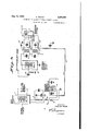
- Fig. 1 a circuit diagram of a superheterodyne receiver employing an AFC system.
- 'Ihe receiver is of a conventional type well known to those skilled in the art, and comprises a signal collector A, such as a grounded antenna circuit, coupled to a radio frequency amplifier having a variable tuning condenser device I in its input network.
- the amplifier may consist of more than one stage, and in such case the input of each stage would include a variable tuning condenser.
- the amplifier output is coupled to the tunable signal input circuit of the converter network, the input circuit including the variable tuning condenser 2.
- the converter network comprises a tube 3 known in the art as a pentagrid converter tube, also designated as a 2A7 type tube (or 6A? when used for automobile receivers); the tube is designed to perform simultaneously the functions of a first detector and local oscillator. Since the particular construction of tube 3, and its circuits, is not a part of this invention, only a brief description will be given of the circuits thereof.
- the tunable signal circuit of tube 3 is connected between the signal grid and the grounded cathode.
- the local oscillator section of the network comprises the local oscillator tank circuit 4 connected between the grounded cathode and the first grid functioning as the local oscillator grid.
- the second grid of tube 3 is magnetically coupled to the coil 5 of the tank circuit 4, and the second grid therefore functions as the oscillator anode.
- the third and fifth grids act as screen grids for the fourth, or signal, grid.
- the resonant circuit 6 disposed in the plate circuit of tube 3 is tuned to the operating intermediate frequency.
- I'he tank circuit 4 includes in addition to the variable tuning condenser l, the padding condensers 8, 9 which function to keep the tuning of the tank circuit 4 tracked with that of the signal circuits.
- the rotors of condensers I, 2, I are arranged for mechanical uni-control, and the dotted lines Ill represent such control.
- a "manual tuner knob II is used to adjust the rotors from the operating panel of the receiver. It is sufficient for the purposes of this application to explain that the condenser 'I tunes the tank circuit 4 through an oscillator frequency range differing at all times from the common signal frequency range of the amplifier and converter input circuits by the frequency of the circuit 5.
- the operating I. F. is assumed to be 450 k. c. It is to be clearly understood, however, that in place of the composite converter network there may be employed independent rst detector yand local oscillator tubes in a manner well known in the art.
- the signal frequency range may be the broadcast range, or it may be a short wave band.
- the intermediate frequency energy in circuit 6 is transmitted to the diode second detector circuit of multiple duty tube I2 through a network including an I. F. amplifier.
- the latter may include one, or more, amplification stages,
- vand is provided with an input transformer M1 having its primary and secondary circuits each resonated to the intermediate frequency; the output transformer M2 is similarly designed. Both transformers are designed to pass substantially uniformly a band of frequencies including the carrier and its modulation side band frequencies.
- the tuned secondary circuit I3 of transformer M2 is the input circuit of the diode second detector network.
- the tube I2 is of the duplex diode-triode type, also well known in the art as a tube of the 55 or 2A6 type; although it is to be understood that a pentode section may be used in place of the triode section of tube I2 (2B7 and 85 types).
- the diode anodes of tube I2 are strapped together, and connected to the cathode side of grounded bias resistor I 4 through a path including circuit I3 and load resistor I5, the latter being shunted by a radio frequency by-pass condenser I6.
- the triode section of tube I 2 has its control grid coupled to a desired point on load resistor I5 for deriving therefrom the audio component of the rectified intermediate frequency current.
- the amplified audio component in the plate circuit of tube I2 is then utilized in any desired manner.
- the direct current component of the voltage developed across resistor I5 is used for AVC purposes. This may be accomplished in any manner well known in the art.
- the lead I1 designated as AVC
- AVC is shown connected from the diode anode side of resistor I5 to the signal grid circuits of the radio frequency amplifier, the converter, and the intermediate frequency amplifier.
- the usual pulsating current filter elements I8, comprising a resistor and condenser, are disposed in the AVC connection.
- the signal grids of the controlled tubes are biased increasingly negative thereby reducing the gain of these controlled tubes. In this way the signal input to the second detector is maintained substantially constant over a wide range of signal amplitude variation at the antenna A.
- the controlled tubes can be progressively decreased in AVC bias.
- AVC bias may be derived from a separate diode rectifier; or from a point preceding the detector input circuit I3 whereby there will -be less selectivity to the AVC rectifier than to the detector.
- the converter I 9 is of the same type as that shown in connection with tube 3.
- the I. F. energy is impressed upon the signal grid through coupling condenser 20, and the local oscillation network (not shown) is tuned to a frequency of 500 k. c.
- the plate circuit of tube I9 a reduced I. F. of 50 k. c.
- the plate circuit of network I9 is coupled to the frequency discriminator network, the latter including an electron discharge tube of the duo-diode type.
- the tube 2I may be of the type shown in connection with the tube I2; in that case the grid and plate will be left free and only the diode anodes 22 and 22 are used.
- the plate circuit of tube I9 includes a pair of coils 23, 24 arranged in series. Coil 23 is coupled to resonant circuit 23'; the latter is tuned to one side of the I. F. of 50 k. c. by a predetermined frequency amount. Thus, circuit 23 is tuned to 49 k. c. Coil 24 is coupled to resonant circuit 24', the latter being tuned to the other side of the I. F., as for example to 51 k. c.
- the diode anode 22 is connected to the cathode of tube 2l through a series path including circuit 23 and resistor 25, the latter being shunted by a by-pass condenser, and the low alternating current side of circuit 23' being grounded.
- the diode anode 22 is connected to the cathode of tube 2I through a series path including circuit 24 and resistor 26, the latter being shunted by a by-pass condenser.
- the anode side of resistor 26 has connected to it a lead 21, designated as AFC; the lead comprising the path through which the control bias developed in the discriminator is applied to the electronic frequency control device.
- the lead 21 includes a resistor-con- H El of the carrier.
- denser network 28 which functions to suppress pulsating components in the control voltage transmitted through lead 21.
- a grounded switch 29 is connected to lead 21, and its function will be explained in detail at a later point.
- the device which functions to change the tuning of the tank circuit 4 comprises an electronic'l reactance element. It includes an electron discharge tube 30, which may be, for example, of. the screen grid type. A bleeder resistor 3
- the lead 21 is connected to the control grid of tube 30 through a resistor 32, and a condenser 33 of a predermined magnitude is connected between the control grid and anode of the tube.
- the control grid of the latter is also connected to the oscillator grid side of tank circuit 4 through a blocking condenser 34.
- the frequency discriminator itself is shown as comprising a pair of differentially connected diode rectifiers, the rectifiers being mistuned by equal amounts above and below the mid-channel frequency.
- the output of the network depends solely on frequency A change in carrier amplitude in that case only affects the sensitivity of the control action. In spite of this a satisfactory AVC system is desirable.
- the diode rec- .tiflers of the discriminator are connected differentially. That is to say, the difference of the rectifier outputs is utilized as the control bias to be transmitted through lead 21.
- diode rectiers it is possible to utilize in the balanced detector arrangement a pair of plate circuit detectors arranged in push-pull. However, it is more desirable to employ diode rectiers, because such an arrangement gives the difference in output directly.
- the point on resistor Zt to which lead 21 is connected is at a negative direct current potential with respect to ground when the input from circuit 2li is greater than that from circuit 23', and it will be positive with respect to ground in the reverse case.
- the inputs to the two rectiflers balance, and the point on resistor 26 to which lead 27 is connected will, therefore, be at ground potential. Accordingly it will be seen that the magnitude and polarity, with respect to ground, of the voltage of point Z on resistor 23 is wholly dependent upon the frequency value of the intermediate frequency energy produced in the plate circuit of tube I9.
- the device which changes the frequency of the tank circuit 4 is shown in the system of Fig. 1 as being of the type comprising an electron dis charge tube whose control grid to cathode capacity is utilized as a tuning condenser across tank circuit 4.
- the effect of the condenser 33 connected between the control grid and anode of tube 39 is to augment the capacitative magnitude of the control grid to cathode capacity of tube 30. It has been shown that in such a network, variation of the bias of the control grid results in a variation in the magnitude of the control grid to cathode capacity.
- the signal frequency to which the set is tuned is 1500 k. c.
- the frequency of the tank circuit 4 which is required in the production of the 450 k. c. I. F. is 1950 k. c.
- the frequency of tank circuit 4 changes to 1951 k. c.
- the second frequency changer is operating with a local oscillator frequency of 500 k. c.
- the second intermediate frequency energy, produced in the plate circuit of tube I9 will have a frequency of 49 k. c. Since this frequency of 49 k. c. is that of the circuit 23", the point Z will have a direct current potential which is positive with respect to ground, due to rectification in the rectifier circuit including diode anode 22.
- the bias of the control grid of tube 39 will be positive thereby increasing the gain of tube 3D, and increasing the magnitude of the control grid to cathode capacity of tube 30.
- An increase in this control grid to cathode capacity magnitude results in an increase in the total capacity in the tank circuit 4; it therefore follows that the frequency of the tank circuit will be reduced.
- the constants of the oscillator frequency control device are so chosen that a change in frequency of the tank circuit away from the desired frequency value will result in the production of control bias at point Z in the discriminator network suiicient in magnitude to vary the control grid to cathode capacity of tube 30 in that sense which will restore the tank circuit frequency to the desired value.
- control grid to cathode capacity of tube 30 will be increased to such a point that the frequency of the tank circuit 4 will be decreased from 1951 k. c. to 1950 k. c.
- the control grid to cathode capacity of tube 30 will be increased to such a point that the frequency of the tank circuit 4 will be decreased from 1951 k. c. to 1950 k. c.
- a practical difficulty of the receiving system shown in Fig. l is found in the difficulty of dislodging a strong signal to make way for a weaker one on a closely adjacent channel, without having the weaker station jump right across the band to disappear on the other side.
- the switch 29 is used; the function of the switch is to ground the bias voltage derived from point Z, and render the AFC system inoperative during tuning. After the signal has been tuned in the switch 29 may be opened, and the ground connection removed.
- the manner of closing switch 29 during tuning depends upon the construction of the controls of the receiver. If there are too many operating controls on the panel of the receiver, it will be advisable to mechanically couple switch 29 with the tuning knob ll so that the switch 29 will be automatically closed when the operators hand moves the tuning knob.
- This is schematically illustrated in Fig. 1 by the dotted line H11. Reference is made to U. S. P. 2,038,332, issued to E. Zadig, for an illustration of such a mechanism.
- the tuning knob may be depressible against a spring to close switch 29, and rotary motion of the tuning knob then instituted to vary the position of the rotors of the tuning condensers.
- Any other mechanical arrangement can be employed to keep the switch 29 closed during tuning of the receiver. If there are not many controls on the receiver panel, the switch 29 may be operated as a separate switch to be used only before tuning from one station to another one.
- Fig. 2 there is shown a modification of the superheterodyne receiver system shown in Fig. 1, only the AFC circuit details being shown in detail. It is to be understood that except for the AFC system, the receiver is substantially the same as that shown in Fig. 1. To preserve simplicity of description, appropriate designations are used by way of reference to the omitted circuit networks of the receiver.
- the receiving system shown in Fig. 2 was found satisfactory in operation, and was employed for receiving short wave signals of a frequency of thel order of '7500 k. c.
- the I. F. employed was 450 k. c., but the second frequency changer employed a local oscillation of 400 k. c. to produce the second I. F. of 50 k. c.
- the frequency discriminator network in this modification composed a pair of resonant circuits 40 and 4I arranged in series in the plate circuit of the second frequency changer tube i9.
- the circuit 40 was tuned in this case to 5l k. c., while the circuit 41 was tuned to 49 k. c.
- was connected to the cathode thereof through a path which included in series coil d' and the load resistor 25.
- the diode anode 22 was connected to the cathode of tube 2
- Coil 4t was coupled to circuit 40, while coil 4
- the frequency discriminator network of the AFC system of Fig. 2 differs from that shown in Fig. 1, in that the plate circuit of the frequency changer tube I9 includes the mistuned circuits feeding the differentially connected diode rectifiers.
- the oscillator frequency control device is substantially diiferent from that shown in Fig. 1.
- this type of control device there is employed an electron discharge tube 42 of the triode type, and the control bias produced at point Z is utilized to vary the cathode resistance of tube 42.
- Variation of the cathode resistance of tube l2 results in a variation of the reactance of the tank circuit This was accomplished by magnetically coupling a coil lf3, disposed in the grounded cathode lead of tube 42, to the feedback coil d@ of the first frequency changer tube 3.
- This arrangement is equivalent to more or less short-circuited turns loosely coupled to the inductance coil in the tank circuit d.
- the frequency change of the tank circuit 4 occurs because the effective inductance of the tank circuit is varied by the bias change on control tube 42.
- the leakage inductance of the coil 43 (turns not 100 percent coupled to l) is in series with the variable cathode resistance of 32. This is equivalent to throwing more inductive reactance across the coil when the negative bias is reduced, which raises the frequency, and vice versa. If the series reactance is a condenser, we have capacitive reactance across the tank coil, and reducing the negative bias lowers the frequency.
- Fig. 3 shows the response characteristic of each of the rectiflers (dotted lines). It, also, shows the differential, or net output, response of the network (full line curve).
- the solid line curve of Fig. 3 is a representation of the variation of AFC bias with frequency of the signal energy impressed on the discriminator.
- AFC bias generated by the differential rectifier network varies according to an S-shaped curve similar in form to dash line curve ai to d1.
- the total effective capacity is related to oscillator frequency by the nearly straight line az--da A portion of this total is physically present, not due to variations in the control tube, and variable, for example, only by manual means.
- This physical capacity is the difference between the total capacity and that thrown into the tank circuit by the control tube, and is represented by the solid curve, a2b2-c2-d2. This curve may be regarded as the control characteristic of the system.
- the oscillator frequency. and with it the I. F. carrier frequency increases progressively until the point a2 is reached. Thereafter instability occurs; for an increase in frequency brings about a decrease in total capacity by means of the AFC action which further increases the frequency, and so on. What happens is that the I. F. carrier frequency jumps abruptly to as. Thereafter operation is stable until c2 is reached, at which point a second jump occurs to c3. Traversing the band in the opposite direction the jumps occur at d2 to d, and at b2 to b3. Throughout the segment bzcz stable operation occurs, and it is here that the desired control obtains.
- the ratio of the slope of D202 to that of the straight line azdz is the sensitivity of the control; this slope represents the ratio of a potential variation in the (uncontrolled) oscillator frequency to that which actually occurs when the control is operative.
- the local oscillator frequency might be changed by as much as 200 k. c. for a 10 percent change in Gm of the-control tube.
- this 10 percent change requires a change of grid bias of almost exactly 0.4 Volt. I have found, using only fair coils peaked l0 k. c, apart at an I. F. of 450 k. c., that 10 volts variation in AFC bias from peak to peak is readily obtainable without overloading. On this basis, a Vcontrol sensitivity of 500 to 1 is conservatively possible.
- the discriminator rectifier connections are reversed, the double kink in the control characteristic is inverted, and the two sides of the band become regions of stability, with instability over the center. Control obtains on the two edges of the band, and the I. F. carrier can be made to jump from one edge to the other, but will not remain in the center. This, also, occurs with the properly poled connections, if the signal is tuned in at the image position.
- the present invention is not limited to the driving of the discriminator network as shown in Figs. 1 and 2.
- Figs. 5 and 6 are shown two different modifications of this portion of the AFC system.
- Fig. 5 shows the tuned diode rectifiers of Fig. l supplied with signal energy from the I. F. amplifier through separate driver tubes 50, 5l.
- the I. F. energy is supplied to amplifier 50 for amplification and subsequent impression on the tuned circuit 23'; amplifier 5I functioning to amplify I. F. energy prior to impression on tuned circuit 24.
- the discriminator network of Fig. 5 differs from that shown in Fig. 1 in that the I. F. is not reduced to a lower value.
- Fig. 6 there is shown an arrangement wherein the plate circuit of the last I. F. amplifier includes in series the primaries feeding tuned circuits I3, 23' and 24.
- the I. F. amplier may use, in this case, a 58 type tube having a high Rp. This mode of connection can be used as common coupling effects do not interfere with the desired discrimination between higher and lower frequencies.
- the I. F. is not reduced in value as in Figs. 1 and 2.
- the local oscillator reactance changer unit may be varied in construction.
- Figs. 1 and 2 show two different forms of reactance changers.
- Figs. 7 to 10 inclusive illustrate further modified arrangements which may be employed for the desired function.
- the tank circuit is that shown in either Fig. 1 or Fig. 2, and that the AFC bias may be derived from the discriminator networks shown in the latter systems, or those shown in Figs. 5 and 6.
- the frequency control tube has its plate impedance vary with the bias upon the grid.
- the frequency change of the tank circuit, in kilocycles, for a given proportionate variation in Rp is independent of frequency, and is xed by the time constant of Rp and the tank tuning capacity. If the latter is made as small as possible, for example of the order of mmf., and the Rp of the tube is 10,000 ohms, a ten percent change in the latter will produce a frequency shift of 20 k. c.
- the frequency control tube in Fig. 8 has its Rm 1 (mutual or trans-reslstance G- and Rp utilized in shunt combination to give a lower minimum value of variable tube resistance.
- the plate and grid are by-passed to ground, while the cathode is connected to the high alternating potential side of the tank circuit through condenser 60.
- connects the cathode to ground. If the tube Rm is thus utilized instead of the Rp its center value may be of the order of 1000 ohms, and the same percentage change in resistance will give a frequency shift of 200 k. c.
- the mean frequency should be large compared with the shift.
- Fig, 10 The arrangement in Fig, 10 is equivalent to that in Fig. 8.
- the cathode of the control tube is grounded, and the plate and grid, connected by the large blocking condenser 62, are connected to the high alternating potential side of the oscillator tank circuit through condenser 60.
- the Rm of the control tube is here utilized instead of the Rp.
- the frequency control variant in Fig. 9 is intended to be a fixed reactance in series with a variable resistance of approximately equal magnitude, (as in Fig. 7); but in Fig. 9 the variable resistance is l/(Gm-i-Gp) instead of being Rp as in Fig. 7.
- Condenser 33 is large to place all the plate voltage on the grid; condenser 34 is small and is the fixed control reactance.
- the electrodes of the tube 30 are energized in substantially the same manner as shown in Fig. l.
- the high potential side of the oscillator tank circuit is here connected to the plate side of condenser 34 through condenser 33.
- Fig. ll is shown another AFC system modification; both the discriminator network and frequency control unit being modified and different from those disclosed up to this point.
- a portion of the I. F. carrier voltage at the input of the second detector is impressed upon the grid of tube T1.
- the receiver up to the second detector may be the same as that shown in Fig. 1.
- the primaries P1 and Pz, of two similar I. F. transformers M4 and M5 are connected in parallel, and tuned to the exact center of the I. F. band; the resonance curve of this composite primary is broadened by the shunt resistance R1 of from 25,000 to 50,000 ohms.
- 'I'he secondaries S1 and S2 are tuned respectively at equal increments above and below the I. F. band mid-frequency.
- the tube T1 operating as a converter with its output circuit tuned to a new and lower second I. P., 50 k. c. for example.
- the output from the balanced rectifier network is impressed upon the grid of the control tube T3.
- This tube by means of any of several possible forms of reactive coupling circuit, causes the frequency of the oscillator to vary in accordance with the AFC bias, tending to return the I. F. carrier to the center of the I. band.
- the coupling reactance is an inductance; this takes the form of a coil loosely coupled to the oscillatorA tank inductance.
- the excess inductive admittance of this coil is tuned out by a variable condenser across the control tube.
- the coupling becomes the familiar case of loosely coupled resonant circuits. This is the form of control circuit shown in Fig. l1. It is well known that if the tuned winding Sil is loosely coupled, as at Ms, to the tank circuit 8i of the local oscillator the frequency of the latter may be considerably changed by varying the tuning of the coil Sil, and, other things being equal, the amount of variation depends upon the damping of the circuit including coil Bti.
- the coil Sil is mistuned by a fixed amount, and the damping is varied by the variable shunt tube resistance.
- This method was experimented with in the 4 to 10 megacycle band, and it was found that a frequency variation of about one percent could be obtained over the whole band. It is pointed out that in this particular case one of the chief reasons for AFC would be to compensate for physical changes in the tank circuit due to thermal expansion, wai'page and the like.
- the variable condensers in circuits B, 8l are uni-controlled in order to keep the impedance reflected across the tank circuit a combination of a reactance and resistance of equal magnitude, or essentially so.
- Fig. 12 there is shown an AFC system applied to a receiver wherein is used the repeated application of the heterodyne principle, with the controlled oscillator operating at a fixed frequency, lower than that of the first tunable oscillator. Without the frequency control feature, this is equivalent to a short wave converter connected to the input of a receiver intended for a lower frequency band; in the present case the second unit is provided with fixed input tuning.
- a signal frequency of megacycles has been taken as a concrete example, and a nominal first I. F. of 2 megacyles has been assumed. It is further assumed that unwanted variations in the first oscillator may cause the actual I. F. to vary by +190 k. c.
- the coupling means between the output of the first converter and the input to the second is a band pass filter capable of passing 2(20 k. c.
- the second I. F. must be at least one half of this band width if image interference is to be avoided.
- the second I. F. of 175 k. c. is demodulated. It is also used for frequency control.
- the discriminator and frequency control operate on the second local oscillator. Frequency drifts as high as k. c. in either direction from 2175 k. c. will be corrected by the AFC system.
- the discriminator network of Fig. 1l followed by the frequency control unit of Fig. 7. It is not believed necessary to include a specific disclosure of the last named particular AFC system to be employed in Fig. 12, as those skilled in the art will readily appreciate the manner of accomplishing this from the aforegoing detailed description.
- This particular superheterodyne method is employed for the 50 megacycle signal range to provide a fixed nominal frequency for the oscillator to be controlled, it being simpler to control a nontunable oscillator than one that is tunable over a wide coverage band.
- a frequency in the neighborhood of 2 megacycles is shown for this second controllable oscillator as this seems to be optimum to obtain a wide AFC variation in k. c.
- a very low frequency is not good because a large percent change would be required, and a very high frequency is subject to a limitation from tube capacities.
- a superheterodyne receiver comprising a frequency changer network including a local oscillator circuit, means for tuning the oscillator circuit over a wide frequency range, an intermediate frequency network, means for demodulating the intermediate frequency energy, a resonant discriminator network adapted to have intermediate frequency energy impressed thereon, said discriminator being constructed and arranged to produce a direct current voltage whose magnitude and polarity are solely dependent upon the frequency of said impressed energy, a variable reactance element connected in said local oscillator circuit as a supplemental tuning device and including an electron discharge tube, and means for impressing the direct current voltage produced by said discriminator upon a gain control electrode of said last named tube whereby the frequency of said local oscillator circuit may be increased or reduced to a predetermined frequency of said wide range selected by said tuning means, and a device, actuated by tuning adjustment of said tuning means, for automatically rendering said voltage impressing means ineffective.
- a superheterodyne receiver comprising a frequency changer network including a local oscillator circuit, means for tuning the oscillator circuit over a wide frequency range, an intermediate frequency network, means for demodulating the intermediate frequency energy, a second frequency changer network for decreasing the frequency of the output of said intermediate network to a substantially lower intermediate frequency thereby to increase the rejection of adjacent channel signals, a discriminator network adapted to have said lower intermediate frequency energy impressed thereon and producing a direct current voltage whose magnitude is solely dependent upon the frequency of said impressed energy, a variable reactance element connected in said local oscillator circuit as a supplemental tuning device and including an electron discharge tube, and means for impressing the direct current voltage produced by said discriminator upon a gain control electrode of said last named tube whereby the frequency of said local oscillator circuit may be adjusted in a predetermined direction at any setting of said tuning means, and said discriminator network comprising a pair of rectifiers differentially connected, one rectifier being tuned to a frequency above said lower intermediate frequency, and the other rectifier being tuned to a frequency below the
- a superheterodyne receiver comprising a frequency changer network including a local oscillator circuit, means for tuning the oscillator circuit over a wide frequency range, an inter- 'mediate frequency network, means for demodulating the intermediate frequency energy, a resonant discriminator network adapted to have'intermediate frequency energy impressed thereon and producing a direct current voltage whose magnitude and polarity are solely dependent upon the frequency of said impressed energy, a
- yvariable reactance element connected in said local oscillator circuit as a supplemental tuning device and including an electron discharge tube, and means for impressing the direct current voltage produced by said discriminator upon a gain control electrode of said last named tube whereby the frequency of said local oscillator circuit may be adjusted in a predetermined direction at any setting of said tuning means, and a second frequency changer network for reducing the frequency value of said intermediate frequency energy prior to impression upon said discriminator network to an extent sufcient greatly to increase the selectivity of the latter thereby preventing the discriminator from being affected by adjacent channel signals.
- a superheterodyne receiver of the type including a signal input circuit, a local oscillator circuit, said oscillator circuit having main and auxiliary frequency determining elements, said auxiliary frequency determining element comprising anelectron discharge tube, a frequency changer, and an intermediate frequency network tuned to a carrier frequency Fi, a resonant circuit tuned to a frequency slightly below F1, means to rectify alternating voltage developed in the resonant circuit, a second resonant circuit tuned to a frequency slightly above Fi, means to rectify alternating voltage developed in the second resonant circuit, means to supply energy from the intermediate frequency network to said resonant circuits, and means responsive to the dierence between said rectified voltages to vary the gain of said frequency determining tube in such a sense as to cause the frequency of energy transmitted through the intermediate frequency network to approach more nearly to F1, a switch device for rendering the last means ineffective, and said main frequency determining element being constructed to actuate said switch device upon acljustment of the former.
- la superheterodyne receiver of the type including a signal input circuit, a local oscillator circuit, said oscillator circuit having main and auxiliary frequency determining elements, said auxiliary frequency determining element consisting solely of an electron discharge tube having an inductive impedance in its cathode circuit reactively coupled with the inductance of said oscillator circuit, a frequency changer having electrodes connected to said signal and oscillator circuits, and an intermediate frequency network tuned to a carrier frequency Fi coupled to the frequency changer.
- a resonant circuit tuned to a frequency slightly below F1
- a second resonant circuit tuned to a frequency slightly above F1
- a superheterodyne receiver of the type including a tunable signal circuit, and a tunable local oscillator network, means for simultaneously varying the tuning of said signal and local oscillator networks, an additional means in the local oscillator network for maintaining a constant frequency difference between the signal 4and local oscillator networks as the tuning means is varied, an intermediate frequency amplifier network, an auxiliary network comprising a pair of tuned circuits, each of said pair of tuned circuits being electrically associated with said intermediate frequency amplifier network, one of said pair of tuned circuits being tuned to a frequency diifering from the intermediate frequency by a value less than ve kilocycles, and the other of said pair of circuits being tuned to a frequency greater than said intermediate frequency by a similar value, a rectifier connected across each of said pair of tuned circuits, an auxiliary frequency control device for said local oscillator network, said device comprising an electron discharge tube having at least one electrode thereof reactively coupled to said oscillator network, and means responsive to a differential direct current flow of said rectifier
- a method of receiving signals of a desired frequency which includes combining collected signals with locally produced oscillations of a dierent frequency to produce signals of a difference frequency, amplifying the last signals, demodulating the amplified signals of said difference frequency, reducing the amplified signals to a substantially lower frequency to increase the selectivity with respect to desired sigenergy, means for detecting the amplied heterodyne energy, means to increase the selectivity of the system relative to desired signals, said last means comprising a frequency reducing network for reducing the heterodyne energy to a substantially lower frequency, and means, re-
Description
Augj25-,f1l 942. c. TRAVIS 2,294,100
l l AUTOMATIC OSCILLATOR FREQUENCY CONTROL SYSTEM Filed Feb. 4. 1935 6 Sheets-Shea?l 1 C. TRAVIS,
Aug. 25, 1942.
AUOMATIC OSCILLATOR FREQUENCY CONTROLSYSTEM 6 Sheets-Sheet 2 Filed F'eb. 4. 1935 hhhhh n.
INVENTOR. CHARLES TRAVIS BY w@ ATTORNEY Aug. 25, 1942. c. TRAvls .2,294,100
v ./IUToMATIcA oscILLAToR FREQUENCY' CONTROL|` SYSTEM' Filed Feb. 4, 1935 e sheefsfheet s 7' JLM CHARLES TRAVIS ATTORNEY.
C. TRAVIS Aug. 25, 1942.
AUTOMATIC OSCILLATOR FREQUENCY CONTROL SYSTEM 6 SheetsSheet 4 Filed Feb. 4, 1935 l .5 la.,
AAAAA [vvvvv wBB-.
m m R .m y A CM m N r. :LW/ H ,0J wm w M F6 Vf' @if l Liga INVENTOR CHARLES TRAVIS BY 7 Q.
ATTORNEY.
C. TRAVIS Aug. 25, 1942.
AUTOMATIC OSCILLATOR FREQUENCY. CONTROL SYSTEM Fiied Feb. 4, 1955 6 Sheets-Sheet 5 INVENTOR. CHARLES TRAVIS tm SB E ESR :GS E
ATTORNEY $&
WNS uw SEQ Patented Aug. 25, 1942 AUTOMATIC OSCILLATOR FREQUENCY CONTROL SYSTEM Charles Travis, Philadelphia, Pa., assigner to Radio Corporation of America, a corporation of Delaware Application February 4, 1935, Serial No. 4,793
8 Claims. (Cl. Z50-20) My present invention relates to superheterodyne receivers, and more particularly to improved methods of, and means for, automatically stabilizing the frequency of the local oscillator of a receiver of the superheterodyne type.
The modern superheterodyne receiver is often used under conditions such that the local oscillator frequency, at any setting of the manually operated tuner, tends to shift; Local oscillator frequency shift may be due to thermal changes as well as line voltage fluctuations. It is inherent in the superheterodyne principle that the accuracy With which tuning must be performed and maintained is directly proportional to the signal frequency. Present day short wave super- Densation. At 20 megacycles local oscillator varf iations due to thermal effects and line voltage fluctuations amount to many kilocycles; in fact, frequency drifts of 40 or 50 k. c. are too often encountered.
Automatic frequency control (AFC) has been i proposed in the past to regulate the local oscillator frequency. The utility of such a system in connection with a short wave receiver is readily appreciated when it is pointed out that even a moderately successful AFC system in such a case would greatly reduce the potential frequency drift` A ratio of 25 to 1 would keep the signal carrier well Within the I. F. pass band for a potential drift of as much as V50 k. c. It will be recognized that the desired station would not be entirely lost even though quality Would suffer due to lack of alignment with the carrier.
For superheterodyne receivers used in the broadcast band the AFC system has many uses. Fine manual tuning required in high fidelity receivefs to obtain best results could be avoided with such a system. The AFC, in general, may be said to be highly desirable for use in a superheterodyne receiver employed in a manner Such that accurate tuning is important. In connection with remote tuning control systems an AFC system will be found valuable in providing the final adjustment that the remote control Ysystem is unable to effect'.
Now, I have found, after investigation and eX- perimentation, that an AFC system for a superheterodyne receiver should comprise a device, having frequency discrimination, which is capa ble of producing a control bias dependent upon the frequency of the intermediate frequency carrier, and an electronic local oscillator frequency control network, operated by the control bias, for adjusting the local oscillator frequency in Va sense such that it differs from a desired signal frequency by the established intermediate frequency. From a generic viewpoint each of the circuits hereinafter disclosed includes this discriminating control bias generator, and a fre'- quency control unit provided with an electronic device regulated by the control bias.
It may, therefore, be stated that it is one of the main objects of the present invention to pro-` vide an automatic frequency control for a local oscillator, wherein the control includes a discriminator network comprising a pair of differentially connected rectiers which are mistuned by equal amounts above and below the mid-channel frequency of the intermediate frequency band; the discriminator functioning to provide a direct current bias voltage which is dependent upon the mid-channel frequency, and the bias voltage being utilized to Vary an electrical characteristic of an electron discharge device in a manner such that the local oscillator frequency is adjusted to a desired value.
Another important object of my invention is to provide a system for automatically varying the frequency of an oscillator in a desired manner in response to the variations of a bias voltage generated by a network utilizing energy derived from the oscillator, the frequency varying system comprising a device for adjusting the reactance of the oscillator tank circuit without changing the load upon the latter.
Another object of the invention may be said to be the provision of a novel method of frequency control of the local oscillator of a superheterodyne receiver, the method including the steps of impressing the intermediate frequency energy upon a discriminator network capable of furnishing a direct current voltage whose magnitude is dependent upon the carrier frequency of said energy, and the direct current voltage being utilized to Vary an electrode bias of an electron discharge tube employed to vary the resonant frequency of the local oscillator tank circuit.
Still another object of the invention is to improve automatic frequency control systems for superheterodyne receivers, the improvement comprising the reduction of the intermediate frequency to a lower frequency, the derivation from the lower intermediate frequency energy of a control bias dependent in magnitude upon the lower frequency, and the employment of the control bias to regulate the magnitude of an electronic reactance in a sense to adjust the local oscillator frequency to a desired Value.
And still other objects of the invention are to improve generally the eficiency of tuning of superheterodyne receivers, whether of the broadcast or short wave type, and more especially to provide automatic local oscillator frequency control systems for such receivers which are not only durable and reliable in operation, but readily manufactured and assembled in radio receivers.
The novel features which I believe to be characteristic of my invention are set forth in particularity in the appended claims, the invention itself, however, as to both its organization and method of operation will best be understood by reference to the following description taken in connection with the drawing in which I have indicated diagrammatically several circuit organizations whereby my invention may be carried into effect.
In the drawings:
Fig. 1 shows one embodiment of the invention,
Fig. 2 illustrates a modification,
Fig. 3 is a graphic analysis of the response characteristics of the discriminator in Fig. 2,
Fig. 4 graphically portrays the operation of the AFC system,
Figs. 5 and 6 show two modifications of the discriminator network used in Fig. 1,
Figs. 7, 8, 9 and 10 show four modifications of the local oscillator frequency control device used in Fig. 1,
Fig. 11 shows a modified form of an AFC system,
Fig. 12 schematically represents an AFC system applied to a superheterodyne receiver utilizing triple detection.
Referring now to the accompanying drawings, wherein like reference characters in the different figures designate similar circuit elements, there is shown in Fig. 1 a circuit diagram of a superheterodyne receiver employing an AFC system. 'Ihe receiver is of a conventional type well known to those skilled in the art, and comprises a signal collector A, such as a grounded antenna circuit, coupled to a radio frequency amplifier having a variable tuning condenser device I in its input network. The amplifier may consist of more than one stage, and in such case the input of each stage would include a variable tuning condenser. The amplifier output is coupled to the tunable signal input circuit of the converter network, the input circuit including the variable tuning condenser 2.
The converter network comprises a tube 3 known in the art as a pentagrid converter tube, also designated as a 2A7 type tube (or 6A? when used for automobile receivers); the tube is designed to perform simultaneously the functions of a first detector and local oscillator. Since the particular construction of tube 3, and its circuits, is not a part of this invention, only a brief description will be given of the circuits thereof. The tunable signal circuit of tube 3 is connected between the signal grid and the grounded cathode. The local oscillator section of the network comprises the local oscillator tank circuit 4 connected between the grounded cathode and the first grid functioning as the local oscillator grid.
The second grid of tube 3 is magnetically coupled to the coil 5 of the tank circuit 4, and the second grid therefore functions as the oscillator anode. The third and fifth grids act as screen grids for the fourth, or signal, grid. The resonant circuit 6 disposed in the plate circuit of tube 3 is tuned to the operating intermediate frequency. I'he tank circuit 4 includes in addition to the variable tuning condenser l, the padding condensers 8, 9 which function to keep the tuning of the tank circuit 4 tracked with that of the signal circuits.
The rotors of condensers I, 2, I are arranged for mechanical uni-control, and the dotted lines Ill represent such control. A "manual tuner knob II is used to adjust the rotors from the operating panel of the receiver. It is sufficient for the purposes of this application to explain that the condenser 'I tunes the tank circuit 4 through an oscillator frequency range differing at all times from the common signal frequency range of the amplifier and converter input circuits by the frequency of the circuit 5. For illustrative purposes the operating I. F. is assumed to be 450 k. c. It is to be clearly understood, however, that in place of the composite converter network there may be employed independent rst detector yand local oscillator tubes in a manner well known in the art.
Further, the signal frequency range may be the broadcast range, or it may be a short wave band.
The intermediate frequency energy in circuit 6 is transmitted to the diode second detector circuit of multiple duty tube I2 through a network including an I. F. amplifier. The latter may include one, or more, amplification stages,
vand is provided with an input transformer M1 having its primary and secondary circuits each resonated to the intermediate frequency; the output transformer M2 is similarly designed. Both transformers are designed to pass substantially uniformly a band of frequencies including the carrier and its modulation side band frequencies. The tuned secondary circuit I3 of transformer M2 is the input circuit of the diode second detector network.
The tube I2 is of the duplex diode-triode type, also well known in the art as a tube of the 55 or 2A6 type; although it is to be understood that a pentode section may be used in place of the triode section of tube I2 (2B7 and 85 types). The diode anodes of tube I2 are strapped together, and connected to the cathode side of grounded bias resistor I 4 through a path including circuit I3 and load resistor I5, the latter being shunted by a radio frequency by-pass condenser I6. The triode section of tube I 2 has its control grid coupled to a desired point on load resistor I5 for deriving therefrom the audio component of the rectified intermediate frequency current. The amplified audio component in the plate circuit of tube I2 is then utilized in any desired manner.
The direct current component of the voltage developed across resistor I5 is used for AVC purposes. This may be accomplished in any manner well known in the art. By way of illustration the lead I1, designated as AVC, is shown connected from the diode anode side of resistor I5 to the signal grid circuits of the radio frequency amplifier, the converter, and the intermediate frequency amplifier. The usual pulsating current filter elements I8, comprising a resistor and condenser, are disposed in the AVC connection.
Those skilled in the art are fully aware of the mode of operation of the AVC system. As the received signal amplitude increases, the signal grids of the controlled tubes are biased increasingly negative thereby reducing the gain of these controlled tubes. In this way the signal input to the second detector is maintained substantially constant over a wide range of signal amplitude variation at the antenna A.
It is to be understood that the controlled tubes can be progressively decreased in AVC bias. 'Ihis is the method of AVC biasing employed at the present time; a tube receiving less signal energy thus has applied to it stronger AVC bias. Again, the AVC bias may be derived from a separate diode rectifier; or from a point preceding the detector input circuit I3 whereby there will -be less selectivity to the AVC rectifier than to the detector. These arrangements are all well known in the art. The specific type of AVC circuit employed in the receiver is immaterial; the essential thing is that such a system coact with the AFC system hereinafter described to produce satisfactory local oscillator frequency control.
To secure automatic control of the frequency Considering, now, the AFC system from a specic viewpoint, the converter I 9 is of the same type as that shown in connection with tube 3. The I. F. energy is impressed upon the signal grid through coupling condenser 20, and the local oscillation network (not shown) is tuned to a frequency of 500 k. c. Thus, there is produced in the plate circuit of tube I9 a reduced I. F. of 50 k. c. Those skilled in the art will be capable of constructing the circuit details of network I9 from the disclosed circuits associated with tube 3. The plate circuit of network I9 is coupled to the frequency discriminator network, the latter including an electron discharge tube of the duo-diode type.
The tube 2I may be of the type shown in connection with the tube I2; in that case the grid and plate will be left free and only the diode anodes 22 and 22 are used. The plate circuit of tube I9 includes a pair of coils 23, 24 arranged in series. Coil 23 is coupled to resonant circuit 23'; the latter is tuned to one side of the I. F. of 50 k. c. by a predetermined frequency amount. Thus, circuit 23 is tuned to 49 k. c. Coil 24 is coupled to resonant circuit 24', the latter being tuned to the other side of the I. F., as for example to 51 k. c. The diode anode 22 is connected to the cathode of tube 2l through a series path including circuit 23 and resistor 25, the latter being shunted by a by-pass condenser, and the low alternating current side of circuit 23' being grounded.
The diode anode 22 is connected to the cathode of tube 2I through a series path including circuit 24 and resistor 26, the latter being shunted by a by-pass condenser. The anode side of resistor 26 has connected to it a lead 21, designated as AFC; the lead comprising the path through which the control bias developed in the discriminator is applied to the electronic frequency control device. The lead 21 includes a resistor-con- H El of the carrier.
The device which functions to change the tuning of the tank circuit 4 comprises an electronic'l reactance element. It includes an electron discharge tube 30, which may be, for example, of. the screen grid type. A bleeder resistor 3|, grounded at one end and connected at the other end to the -I-B side of the receiver voltage supply source,.furnishes the requisite operating potentials of the electrodes of tube 33. The lead 21 is connected to the control grid of tube 30 through a resistor 32, and a condenser 33 of a predermined magnitude is connected between the control grid and anode of the tube. The control grid of the latter is also connected to the oscillator grid side of tank circuit 4 through a blocking condenser 34.
The operation of the AFC system shown in Fig. l, as well as the characteristics of the com-` ponent units thereof, will now be explained. In general, the operation of the AFC system is dependent on a change in I. F. An undesired change of local oscillator frequency changes the response of the discriminator. This, in turn, causes a variation in the control bias fed to the grid of tube 3l). There results, as a consequence, a change in the reactance of the tank circuit 4 in a direction such as to restore the tank circuit frequency to the desired value. The essential elements of the system are the discriminator and the reactance control device.
Considering the characteristics of the discriminator, it can be stated that the latter should be constructed so that it will not be affected by adjacent channel signals. For this reason the frequency discriminator must be preceded by a certain amount of I. F. selectivity, and the input for the discriminator is therefore taken off somewhere at, or near, the end of the I. F. amplifier. The system shown in Fig. 1 utilizes a second frequency changer network to reduce the 450 k. c. I. F. to 50 k. c. This second I. F. of 50 k. c. is employed to get greater selectivity in the frequency discrimination device. The frequency discriminator itself is shown as comprising a pair of differentially connected diode rectifiers, the rectifiers being mistuned by equal amounts above and below the mid-channel frequency.
By utilizing the differentially connected rectifiers in the frequency discriminator network the output of the network depends solely on frequency A change in carrier amplitude in that case only affects the sensitivity of the control action. In spite of this a satisfactory AVC system is desirable. As stated before the diode rec- .tiflers of the discriminator are connected differentially. That is to say, the difference of the rectifier outputs is utilized as the control bias to be transmitted through lead 21. Instead of employing diode rectiers, it is possible to utilize in the balanced detector arrangement a pair of plate circuit detectors arranged in push-pull. However, it is more desirable to employ diode rectiers, because such an arrangement gives the difference in output directly.
The point on resistor Zt to which lead 21 is connected is at a negative direct current potential with respect to ground when the input from circuit 2li is greater than that from circuit 23', and it will be positive with respect to ground in the reverse case. When the I. F. is exactly between the resonant frequencies of circuits 23 and 24', the inputs to the two rectiflers balance, and the point on resistor 26 to which lead 27 is connected will, therefore, be at ground potential. Accordingly it will be seen that the magnitude and polarity, with respect to ground, of the voltage of point Z on resistor 23 is wholly dependent upon the frequency value of the intermediate frequency energy produced in the plate circuit of tube I9.
The device which changes the frequency of the tank circuit 4 is shown in the system of Fig. 1 as being of the type comprising an electron dis charge tube whose control grid to cathode capacity is utilized as a tuning condenser across tank circuit 4. Without entering into any ex tended and detailed discussion of the electrical characteristics of tube 33 and its associated circuits, it is pointed out that the effect of the condenser 33 connected between the control grid and anode of tube 39 is to augment the capacitative magnitude of the control grid to cathode capacity of tube 30. It has been shown that in such a network, variation of the bias of the control grid results in a variation in the magnitude of the control grid to cathode capacity.
Reference is made to application Serial No. 638,514 of Jacob Yolles, led October 19, 1932, patented Oct. 15, 1935 as U. S. P. 2,017,270, for a disclosure of a voltage operated electronic condenser device which may be utilized, with suitable change of circuit constants for the purposes of the present invention. The magnitude of condenser 33 is chosen so as to furnish a control grid to cathode capacity suitable for adjustment of the frequency of tank circuit 4. It will be seen that this control grid to cathode capacity is connected in series with condenser 34, and both ca pacities are connected in shunt across the variable tuning condenser 1. Hence, by varying the bias of the control grid of tube 30 with respect to ground, there is secured a variation in the magnitude of the capacitative reactance which has been described as in shunt with tuning condenser 1. As the bias of the control grid of tube 30 is made negative, the gain of tube 30 is reduced, and the control grid to cathode capacity magnitude is diminished. This results because the magnitude of this capacity is dependent upon the gain of tube 30.
It will now be seen that a change in the freart will be able to choose suitable constants for the circuits of the AFC system disclosed in Fig. 1 to suit the particular signal and oscillator frequency ranges employed.
Merely by way of example, let it be assumed that the signal frequency to which the set is tuned is 1500 k. c. In that case the frequency of the tank circuit 4 which is required in the production of the 450 k. c. I. F. is 1950 k. c. If, for some reason or other, the frequency of tank circuit 4 changes to 1951 k. c., there will be produced in the output circuit of the I. F. amplifier energy of 451 k. c. Since the second frequency changer is operating with a local oscillator frequency of 500 k. c., it follows that the second intermediate frequency energy, produced in the plate circuit of tube I9, will have a frequency of 49 k. c. Since this frequency of 49 k. c. is that of the circuit 23", the point Z will have a direct current potential which is positive with respect to ground, due to rectification in the rectifier circuit including diode anode 22.
As a consequence the bias of the control grid of tube 39 will be positive thereby increasing the gain of tube 3D, and increasing the magnitude of the control grid to cathode capacity of tube 30. An increase in this control grid to cathode capacity magnitude results in an increase in the total capacity in the tank circuit 4; it therefore follows that the frequency of the tank circuit will be reduced. It will be understood that the constants of the oscillator frequency control device are so chosen that a change in frequency of the tank circuit away from the desired frequency value will result in the production of control bias at point Z in the discriminator network suiicient in magnitude to vary the control grid to cathode capacity of tube 30 in that sense which will restore the tank circuit frequency to the desired value. In the illustrative case given above, the control grid to cathode capacity of tube 30 will be increased to such a point that the frequency of the tank circuit 4 will be decreased from 1951 k. c. to 1950 k. c. Those skilled in the art will readily be able to work out the circuit constants for the reverse case wherein the tank circuit frequency shifts to a value below the desired value.
A practical difficulty of the receiving system shown in Fig. l is found in the difficulty of dislodging a strong signal to make way for a weaker one on a closely adjacent channel, without having the weaker station jump right across the band to disappear on the other side. To overcome this difficulty the switch 29 is used; the function of the switch is to ground the bias voltage derived from point Z, and render the AFC system inoperative during tuning. After the signal has been tuned in the switch 29 may be opened, and the ground connection removed. The manner of closing switch 29 during tuning depends upon the construction of the controls of the receiver. If there are too many operating controls on the panel of the receiver, it will be advisable to mechanically couple switch 29 with the tuning knob ll so that the switch 29 will be automatically closed when the operators hand moves the tuning knob. This is schematically illustrated in Fig. 1 by the dotted line H11. Reference is made to U. S. P. 2,038,332, issued to E. Zadig, for an illustration of such a mechanism.
For example, the tuning knob may be depressible against a spring to close switch 29, and rotary motion of the tuning knob then instituted to vary the position of the rotors of the tuning condensers. Any other mechanical arrangement can be employed to keep the switch 29 closed during tuning of the receiver. If there are not many controls on the receiver panel, the switch 29 may be operated as a separate switch to be used only before tuning from one station to another one.
In Fig. 2 there is shown a modification of the superheterodyne receiver system shown in Fig. 1, only the AFC circuit details being shown in detail. It is to be understood that except for the AFC system, the receiver is substantially the same as that shown in Fig. 1. To preserve simplicity of description, appropriate designations are used by way of reference to the omitted circuit networks of the receiver. The receiving system shown in Fig. 2 was found satisfactory in operation, and was employed for receiving short wave signals of a frequency of thel order of '7500 k. c. The I. F. employed was 450 k. c., but the second frequency changer employed a local oscillation of 400 k. c. to produce the second I. F. of 50 k. c.
The frequency discriminator network in this modification composed a pair of resonant circuits 40 and 4I arranged in series in the plate circuit of the second frequency changer tube i9. The circuit 40 Was tuned in this case to 5l k. c., while the circuit 41 was tuned to 49 k. c. The diode anode 22 of tube 2| was connected to the cathode thereof through a path which included in series coil d' and the load resistor 25. The diode anode 22 was connected to the cathode of tube 2| through a path which included the coil lll and the load resistor 26 arranged in series. Coil 4t was coupled to circuit 40, while coil 4| was coupled to circuit 4l. A negative potential was applied to the low alternating potential side of coil 40', while the lead 2l was again connected to point Z. Thus, it will be seen that the frequency discriminator network of the AFC system of Fig. 2 differs from that shown in Fig. 1, in that the plate circuit of the frequency changer tube I9 includes the mistuned circuits feeding the differentially connected diode rectifiers.
The oscillator frequency control device is substantially diiferent from that shown in Fig. 1. In this type of control device there is employed an electron discharge tube 42 of the triode type, and the control bias produced at point Z is utilized to vary the cathode resistance of tube 42. Variation of the cathode resistance of tube l2 results in a variation of the reactance of the tank circuit This was accomplished by magnetically coupling a coil lf3, disposed in the grounded cathode lead of tube 42, to the feedback coil d@ of the first frequency changer tube 3. This arrangement is equivalent to more or less short-circuited turns loosely coupled to the inductance coil in the tank circuit d. As the grid of tube 132, which may be of the 76 type, is made less negative the turns become more closely short-circuited, and vice versa. It was found that the AFC system shown in Fig. 2 gave satisfactory control of the frequency of tank circuit d for the signal frequency range employed. It should be noted that source 42 provided the nosignal bias for tube 62. Since the latter has no self-bias, as in Fig. 1, the anode 22 returns to a point negative to ground.
Considering the operation of the system shown in Fig. 2, it is pointed out that the frequency change of the tank circuit 4 occurs because the effective inductance of the tank circuit is varied by the bias change on control tube 42. The leakage inductance of the coil 43 (turns not 100 percent coupled to l) is in series with the variable cathode resistance of 32. This is equivalent to throwing more inductive reactance across the coil when the negative bias is reduced, which raises the frequency, and vice versa. If the series reactance is a condenser, we have capacitive reactance across the tank coil, and reducing the negative bias lowers the frequency.
With the proper choice of the circuit constants of the system shown in Fig. 2 it was possible to eliminate micrcphonic troubles due to frequency modulation of the local oscillator at short waves, Such frequency modulation appears when the signal is slightly off resonance. The time constant of the lter in the AFC line must be small for this purpose.
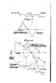
'Ihe direct current output of the balanced rectiiier circuit of the lsystem in Fig. 2, which comprises the discriminator, is depicted in Fig. 3. This figure shows the response characteristic of each of the rectiflers (dotted lines). It, also, shows the differential, or net output, response of the network (full line curve). The solid line curve of Fig. 3 is a representation of the variation of AFC bias with frequency of the signal energy impressed on the discriminator.
The operation of the AFC system is graphically represented in Fig. 4. The ordinates represent oscillator tank circuit capacity, and abscissae represent frequency. The latter may be taken either as the oscillator frequency or that of the I. F. signal carrier, as the two Vary together and differ by a constant amount equal to the radio frequency signal frequency. As the carrier is caused to traverse the I. F. transmission band, AFC bias generated by the differential rectifier network varies according to an S-shaped curve similar in form to dash line curve ai to d1. This bias, acting upon the oscillator frequency control tube and associated circuit, Varies the reactance reflected across the oscillator tank; which may be translated into terms of capacity, and the curve ai to di may be thought of as representing equivalent capacity thrown across the tank circuit by the control means. Let it be assumed that the operation of the system in Fig. 1 is being considered.
The total effective capacity is related to oscillator frequency by the nearly straight line az--da A portion of this total is physically present, not due to variations in the control tube, and variable, for example, only by manual means. This physical capacity is the difference between the total capacity and that thrown into the tank circuit by the control tube, and is represented by the solid curve, a2b2-c2-d2. This curve may be regarded as the control characteristic of the system.
If the tank capacity is continuously decreased, as by manual tuning, the oscillator frequency. and with it the I. F. carrier frequency, increases progressively until the point a2 is reached. Thereafter instability occurs; for an increase in frequency brings about a decrease in total capacity by means of the AFC action which further increases the frequency, and so on. What happens is that the I. F. carrier frequency jumps abruptly to as. Thereafter operation is stable until c2 is reached, at which point a second jump occurs to c3. Traversing the band in the opposite direction the jumps occur at d2 to d, and at b2 to b3. Throughout the segment bzcz stable operation occurs, and it is here that the desired control obtains. The ratio of the slope of D202 to that of the straight line azdz is the sensitivity of the control; this slope represents the ratio of a potential variation in the (uncontrolled) oscillator frequency to that which actually occurs when the control is operative.
Under optimum conditions the local oscillator frequency might be changed by as much as 200 k. c. for a 10 percent change in Gm of the-control tube. Using the type 76 tube as a control, this 10 percent change requires a change of grid bias of almost exactly 0.4 Volt. I have found, using only fair coils peaked l0 k. c, apart at an I. F. of 450 k. c., that 10 volts variation in AFC bias from peak to peak is readily obtainable without overloading. On this basis, a Vcontrol sensitivity of 500 to 1 is conservatively possible. If control of this sensitivity be maintained at all signal frequencies, the oscillator drift in short wave receivers will reduce to perhaps a hundred cycles, and even at three meters a superheterodyne would hold in tune as closely as the present broadcast receiver. Naturally, the problem is rather that of obtaining a fraction of this sensitivity without undue complications.
If the discriminator rectifier connections are reversed, the double kink in the control characteristic is inverted, and the two sides of the band become regions of stability, with instability over the center. Control obtains on the two edges of the band, and the I. F. carrier can be made to jump from one edge to the other, but will not remain in the center. This, also, occurs with the properly poled connections, if the signal is tuned in at the image position.
The present invention is not limited to the driving of the discriminator network as shown in Figs. 1 and 2. In Figs. 5 and 6 are shown two different modifications of this portion of the AFC system. Fig. 5 shows the tuned diode rectifiers of Fig. l supplied with signal energy from the I. F. amplifier through separate driver tubes 50, 5l. Thus, the I. F. energy is supplied to amplifier 50 for amplification and subsequent impression on the tuned circuit 23'; amplifier 5I functioning to amplify I. F. energy prior to impression on tuned circuit 24. The discriminator network of Fig. 5 differs from that shown in Fig. 1 in that the I. F. is not reduced to a lower value.
In Fig. 6 there is shown an arrangement wherein the plate circuit of the last I. F. amplifier includes in series the primaries feeding tuned circuits I3, 23' and 24. The I. F. amplier may use, in this case, a 58 type tube having a high Rp. This mode of connection can be used as common coupling effects do not interfere with the desired discrimination between higher and lower frequencies. Here, also, the I. F. is not reduced in value as in Figs. 1 and 2.
The local oscillator reactance changer unit may be varied in construction. Figs. 1 and 2 show two different forms of reactance changers. Figs. 7 to 10 inclusive illustrate further modified arrangements which may be employed for the desired function. In each figure it is to be understood that the tank circuit is that shown in either Fig. 1 or Fig. 2, and that the AFC bias may be derived from the discriminator networks shown in the latter systems, or those shown in Figs. 5 and 6.
In Fig. '7, the frequency control tube has its plate impedance vary with the bias upon the grid. When coupled to the tank circuit through condenser B0 (whose reactance is equal to Rp), the frequency change of the tank circuit, in kilocycles, for a given proportionate variation in Rp is independent of frequency, and is xed by the time constant of Rp and the tank tuning capacity. If the latter is made as small as possible, for example of the order of mmf., and the Rp of the tube is 10,000 ohms, a ten percent change in the latter will produce a frequency shift of 20 k. c.
The frequency control tube in Fig. 8 has its Rm 1 (mutual or trans-reslstance G- and Rp utilized in shunt combination to give a lower minimum value of variable tube resistance. The plate and grid are by-passed to ground, while the cathode is connected to the high alternating potential side of the tank circuit through condenser 60. A choke 6| connects the cathode to ground. If the tube Rm is thus utilized instead of the Rp its center value may be of the order of 1000 ohms, and the same percentage change in resistance will give a frequency shift of 200 k. c. The mean frequency should be large compared with the shift.
The arrangement in Fig, 10 is equivalent to that in Fig. 8. The cathode of the control tube is grounded, and the plate and grid, connected by the large blocking condenser 62, are connected to the high alternating potential side of the oscillator tank circuit through condenser 60. The Rm of the control tube is here utilized instead of the Rp.
The frequency control variant in Fig. 9 is intended to be a fixed reactance in series with a variable resistance of approximately equal magnitude, (as in Fig. 7); but in Fig. 9 the variable resistance is l/(Gm-i-Gp) instead of being Rp as in Fig. 7. Condenser 33 is large to place all the plate voltage on the grid; condenser 34 is small and is the fixed control reactance. The electrodes of the tube 30 are energized in substantially the same manner as shown in Fig. l. The high potential side of the oscillator tank circuit is here connected to the plate side of condenser 34 through condenser 33. Without entering into a detailed analysis of the characteristics it is pointed out that the output impedance is a function of the current amplification of the tube, and that the relation is an inverse one.
In Fig. ll is shown another AFC system modification; both the discriminator network and frequency control unit being modified and different from those disclosed up to this point. A portion of the I. F. carrier voltage at the input of the second detector is impressed upon the grid of tube T1. The receiver up to the second detector may be the same as that shown in Fig. 1. In the plate circuit of this tube the primaries P1 and Pz, of two similar I. F. transformers M4 and M5 are connected in parallel, and tuned to the exact center of the I. F. band; the resonance curve of this composite primary is broadened by the shunt resistance R1 of from 25,000 to 50,000 ohms. 'I'he secondaries S1 and S2 are tuned respectively at equal increments above and below the I. F. band mid-frequency.
Owing to the presence of R1 across the common primary the latter is essentially a constant voltage source, and, as there is no direct coupling between the two secondaries, the total effective coupling between the latter is negligible. 'I'he secondaries each operate into one of the anodes of double diode rectifier T2 having a common cathode which is ungrounded for direct current. This connection gives a direct current output which is the dierence between the rectified voltages from the two diodes. At a frequency near the resonance of S1 the output is negative, while at a symmetrical frequency near the resonance of S2 it is positive.
It is necessary to separate the resonant points of the two secondaries S1 and S2 by a minimum amount approximately equal to the I. F. midband frequency divided by the Q of the circuits. At 450 k. c., without considering losses introduced by the primary and by the diode load, a value of Q of 20D is about the highest that can be obtained in the usual size commercial I. F. coils. This corresponds to a minimum separation of 2.25 k. c. between the two secondary resonant points. After losses are accounted for, a separation of 4 or 5 k. c. would probably be excellent at this frequency. If a more selective discriminating device were necessary, recourse must be had to bulkier coils, or else a double heterodyne system used as in Fig. 1, the tube T1 operating as a converter with its output circuit tuned to a new and lower second I. P., 50 k. c. for example. The output from the balanced rectifier network is impressed upon the grid of the control tube T3. This tube, by means of any of several possible forms of reactive coupling circuit, causes the frequency of the oscillator to vary in accordance with the AFC bias, tending to return the I. F. carrier to the center of the I. band.
Iri the arrangement of Fig. 1l the coupling reactance is an inductance; this takes the form of a coil loosely coupled to the oscillatorA tank inductance. The excess inductive admittance of this coil is tuned out by a variable condenser across the control tube. The coupling becomes the familiar case of loosely coupled resonant circuits. This is the form of control circuit shown in Fig. l1. It is well known that if the tuned winding Sil is loosely coupled, as at Ms, to the tank circuit 8i of the local oscillator the frequency of the latter may be considerably changed by varying the tuning of the coil Sil, and, other things being equal, the amount of variation depends upon the damping of the circuit including coil Bti. For the present purpose the coil Sil is mistuned by a fixed amount, and the damping is varied by the variable shunt tube resistance. This method was experimented with in the 4 to 10 megacycle band, and it was found that a frequency variation of about one percent could be obtained over the whole band. It is pointed out that in this particular case one of the chief reasons for AFC would be to compensate for physical changes in the tank circuit due to thermal expansion, wai'page and the like. The variable condensers in circuits B, 8l are uni-controlled in order to keep the impedance reflected across the tank circuit a combination of a reactance and resistance of equal magnitude, or essentially so. This is the condition, and results in no change in load on the tank circuit when the rer sistance is changed (electronically), and likewise maximum change in frequency. If the reactance and resistance were very unequal, there would be a small change in frequency and a relatively large change in load. The uni-control is not intended to tulle the circuits to the same resonant point; the control circuit is tuned so that it was always reactive, by an amount equal in this case to the average Rp'of the tube.
In Fig. 12 there is shown an AFC system applied to a receiver wherein is used the repeated application of the heterodyne principle, with the controlled oscillator operating at a fixed frequency, lower than that of the first tunable oscillator. Without the frequency control feature, this is equivalent to a short wave converter connected to the input of a receiver intended for a lower frequency band; in the present case the second unit is provided with fixed input tuning. In the circuit a signal frequency of megacycles has been taken as a concrete example, and a nominal first I. F. of 2 megacyles has been assumed. It is further assumed that unwanted variations in the first oscillator may cause the actual I. F. to vary by +190 k. c. The coupling means between the output of the first converter and the input to the second is a band pass filter capable of passing 2(20 k. c. The second I. F. must be at least one half of this band width if image interference is to be avoided. The second I. F. of 175 k. c. is demodulated. It is also used for frequency control.
Thus, the discriminator and frequency control operate on the second local oscillator. Frequency drifts as high as k. c. in either direction from 2175 k. c. will be corrected by the AFC system. Specifically, there may be employed in the AFC system of Fig. 12, the discriminator network of Fig. 1l followed by the frequency control unit of Fig. 7. It is not believed necessary to include a specific disclosure of the last named particular AFC system to be employed in Fig. 12, as those skilled in the art will readily appreciate the manner of accomplishing this from the aforegoing detailed description.
This particular superheterodyne method is employed for the 50 megacycle signal range to provide a fixed nominal frequency for the oscillator to be controlled, it being simpler to control a nontunable oscillator than one that is tunable over a wide coverage band. A frequency in the neighborhood of 2 megacycles is shown for this second controllable oscillator as this seems to be optimum to obtain a wide AFC variation in k. c. A very low frequency is not good because a large percent change would be required, and a very high frequency is subject to a limitation from tube capacities.
While I have indicated and described several systems for carrying my invention into effect, it will be apparent to one skilled in the art that my invention is by no means limited to the particular organizations shown and described, but that many modifications may be made without departing from the scope of my invention, as set forth in the appended claims.
I claim:
l. A superheterodyne receiver comprising a frequency changer network including a local oscillator circuit, means for tuning the oscillator circuit over a wide frequency range, an intermediate frequency network, means for demodulating the intermediate frequency energy, a resonant discriminator network adapted to have intermediate frequency energy impressed thereon, said discriminator being constructed and arranged to produce a direct current voltage whose magnitude and polarity are solely dependent upon the frequency of said impressed energy, a variable reactance element connected in said local oscillator circuit as a supplemental tuning device and including an electron discharge tube, and means for impressing the direct current voltage produced by said discriminator upon a gain control electrode of said last named tube whereby the frequency of said local oscillator circuit may be increased or reduced to a predetermined frequency of said wide range selected by said tuning means, and a device, actuated by tuning adjustment of said tuning means, for automatically rendering said voltage impressing means ineffective.
2. A superheterodyne receiver comprising a frequency changer network including a local oscillator circuit, means for tuning the oscillator circuit over a wide frequency range, an intermediate frequency network, means for demodulating the intermediate frequency energy, a second frequency changer network for decreasing the frequency of the output of said intermediate network to a substantially lower intermediate frequency thereby to increase the rejection of adjacent channel signals, a discriminator network adapted to have said lower intermediate frequency energy impressed thereon and producing a direct current voltage whose magnitude is solely dependent upon the frequency of said impressed energy, a variable reactance element connected in said local oscillator circuit as a supplemental tuning device and including an electron discharge tube, and means for impressing the direct current voltage produced by said discriminator upon a gain control electrode of said last named tube whereby the frequency of said local oscillator circuit may be adjusted in a predetermined direction at any setting of said tuning means, and said discriminator network comprising a pair of rectifiers differentially connected, one rectifier being tuned to a frequency above said lower intermediate frequency, and the other rectifier being tuned to a frequency below the lower intermediate frequency.
3. A superheterodyne receiver comprising a frequency changer network including a local oscillator circuit, means for tuning the oscillator circuit over a wide frequency range, an inter- 'mediate frequency network, means for demodulating the intermediate frequency energy, a resonant discriminator network adapted to have'intermediate frequency energy impressed thereon and producing a direct current voltage whose magnitude and polarity are solely dependent upon the frequency of said impressed energy, a
yvariable reactance element connected in said local oscillator circuit as a supplemental tuning device and including an electron discharge tube, and means for impressing the direct current voltage produced by said discriminator upon a gain control electrode of said last named tube whereby the frequency of said local oscillator circuit may be adjusted in a predetermined direction at any setting of said tuning means, and a second frequency changer network for reducing the frequency value of said intermediate frequency energy prior to impression upon said discriminator network to an extent sufcient greatly to increase the selectivity of the latter thereby preventing the discriminator from being affected by adjacent channel signals.
4. In a superheterodyne receiver of the type including a signal input circuit, a local oscillator circuit, said oscillator circuit having main and auxiliary frequency determining elements, said auxiliary frequency determining element comprising anelectron discharge tube, a frequency changer, and an intermediate frequency network tuned to a carrier frequency Fi, a resonant circuit tuned to a frequency slightly below F1, means to rectify alternating voltage developed in the resonant circuit, a second resonant circuit tuned to a frequency slightly above Fi, means to rectify alternating voltage developed in the second resonant circuit, means to supply energy from the intermediate frequency network to said resonant circuits, and means responsive to the dierence between said rectified voltages to vary the gain of said frequency determining tube in such a sense as to cause the frequency of energy transmitted through the intermediate frequency network to approach more nearly to F1, a switch device for rendering the last means ineffective, and said main frequency determining element being constructed to actuate said switch device upon acljustment of the former.
5. In la superheterodyne receiver of the type including a signal input circuit, a local oscillator circuit, said oscillator circuit having main and auxiliary frequency determining elements, said auxiliary frequency determining element consisting solely of an electron discharge tube having an inductive impedance in its cathode circuit reactively coupled with the inductance of said oscillator circuit, a frequency changer having electrodes connected to said signal and oscillator circuits, and an intermediate frequency network tuned to a carrier frequency Fi coupled to the frequency changer. a resonant circuit tuned to a frequency slightly below F1, means to rectify alternating voltage developed in the resonant circuit, a second resonant circuit tuned to a frequency slightly above F1, means to rectify alternating voltage developed in the second resonant circuit, means to supply energy from the intermediate frequency network to said resonant circuits, the selectivity of the intermediate frequency network between the frequency changer and said resonant circuits being sufficiently high to prevent response of said rectifyng means to adjacent channel signals, and means responsive to the difference between said rectified voltages to vary the gain of said frequency determining tube in such a sense as to cause the frequency of energy transmitted through the intermediate frequency network to approach more nearly to Fi.
6. In a superheterodyne receiver of the type including a tunable signal circuit, and a tunable local oscillator network, means for simultaneously varying the tuning of said signal and local oscillator networks, an additional means in the local oscillator network for maintaining a constant frequency difference between the signal 4and local oscillator networks as the tuning means is varied, an intermediate frequency amplifier network, an auxiliary network comprising a pair of tuned circuits, each of said pair of tuned circuits being electrically associated with said intermediate frequency amplifier network, one of said pair of tuned circuits being tuned to a frequency diifering from the intermediate frequency by a value less than ve kilocycles, and the other of said pair of circuits being tuned to a frequency greater than said intermediate frequency by a similar value, a rectifier connected across each of said pair of tuned circuits, an auxiliary frequency control device for said local oscillator network, said device comprising an electron discharge tube having at least one electrode thereof reactively coupled to said oscillator network, and means responsive to a differential direct current flow of said rectifier circuits for adjusting the gain of said auxiliary control tube in a sense such that the energy impressed upon said pair of tuned circuits is made to approach in frequency said intermediate frequency value, a switch device for rendering the gain adjusting means ineffective, and said tuning means being arranged to actuate said switch device upon adjustment of the tuning means.
7. A method of receiving signals of a desired frequency which includes combining collected signals with locally produced oscillations of a dierent frequency to produce signals of a difference frequency, amplifying the last signals, demodulating the amplified signals of said difference frequency, reducing the amplified signals to a substantially lower frequency to increase the selectivity with respect to desired sigenergy, means for detecting the amplied heterodyne energy, means to increase the selectivity of the system relative to desired signals, said last means comprising a frequency reducing network for reducing the heterodyne energy to a substantially lower frequency, and means, re-
sponsive to Ia departure of the reduced heterodyne energy from said lower frequency value, for automatically adjusting the frequency of said oscillator in a sense to maintain said reduced heterodyne energy at the lower frequency value.
CHARLES TRAVIS.
Priority Applications (4)
| Application Number | Priority Date | Filing Date | Title |
|---|---|---|---|
| US4793A US2294100A (en) | 1935-02-04 | 1935-02-04 | Automatic oscillator frequency control system |
| FR801070D FR801070A (en) | 1935-02-04 | 1936-01-22 | Improvements to automatic oscillator frequency control systems |
| GB3383/36A GB471738A (en) | 1935-02-04 | 1936-02-04 | Improvements in and relating to wireless and like receivers |
| US115562A US2153779A (en) | 1935-02-04 | 1936-12-12 | Automatic oscillator frequency control system |
Applications Claiming Priority (2)
| Application Number | Priority Date | Filing Date | Title |
|---|---|---|---|
| US4793A US2294100A (en) | 1935-02-04 | 1935-02-04 | Automatic oscillator frequency control system |
| US115562A US2153779A (en) | 1935-02-04 | 1936-12-12 | Automatic oscillator frequency control system |
Publications (1)
| Publication Number | Publication Date |
|---|---|
| US2294100A true US2294100A (en) | 1942-08-25 |
Family
ID=40691373
Family Applications (1)
| Application Number | Title | Priority Date | Filing Date |
|---|---|---|---|
| US4793A Expired - Lifetime US2294100A (en) | 1935-02-04 | 1935-02-04 | Automatic oscillator frequency control system |
Country Status (1)
| Country | Link |
|---|---|
| US (1) | US2294100A (en) |
Cited By (9)
| Publication number | Priority date | Publication date | Assignee | Title |
|---|---|---|---|---|
| US2422082A (en) * | 1943-03-03 | 1947-06-10 | Rca Corp | Reactance control circuit |
| US2422257A (en) * | 1935-04-26 | 1947-06-17 | Radio Patents Corp | Electronic reactance circuits |
| US2467345A (en) * | 1935-05-03 | 1949-04-12 | Rca Corp | Automatic frequency control system |
| US2477076A (en) * | 1945-10-12 | 1949-07-26 | Bell Telephone Labor Inc | Frequency control system |
| US2560312A (en) * | 1947-10-03 | 1951-07-10 | Philco Corp | Tuning aid for radio receivers |
| US2676256A (en) * | 1946-03-04 | 1954-04-20 | Gen Electric | Automatic frequency control system |
| US2931900A (en) * | 1955-01-31 | 1960-04-05 | David M Goodman | Electrical testing |
| US2979610A (en) * | 1957-09-24 | 1961-04-11 | Trt Telecom Radio Electr | Single side-band receiver for reception of single side-band signals by means of a carrier-wave frequency |
| US4107615A (en) * | 1975-08-28 | 1978-08-15 | U.S. Philips Corporation | Receiver including an automatic tuning correction suppression circuit coupled to the tuning member |
-
1935
- 1935-02-04 US US4793A patent/US2294100A/en not_active Expired - Lifetime
Cited By (9)
| Publication number | Priority date | Publication date | Assignee | Title |
|---|---|---|---|---|
| US2422257A (en) * | 1935-04-26 | 1947-06-17 | Radio Patents Corp | Electronic reactance circuits |
| US2467345A (en) * | 1935-05-03 | 1949-04-12 | Rca Corp | Automatic frequency control system |
| US2422082A (en) * | 1943-03-03 | 1947-06-10 | Rca Corp | Reactance control circuit |
| US2477076A (en) * | 1945-10-12 | 1949-07-26 | Bell Telephone Labor Inc | Frequency control system |
| US2676256A (en) * | 1946-03-04 | 1954-04-20 | Gen Electric | Automatic frequency control system |
| US2560312A (en) * | 1947-10-03 | 1951-07-10 | Philco Corp | Tuning aid for radio receivers |
| US2931900A (en) * | 1955-01-31 | 1960-04-05 | David M Goodman | Electrical testing |
| US2979610A (en) * | 1957-09-24 | 1961-04-11 | Trt Telecom Radio Electr | Single side-band receiver for reception of single side-band signals by means of a carrier-wave frequency |
| US4107615A (en) * | 1975-08-28 | 1978-08-15 | U.S. Philips Corporation | Receiver including an automatic tuning correction suppression circuit coupled to the tuning member |
Similar Documents
| Publication | Publication Date | Title |
|---|---|---|
| US2286378A (en) | Frequency modulated wave detector | |
| US2240428A (en) | Electrical circuits | |
| US2294100A (en) | Automatic oscillator frequency control system | |
| US2357984A (en) | Automatic frequency control system | |
| US2296100A (en) | Frequency modulated wave receiver | |
| US2379688A (en) | Frequency modulation receiver circuits | |
| US2519890A (en) | Angle modulated wave receiver | |
| US2496818A (en) | Angle modulation detector | |
| US2233778A (en) | Automatic frequency control circuit | |
| US2250519A (en) | Automatic tuning system | |
| US2273110A (en) | Frequency modulated wave receiver | |
| US2540532A (en) | Superheterodyne receiver with compensation for mistuning caused by automatic volume control | |
| US2528182A (en) | Frequency discriminator network | |
| US2341240A (en) | Frequency discriminator network | |
| US2033986A (en) | Frequency converter | |
| US2121735A (en) | Automatic frequency control circuit | |
| US2153779A (en) | Automatic oscillator frequency control system | |
| US2177713A (en) | Frequency-selective network | |
| US2144935A (en) | Automatic volume control circuits | |
| US2128661A (en) | Automatic frequency control system | |
| US2374265A (en) | Tuning of radio receivers | |
| US2167400A (en) | Variable selectivity radio receiver | |
| US2120998A (en) | Coupled circuits | |
| US2488606A (en) | Frequency modulation receiver | |
| US2172456A (en) | Automatic frequency control circuit |