US2271663A - Throttle actuating device - Google Patents
Throttle actuating device Download PDFInfo
- Publication number
- US2271663A US2271663A US355586A US35558640A US2271663A US 2271663 A US2271663 A US 2271663A US 355586 A US355586 A US 355586A US 35558640 A US35558640 A US 35558640A US 2271663 A US2271663 A US 2271663A
- Authority
- US
- United States
- Prior art keywords
- pusher
- guide
- accelerator pedal
- pedal
- figures
- Prior art date
- Legal status (The legal status is an assumption and is not a legal conclusion. Google has not performed a legal analysis and makes no representation as to the accuracy of the status listed.)
- Expired - Lifetime
Links
Images
Classifications
-
- G—PHYSICS
- G05—CONTROLLING; REGULATING
- G05G—CONTROL DEVICES OR SYSTEMS INSOFAR AS CHARACTERISED BY MECHANICAL FEATURES ONLY
- G05G1/00—Controlling members, e.g. knobs or handles; Assemblies or arrangements thereof; Indicating position of controlling members
- G05G1/30—Controlling members actuated by foot
-
- Y—GENERAL TAGGING OF NEW TECHNOLOGICAL DEVELOPMENTS; GENERAL TAGGING OF CROSS-SECTIONAL TECHNOLOGIES SPANNING OVER SEVERAL SECTIONS OF THE IPC; TECHNICAL SUBJECTS COVERED BY FORMER USPC CROSS-REFERENCE ART COLLECTIONS [XRACs] AND DIGESTS
- Y10—TECHNICAL SUBJECTS COVERED BY FORMER USPC
- Y10T—TECHNICAL SUBJECTS COVERED BY FORMER US CLASSIFICATION
- Y10T74/00—Machine element or mechanism
- Y10T74/20—Control lever and linkage systems
- Y10T74/20528—Foot operated
- Y10T74/20534—Accelerator
Definitions
- pusher member D operatively interconnecting several improvements have been made to provide a device which can be used in combination with the throttle of an automobile and, in particular, "in combination with the accelerator pedals, such as are now used in the modern vehicle.
- This invention provides a still further improvement which will more fully appear from the fol--.
- Figures 1 and 3 are longitudinal side-views of two different embodiments of this device mounted on an accelerator pedal.
- Figures '2 and 4 are plan-views of Figures 1 and 2. i
- FIG. 5 is a schematical diagrammatical view of one embodiment.
- Figure 6 is a longitudinal side-view of the device using the method of Figure 5.
- Figure '7 is a cross-sectional view of another embodiment similar to that illustrated on Figure 1.
- Figures 8 and 8a represent a plan-view with parts broken out'of a double-pulley.
- Figure 9 represents cross-sectional view of another embodiment of the device and the accelerator pedal with parts broken out.
- the pedal may be of any shape or size. It may be round or as illustrated on balls, clips, or by glue or cement, or it may be.
- a pusher-member D may consist, for instance, of a member and flanges "bent or extending downwards, on which flanges are mounted preferably two axles 52, i. e. preferably at least one axle on each flange, on which axle or axles rollers RI are freely rotatable, as illustrated in Figures 1, 2, 3 and 4.
- axles 52 i. e. preferably at least one axle on each flange, on which axle or axles rollers RI are freely rotatable, as illustrated in Figures 1, 2, 3 and 4.
- members can be employed, themselves forming axles.
- FIG. 10 is a plan-view of Figure 9.
- the pushermember D also may be provided, if desired, with guide-means R3, preferably rollers, to prevent the downward pressure of the accelerator pedal produced by the weight of the foot, thus permitting the foot to rest without'any pressure on the pusher-member.
- a flexible'connection F is attached byone end to the. support Bl affixed rigidly to the pedal P, and by passing through the roller R4 (or guidemeans) and roller R5, it. operates pusher-member D.
- Such arrangement will pull the pedal P downwards for a distance K, Figure 1, as soon as pusher-member D is pushed forwards for the same distance X.
- the 'axis 51 of the double-pulley may be amxed perpendicular to the floor, as shown on Figures 1 and 2, or horizontal in respect thereto, Figures 3 and 4, or at any desirable angle.
- a system of movable train-pulleys 58 and BI may be used,-
- the flexible connection fl is afiixed to a support 59 and after passing through the pulley 58 is then affixed to the frame 63.
- the flexible connection f2 is affixed to a support 62 and after passing through the pulley (or roller) 6
- Pusher-member D when pushed to and fro, actuates the throttle.
- the pusher-member D may be mounted, as illustrated on Figures 7, 9, l0, and 11, or Figures 1, 2, 3, 4 and 6. If desired, D may also roll on a guide-means G1 especially provided therefor (preferably on both sides of thepedal) Pusher-member D may have arresting means 86, on which a sponge-rubber 61 or other friction-augmenting material is afiixed.
- Roller 68, 69 or 10 mounted on their respective axles rigid with pusher-member D, may roll or slide in a guiding slot ll provided in a frame 12.
- the axis of the roller 69, Figures 10 and 11, may be provided with an element 13 to which the flexible connection F or ii, or ii, may be aflixed.
- FIG. 12 to 18 Another embodiment is shown on Figures 12 to 18, wherein the pusher-member D is not mounted on the pedal P but on a special guide-member l4 rigid in respect to the floor 15.
- D2 and guidemember 14 may be flat or of any suitable curved surface.
- the guide-member 14 may be provided with a slot 16 through which the pusher-member D is attached to the flexible connection, and in which slot the pusher-member is guided accordingly when pushed to and fro.
- the floor I5 and, eventually, the outer part 14. of the guide member 14 may be covered with friction-augmenting (or diminishing) means 11'.
- Pusher-member 18, Figures and 16 may be provided with roller 19 (or rollers) .which roll on support 14, and with a guiding-element 88, passing through the slot 16, and to which element 80 the flexible connection 8
- the pusher-member 82 may be covered by vibration-diminishing means and also by friction-augmenting means 'I
- the pusher 82 may have a fixation-means in its center, to which the flexible connection may be attached.
- the width 81 Figure l8 may be equal to the width 88 of the pusher 82, or may be much smaller than 88.
- the contact surfaces between the pusher 82 and the flanges 85-85 may be polished and/or oiled in order to offer less friction.
- the flexible connection may be a cord, a wire, a chain, a belt, a caterpillar-chain. or the like.
- the fixation means through which the flexible connection e or 01 are affixed to the pedal may be of any shape or form.
- Device D and its component parts may be made of metal, wood, glass or any suitable plastic, or'a suitable combination thereof. It desired, this device and its component parts may be cast, stamped or pressed out.
- first guide-means rigidly ailixed in respect to the floor
- second guide-means rigidly afllxed in respect to the said accelerator pedal
- first flexible connecting means consisting of a first flexible connection, one end of which is amxed to the said accelerator pedal and the other end rigidly afllxed to the periphery of" one guide-means which is guided on the said first guide-means preferably through the intermediary attached to the-said pedal and the other end to v of a roller attached to a pusher-member which is guided on the said first guide means preferably contacting the said second guide means through the intermediary of at least one roller, whereby when said pusher-member is pushed to and fro contacting the second guide-means, said first and said second flexible connecting means are each moved in proportion to the diameters of their respective pulleys, the diameter of the said second pulley being sufiiciently larger than the diameter of the said first
- a device as set forth in claim 2 wherein instead of one group of pulleys composed pf the said first and said second pulleys, more than one of such groups is employed operatively interconnected one with the other by suitable flexible means of the character referred to.
- a first guide means rigidly afllxed in respect to the floor
- a second guide means rigidly aflixed in respect to the said accelerator pedal
- a pusher-member provided on the said accelerator pedal to displace itself substantially.
- a pusher-member provided on the said accelerator pedal, said pusher-member provided with guides capable of contacting simultaneously the said first and second guide-means, a flexible connection operatively interconnected with the said accelerator pedal and the said pusher-member, whereby when the said pusher-member is pushed to and fro, the said accelerator pedal is actuated.
- a flexible connecting means consisting of two flexible connections, the first of said flexible connections having its one end aflixed to the said pedal and its other end to the frame of a pulley, said first flexible connection passing on its way through a guide rigidly affixed in respect to the floor, said second flexible connection being affixed by its one end to a member rigid with the floor and by its other end attached to a pushermember provided on the said accelerator pedal, which is guidedon the said first and second guide means preferably through the intermediary of at least one roller, said second flexible connection passing on its way through a guide afiixed rigidly in respect to the floor, whereby when the said pusher-member is pushed to and fro ble connection, one end of said flexible connecting means attached to the said pedal and the other end to the said pusher,
Description
Feb. 3, 1942. I G. A. RUBISSOW 2,271,663
THROTTLE ACTUATING DEVICE Filed Sept. 6, 1940 2 Sheets-Sheet 1 T13? El 0, P 54 as M NVENTOR. Q;
Feb. 3, 1942. e. A. RUBISSOW I ,6
THROTTLE ACTUATING DEVICE Filed Sept. 6, 1940 2 Shets-Sheet 2 0 If m,
15 INVENTOR.
Patented Feb. 3,1942
UNITED STATES PATENT OFFICE 'rnaor'rm AOTUA'I'ING navrcs George A. Bublssow, New York, N. Y. Application September a, 1940, Serial No. 355,580 10'OlaIml. o1. 11-513) pusher member D, operatively interconnecting several improvements have been made to provide a device which can be used in combination with the throttle of an automobile and, in particular, "in combination with the accelerator pedals, such as are now used in the modern vehicle.
This invention provides a still further improvement which will more fully appear from the fol--.
lowing description when the same is read in connection with the accompanying drawings and the appended claims. It is to be expressly understood, however, that the drawings are for pur-- poses of schematical illustration only and are not intended as a definition as to the design or to the limits of the several aspects of this invention.
All figures represent diflerent aspects of this invention in simplified and diagrammatical form of illustration. In the drawings wherein like reference characters refer to like parts throughout the several views:
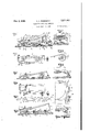
Figures 1 and 3 are longitudinal side-views of two different embodiments of this device mounted on an accelerator pedal.
Figures '2 and 4 are plan-views of Figures 1 and 2. i
I Figure 5 is a schematical diagrammatical view of one embodiment.
Figure 6 is a longitudinal side-view of the device using the method of Figure 5.
Figure '7 is a cross-sectional view of another embodiment similar to that illustrated on Figure 1.
Figures 8 and 8a represent a plan-view with parts broken out'of a double-pulley.
Figure 9 represents cross-sectional view of another embodiment of the device and the accelerator pedal with parts broken out.
the accelerator pedal with the guide-means GI or GI and G2. The pedal may be of any shape or size. It may be round or as illustrated on balls, clips, or by glue or cement, or it may be.
one piece with the pedalor be the pedal itself, having a suitable surface which can be considered as serving for or substituting for the said guidemeans GI. The shape of the guide-means GI may4be a straight line as shown on Figures 1, 2, 3 and t A pusher-member D may consist, for instance, of a member and flanges "bent or extending downwards, on which flanges are mounted preferably two axles 52, i. e. preferably at least one axle on each flange, on which axle or axles rollers RI are freely rotatable, as illustrated in Figures 1, 2, 3 and 4. Instead of flanges, members can be employed, themselves forming axles.
Another guide-means G2 is mounted rigidly in v respect to the floor and has a contour which is Figure 10 is a plan-view of Figure 9.
suitable for rolling or sliding thereon the aforementioned pusher-member D. The pushermember D also may be provided, if desired, with guide-means R3, preferably rollers, to prevent the downward pressure of the accelerator pedal produced by the weight of the foot, thus permitting the foot to rest without'any pressure on the pusher-member.
A flexible'connection F is attached byone end to the. support Bl affixed rigidly to the pedal P, and by passing through the roller R4 (or guidemeans) and roller R5, it. operates pusher-member D. Such arrangement will pull the pedal P downwards for a distance K, Figure 1, as soon as pusher-member D is pushed forwards for the same distance X.
In the case that the pusher-member D takes the positionDI with its longitudinal displacement Y be greater than the vertical downward One embodiment of this invention consists in means G2 rigid with respect to the floor and a displacement X of the pedal, then a double pulley 55 and 56 is used, as shown on Figures 1, 2, 3, .4, and 8. Instead of being in one piece the flexible connection F, is made of two pieces e attached to the pedal P and to the pulley 55, and f attached to the larger pulley 56 and to the pushermember D. The radius R of 56 is greater than the radius r of 55. 58 and 55 are rigid in respect to each other and both rotate on a common axis 51.
The 'axis 51 of the double-pulley may be amxed perpendicular to the floor, as shown on Figures 1 and 2, or horizontal in respect thereto, Figures 3 and 4, or at any desirable angle. Instead of a fixed axis 51 and double-pulley 55-58, a system of movable train-pulleys 58 and BI may be used,-
when mounted on frames 88 and 83. The flexible connection e1 Figures 5 and 6 passing through roller (or guide-means) 65, is afflxed to the frame 60. The flexible connection fl is afiixed to a support 59 and after passing through the pulley 58 is then affixed to the frame 63. The flexible connection f2 is affixed to a support 62 and after passing through the pulley (or roller) 6|, passes through a roller (or guide-means) 64 and is thereafter aflixed to the pusher-member D. When the pulley 58 makes a displacement of X and takes the position 581, Figure 5, the pulley 6| makes a displacement of 2.X and takes the position 6h.
Such devices as shown on Figures 1, 2, 3, 4, 5, 6 and 8 offer the desired differentiation of the force necessary to actuate the accelerator pedal. Thus, the pusher-member, when pushed to and fro, actuates the throttle. The pusher-member D may be mounted, as illustrated on Figures 7, 9, l0, and 11, or Figures 1, 2, 3, 4 and 6. If desired, D may also roll on a guide-means G1 especially provided therefor (preferably on both sides of thepedal) Pusher-member D may have arresting means 86, on which a sponge-rubber 61 or other friction-augmenting material is afiixed.
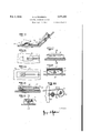
Another embodiment is shown on Figures 12 to 18, wherein the pusher-member D is not mounted on the pedal P but on a special guide-member l4 rigid in respect to the floor 15. D2 and guidemember 14 may be flat or of any suitable curved surface. The guide-member 14 may be provided with a slot 16 through which the pusher-member D is attached to the flexible connection, and in which slot the pusher-member is guided accordingly when pushed to and fro. The floor I5 and, eventually, the outer part 14. of the guide member 14 may be covered with friction-augmenting (or diminishing) means 11'. Pusher-member 18, Figures and 16, may be provided with roller 19 (or rollers) .which roll on support 14, and with a guiding-element 88, passing through the slot 16, and to which element 80 the flexible connection 8| is attached.
The pusher-member 82, Figures 17 and 18, may be covered by vibration-diminishing means and also by friction-augmenting means 'I|.' It may also be provided with two downward-extending guiding- flanges 84, 84, which slide easily on the flanges of the guide-means 85, 88, especially provided therefor.
The pusher 82 may have a fixation-means in its center, to which the flexible connection may be attached. The width 81 Figure l8 may be equal to the width 88 of the pusher 82, or may be much smaller than 88. The contact surfaces between the pusher 82 and the flanges 85-85 may be polished and/or oiled in order to offer less friction. The flexible connection may be a cord, a wire, a chain, a belt, a caterpillar-chain. or the like.
Instead of placing the pulley or the doublepulley below the throttle as illustrated in Figures 2 and 4, it can be provided at one side of the throttle or in front of as shown in Figure 8a, wherein the pulleys operate exactly in the'same manner as shown in Figures 2 and 8, but are situated in the rear of the accelerator pedal. Thus they do not occupy any space below the pedal. The fixation means through which the flexible connection e or 01 are affixed to the pedal, may be of any shape or form.
Device D and its component parts, may be made of metal, wood, glass or any suitable plastic, or'a suitable combination thereof. It desired, this device and its component parts may be cast, stamped or pressed out.
Having now particularly described and ascertained the nature of the said invention and in what manner the same is to be performed, I declare that what I claim is:
1. In combination with the accelerator pedal of a vehicle. a guide-means rigidly affixed in respect to the said accelerator pedal, 9. pushermember provided on the said accelerator pedal, 8. flexible connection operatively interconnected with the said accelerator pedal and the said pusher-member, whereby when the said pushermember is pushed to and fro, the said accelerator pedal is actuated.
2. In combination with the accelerator, pedal of a vehicle, a first guide-means rigidly afllxed in respect to the floor, a second guide-means rigidly affixed in respect to the said accelerator pedal, a flexible connecting means consisting of ible connection one end of which is rigidly affixed to the periphery of a second pulley, said second pulleyrigid and co-axial with the said first pulley, the other end of said other flexible connecting means passing through one guidemeans, preferably a roller, attached to a pushermember which is guided on the said first guidemeans preferably through the intermediary of at least one roller, and when said pusher-member is pushed to and fro contacting the second guide-means, said first and second flexible connections are each moved in proportion to the diameters of their respective pulleys, whereby the accelerator pedal is operated.
3. In combination with the accelerator pedal of a vehicle, a first guide-means rigidly ailixed in respect to the floor, a second guide-means rigidly afllxed in respect to the said accelerator pedal, 8. first flexible connecting means consisting of a first flexible connection, one end of which is amxed to the said accelerator pedal and the other end rigidly afllxed to the periphery of" one guide-means which is guided on the said first guide-means preferably through the intermediary attached to the-said pedal and the other end to v of a roller attached to a pusher-member which is guided on the said first guide means preferably contacting the said second guide means through the intermediary of at least one roller, whereby when said pusher-member is pushed to and fro contacting the second guide-means, said first and said second flexible connecting means are each moved in proportion to the diameters of their respective pulleys, the diameter of the said second pulley being sufiiciently larger than the diameter of the said first pulley, and the accelerator pedal is accordingly actuated.
4. In combination with the accelerator pedal of a vehicle, a first guide-means rigidly ailixed in respect to the floor, a second guide-means rigidly aifixed in respect to the said accelerator pedal, a flexible connecting means one end of which is attached to the said accelerator pedal, the said flexible connection passing through at least one pulley placed in the vicinity of the said end of the said flexible connecting means and at least through one other pulley placed in the vicinity of the other end of the said flexible connecting means, the said other end of the said flexible connecting means being aflixed to a pusher-member provided preferably with roller contacting the said first guide-means, whereby when pushing to and fro the said pusher-member, the accelerator pedal is operated accordingly.
5. A device as set forth in claim 2 wherein instead of one group of pulleys composed pf the said first and said second pulleys, more than one of such groups is employed operatively interconnected one with the other by suitable flexible means of the character referred to.
6. In combination with the accelerator pedal of a vehicle, a first guide means rigidly afllxed in respect to the floor, a second guide means rigidly aflixed in respect to the said accelerator pedal, a pusher-member provided on the said accelerator pedal to displace itself substantially.
along it and provided with guides operatively interconnecting the said first and second guide means, at least one flexible connecting means operatively interconnectingthe said pedal and the said pusher, one end of the said flexible the said pusher, said two flexible connections being operatively interconnected through at least connecting means attached to the said pedal and the other end to the said pusher, atleast one guide preferably a roller and at least one pulley provided for, the said flexible connecting means.
'I. In combination with the accelerator pedal of a vehicle, at least two guides rigidly affixed in respect to the floor, a to and fro sliding pusher member mounted on. a support afnxed rigidly in respect to the said floor, a flexible connecting means composed of at least two flexible connections, one end of said flexible connecting means two pulleys provided therefor, wherebywhen the said pusher is pushed to and fro the throttle of the said vehicle is accordingly actuated.
8. In combination with an accelerator pedal of a vehicle, a first guide .means rigidly afllxed to the said accelerator pedal, a second guide means rigidly affixed in respect to the floor,,
a pusher-member provided on the said accelerator pedal, said pusher-member provided with guides capable of contacting simultaneously the said first and second guide-means, a flexible connection operatively interconnected with the said accelerator pedal and the said pusher-member, whereby when the said pusher-member is pushed to and fro, the said accelerator pedal is actuated.
9. In combination with the accelerator pedal of a vehicle, a first guide-means rigidly aifixed in respect to the floor, a second guide-means rigidly affixed in respect to the said acceleratorpedal', a flexible connecting means consisting of two flexible connections, the first of said flexible connections having its one end aflixed to the said pedal and its other end to the frame of a pulley, said first flexible connection passing on its way through a guide rigidly affixed in respect to the floor, said second flexible connection being affixed by its one end to a member rigid with the floor and by its other end attached to a pushermember provided on the said accelerator pedal, which is guidedon the said first and second guide means preferably through the intermediary of at least one roller, said second flexible connection passing on its way through a guide afiixed rigidly in respect to the floor, whereby when the said pusher-member is pushed to and fro ble connection, one end of said flexible connecting means attached to the said pedal and the other end to the said pusher, said flexible connection being operatively interconnected through at least the said two guide means, whereby when the said pusher is pushed to and fro the throttle of the said vehicle is accordingly actuated.
GEORGE A. nnnrssow:
Priority Applications (1)
| Application Number | Priority Date | Filing Date | Title |
|---|---|---|---|
| US355586A US2271663A (en) | 1940-09-06 | 1940-09-06 | Throttle actuating device |
Applications Claiming Priority (1)
| Application Number | Priority Date | Filing Date | Title |
|---|---|---|---|
| US355586A US2271663A (en) | 1940-09-06 | 1940-09-06 | Throttle actuating device |
Publications (1)
| Publication Number | Publication Date |
|---|---|
| US2271663A true US2271663A (en) | 1942-02-03 |
Family
ID=23397996
Family Applications (1)
| Application Number | Title | Priority Date | Filing Date |
|---|---|---|---|
| US355586A Expired - Lifetime US2271663A (en) | 1940-09-06 | 1940-09-06 | Throttle actuating device |
Country Status (1)
| Country | Link |
|---|---|
| US (1) | US2271663A (en) |
Cited By (3)
| Publication number | Priority date | Publication date | Assignee | Title |
|---|---|---|---|---|
| US2566638A (en) * | 1948-05-25 | 1951-09-04 | Casper A Brictson | Wear pad |
| US4320673A (en) * | 1978-12-22 | 1982-03-23 | Dr. Ing. H.C.F. Porsche Aktiengesellschaft | Control device for an automatic drive of an automobile |
| US20050016322A1 (en) * | 2001-12-19 | 2005-01-27 | Olivier Bouteville | Ford-feedback mechanism |
-
1940
- 1940-09-06 US US355586A patent/US2271663A/en not_active Expired - Lifetime
Cited By (4)
| Publication number | Priority date | Publication date | Assignee | Title |
|---|---|---|---|---|
| US2566638A (en) * | 1948-05-25 | 1951-09-04 | Casper A Brictson | Wear pad |
| US4320673A (en) * | 1978-12-22 | 1982-03-23 | Dr. Ing. H.C.F. Porsche Aktiengesellschaft | Control device for an automatic drive of an automobile |
| US20050016322A1 (en) * | 2001-12-19 | 2005-01-27 | Olivier Bouteville | Ford-feedback mechanism |
| US7318361B2 (en) * | 2001-12-19 | 2008-01-15 | Siemens Vdo Automotive | Thrust return mechanism |
Similar Documents
| Publication | Publication Date | Title |
|---|---|---|
| US2271663A (en) | Throttle actuating device | |
| MX172009B (en) | SAFETY SLIDING WITH WHEELS FOR VEHICLE SEATS | |
| US2195349A (en) | Seat slide structure | |
| US2967741A (en) | Machine tools, particularly grinding machines | |
| US2545212A (en) | Skeining machine | |
| GB779532A (en) | Improvements in slides for vehicle seats and the like | |
| US3729827A (en) | Carriage for drawing devices | |
| GB374613A (en) | Automatic belt shifting mechanism for apparatus for grinding or trueing leather covered or other rollers used in the textile or other trades | |
| US1748539A (en) | Press | |
| GB745253A (en) | Improvements in or relating to a mechanism for the dual control of a vehicle | |
| US1461758A (en) | Cable-measuring device | |
| KR830002830Y1 (en) | Front and rear movement of passenger car seat | |
| GB661612A (en) | Improvements in seats for motor and other vehicles | |
| US2235850A (en) | Throttle actuating device | |
| GB308862A (en) | Improvements relating to seats for motor vehicles | |
| US416923A (en) | Thomas m | |
| ES328680A1 (en) | Improvements in wagon floors for transport of vehicles. (Machine-translation by Google Translate, not legally binding) | |
| US1765234A (en) | Leather-sorting machine | |
| GB1188498A (en) | Apparatus for Projecting Balls | |
| US1118048A (en) | Store-service apparatus. | |
| GR3661B (en) | ADJUSTABLE LEVER SYSTEM FOR OPERATING THE WHEELS BY VEHICLES MOVING ON RAILWAYS. | |
| KR860002455Y1 (en) | Larabike | |
| ES443244A1 (en) | Draw and buffing gear | |
| ES49355U (en) | Guide device for miniature vehicles, toy (Machine-translation by Google Translate, not legally binding) | |
| FR2278616A1 (en) | Spool carrier with adjustable driving brace - has two pivoting centring pieces inside hollow shaft and brake |