US2217618A - Hydraulically operated grinding machine - Google Patents
Hydraulically operated grinding machine Download PDFInfo
- Publication number
- US2217618A US2217618A US270594A US27059439A US2217618A US 2217618 A US2217618 A US 2217618A US 270594 A US270594 A US 270594A US 27059439 A US27059439 A US 27059439A US 2217618 A US2217618 A US 2217618A
- Authority
- US
- United States
- Prior art keywords
- valve
- fluid
- wheel
- cylinder
- pressure
- Prior art date
- Legal status (The legal status is an assumption and is not a legal conclusion. Google has not performed a legal analysis and makes no representation as to the accuracy of the status listed.)
- Expired - Lifetime
Links
- 239000012530 fluid Substances 0.000 description 78
- 230000007246 mechanism Effects 0.000 description 31
- 230000006835 compression Effects 0.000 description 3
- 238000007906 compression Methods 0.000 description 3
- 239000002023 wood Substances 0.000 description 3
- 238000010276 construction Methods 0.000 description 2
- 230000013011 mating Effects 0.000 description 2
- 230000007935 neutral effect Effects 0.000 description 2
- 241000282472 Canis lupus familiaris Species 0.000 description 1
- 230000000694 effects Effects 0.000 description 1
- 238000009429 electrical wiring Methods 0.000 description 1
- 230000002427 irreversible effect Effects 0.000 description 1
- PSGAAPLEWMOORI-PEINSRQWSA-N medroxyprogesterone acetate Chemical compound C([C@@]12C)CC(=O)C=C1[C@@H](C)C[C@@H]1[C@@H]2CC[C@]2(C)[C@@](OC(C)=O)(C(C)=O)CC[C@H]21 PSGAAPLEWMOORI-PEINSRQWSA-N 0.000 description 1
- 239000002184 metal Substances 0.000 description 1
- 230000002441 reversible effect Effects 0.000 description 1
- 239000011435 rock Substances 0.000 description 1
Images


Classifications
-
- B—PERFORMING OPERATIONS; TRANSPORTING
- B24—GRINDING; POLISHING
- B24B—MACHINES, DEVICES, OR PROCESSES FOR GRINDING OR POLISHING; DRESSING OR CONDITIONING OF ABRADING SURFACES; FEEDING OF GRINDING, POLISHING, OR LAPPING AGENTS
- B24B47/00—Drives or gearings; Equipment therefor
- B24B47/02—Drives or gearings; Equipment therefor for performing a reciprocating movement of carriages or work- tables
- B24B47/06—Drives or gearings; Equipment therefor for performing a reciprocating movement of carriages or work- tables by liquid or gas pressure only
Definitions
- One object of the invention is to provide a simple and thoroughly practical grinding machine table traversing mechanism. Another object of the invention is to provide a manually controlled table traverse mechanism bywhich the table may be traversed easily without undue exertion on the part of the operator. 'Another object of the invention is to provide a manually controlled hydraulically operated table reversing mechanism. Another object of the invention is to provide a manually controlled hydraulically actuated table traversing -mechanism in which the speed of movement of the controlmember, such as the rotation of a hand wheel, serves to control the rate of traversing movement of the 2 table. Another object of the invention is to provide a fluid pressure operated manually permitted table traverse mechanism.
- a further object of the invention is to provide a low pressure hydraulic traversing mechanism for the table combined 25 with a manually operable mechanism including a .worm and worm gear mechanism to govern and control said hydraulic movement.
- Fig. 1 is a front elevation of a cylindrical grinding machine embodying this invention
- Fig. 2 is a diagrammatic illustration, of the hydraulic system combined with an electrical wiring diagramj 1
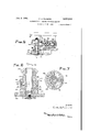
- Fig. 3 is a fragmentary front elevation, on an enlarged scale, of the manually operable traverse mechanism, having the front cover-removed;
- Fig. 4 is a cross sectional view' taken. approximately-ontheline [-1 of Fig. 3; -Fig. i5' is a fragmentary sectional view taken 50 approximately onthe'line 5-5 of Fig. 3;
- Fig. 6 is a fragmentary sectional view, on an enlarged scale, takenapproximately on the line 6-6 of Fig. .5;
- FIG. 7 is a cross sectional view taken approxi- 55 mately on the linel-l of Fig. 6. i
- the invention relates tolgrinding machines
- a cylindrical grinding machine has been illustrated in the drawings comprising a base I0 having a transversely movable wheel slide II which is movable transversely on the usual V-way and flat way (not shown).
- a rotatable grinding 6 wheel i2 is mounted on a wheelspindle l3 which issupported for rotation in bearings (not shown) on the wheel slide II.
- the grinding wheel l2 may be rotated by any suitable source of power, either by means of a driving belt from an over- 10 head countershaft, or it may be-driven by an electric motor [4 mounted on the upper surface of, the wheel slide II.
- the motor 24 is provided with an armature shaft l5 which supports a driving' pulley IS.
- the pulley I6 is connected by a 15 driving belt I! with a pulley I8 mounted on the right-hand end of the wheel spindle I3 (Fig. 1).”
- the base III also serves as a support for a longitudinally traversable or reciprocable table which. slides longitudinally on a V-way 20a and 20 a'flatway 20b on the base l0.
- the table II serves as a support for a rotatable work supporting mechanism rotatably to support a work piece 2
- is supported at its lefthand end' (Fig. 1) by means of a headstock center 22 which is carried'by a headstock 23.
- is supported by a footstock center 24 which is carried by a footstock 25 supported on the table. 20. r
- the wheel slide Zl- is arranged for a transverse feeding movement to cause the grinding wheel H to approach or recede. fromthework piece 2
- a wellknown type of wheel feeding-mechanism comprising a half nut and rotatable crossyfeed, screw (not shown) lwl ich is actuated by a manually'operable feed ,wheelp28 rotatablysupported on war ant of the machine base.
- the feed ,wheel 28' is provided with a micrometer adjusting mechanism 29, and is ar-' 40 ranged to berotated either manually or" aujto matically by means ofa r'eciprocable *pi'cker or ratchet pawl 30.
- Thedetails of the grinding wheel feeding mechanism have not been'f illustrated in the present case, since they *ar'e' not coir- 5 sidered to be a part ofthe: present invention.
- the wheel feeding'mechanismiutilized. issub-J stantially thexsames'as' that shown: in therpri'ori I United States PatenttorC. H. Norton:;No.;.762,8381 dated June 14,. 1904;" :For; detailsg of ,siisclosureas to the wheelfeedirig mechanism not found herein, reference may, behad to the. abovein tioned patent. J;
- a power operatedqtraversing,crrecipmcating. 1 mechanism is provided to cause a relative lon- 66 gitudinal traversing movement between the rotatable work piece 2I and the rotatable grinding wheel I2 so as to grind the work piece throughout its length to the required cylindrical form.
- a fluid pressure operated recipocating mechanism is provided comprising a fluid pressure cylinder which is fixedly mounted relative to the base I0 of the machine.
- a piston 36 is slidably mounted within the cylinder 35 and is provided with a double end piston rod 31 which extends through the opposite ends of the cylinder 35 and is fastened to depending brackets 38 and 39 which depend from the opposite ends of the longitudinally movable work supporting table 20.
- a control or reversing valve 40 (Fig. 2) is provided to control the direction of movement of the piston 35 and the table 20.
- a valve 40 is a piston type valve comprising a valve stem 4I having formed integrally therewith a plurality of valve pistons 42, 43, 44, and 45.
- a fluid pressure reservoir is preferably located within the base I0 of the machine. Fluid is pumped from the reservoir 50, through a pipe 5
- a manually operable start and stop valve is interposed between the pump 52 and the control valve 40- and serves to control not only the admission of fluid under pressure to the valve 40- and table cylinder 35 but also to control the exhaust of fluid therefrom.
- the valve 55 comprises a valve stem 55 having formed integrally therewith a pair of valve pistons 51 and 58. Fluid under pressure passing throughthe' pipe 53 passes through a pipe 59 and a pipe into a valve chamber 5
- the right-hand end face of the valve piston 58 (Fig. 2) is angled off so as to provide a fine control of the exhausting of fluid from the system.
- the angledofi end face of the valve 58 closes more or less of the V-port 55, as desired, and thereby controls the normal traversing speed of the table when it is being reciprocated by power.
- a serrated portion I0 formed integral with the valve stem 55 is engaged by a spring-pressed detent Ii which serves to hold the valve stem 55 in'adjusted rotary position but at the same time permits an endwise movement thereof when desired to out 01f fluid pressure and exhaust of fluid from the table cylinder without upsetting the adjustment of the valve for the normal table speed.
- a manually operable control lever 15- is pivotally mounted on a stud I6 which is carried by a bracket 11 flxed relative to the base I0.
- the lever 15 is pivotally connected to the valve stem 55 in such a manner that the valve stem 55 may be moved in an axial direction when desired.
- a manually operable knob I8 is mounted on the end of the valve stem 55 to facilitate rotation of the valve to adjust the norm-a1 traversing speed of the power traversing movement of the table 20.
- the reciprocatorystroke thereof is automatically controlled by means of a pivotally mounted reversing lever 80 which is plvotally supported by a stud 8
- a pair of adjustable table does 82 and 83 are adjustably supported in a T-slot 84 formed in the front edge of the table 20.
- the dogs 82 and 83 are arranged in the path of the reversing lever 80 so as to shift the lever 80 and thereby shift the control valve 40 into its reverse position to change the direction of flow of fluid under pressure to the cylinder in a manner substantiallly the same as that disclosed in the prior United States Patent to Wood No. 2,071,677 above referred to.
- a manually controlled hydraulic table traverse mechanism whereby the table 20 may be manually traversed longitudinally without undue effort on the part of the operator.
- a fluid pressure system is provided which provides sufficient pressure to move the table longitudinally at a desired rate of speed, and a manually operable control mechanism is provided which is arranged to prevent such fluid pressure movement unless the manual mechanism is actuated to produce the traversing movement of the table.
- This mechanism is, therefore, a hydraulically operated manually permitted motion whereby the speed of movement of the manually operable mechanically controlled mechanism determines the speed of traversing movement of the work supporting table.
- a manually operable table traverse control apron 95 is mounted on the front of the machine base I0.
- the apron 95 rotatably supports a shaft 95 in apair of spaced antifriction bearings 91 and 98.
- the right-hand end of the shaft 95 (Fig. 4) is provided with a gear 99 which meshes with a rack bar I 00 depending from the under side of the table 20.
- a manually operable mechanism is provided to rotate the shaft 95 and thereby to control the speed of movement of the table 20 when manually traversed.
- a manually operable hand wheel I02 is rotatably supported on a shaft I83 which is journalled in the apron 95.
- a bevel gear I04 which is rotatably supported on the shaft I03 meshes with a bevel gear I05 which is supported on a rotatable shaft I05.
- the shaft I05 is rotatably supported in bearings I01 and I08 (Fig. 5) in the apron 95,
- a worm I03 is keyed to the shaft I05 H2 is slidably keyed to the shaft 96 by meansof a key I I3.
- a frusto-conically shaped clutch member II4 (Fig. 4) is formed integral with the sleeve II 2 and is provided with a frusto-conically shaped clutch face H5 which mates with a correspondingly shaped mating surface formed within a projecting hub of the worm gear I I0.
- a similarly shaped frusto-conical clutch member H6 is slidably keyed to the sleeve I I2 and is provided with a frusto-conically shaped clutch surface II'I which mates with a correspondingly shaped mating surface within an extended hub portion on the opposite side of the worm gear IIO.
- a plurality of symmetrically arranged springs I I8 (only one of which has been shown in Fig. 4) serve normally to hold the clutch member I4 out of engagement with the worm gear H0, and a similar series of symmetrically arranged springs I I9 serve normally to hold the clutch member H6 in a disengaged position.
- a fluid pressure mechanism is provided for actuating the clutch members, which is rendered operative when the control lever is shifted to stop the automatic power reciprocation of the table 20, so that when the hand wheel is turned to manually control the traversing movement of the table 20, the rotation of the hand wheel I02 will govern the speed of movement of the table 20, as will be hereinafter described.
- a fluid pressure cylinder I is formed within the hub of the worm gear IIO. When fluid under pressure is admitted through a port I2I into the cylinder I20, it causes an endwise movement of a piston which, as illustrated, is the clutch member II6, into engagement with the clutch surface II I.
- Fluid pressure within the cylinder I20 also moves a piston meiriber I22 within the cylinder I 20 in the opposite direction which transmits an endwise movement to a thrust bearing I23 and the sleeve II2 toward the right (Fig. 4) which serves to move the clutch member II4 into engagement with the clutch face II! on worm gear IIO, thus clutching theworm gear II 0'to the shaft 96.
- 'The'pitch of the worm gear H0 and the worm I09 are such that the table 20 is held stationary unless the hand wheel I02 is rotated;
- a fluid pressure control valve I25 serves to control the admission to andexhaust of fluid from the clutch cylinder I20.
- the valve I 25 is a piston type valve comprising valve pistons I26, I21 and I28.
- a tension spring I29 serves normally to hold' the valve I25 in itsv left-hand end position (Fig.4).
- "An electric solenoid I 30 serves when energized to shift the valve I 25 toward the right (Fig. 4) against the tension of the spring I29.
- An arm I.3I depending from the valve member I25. is arranged in the path of armormally open limitswitch I32. When the solenoid I30 ,is energized to shift the valve toward the right, the arm I3I engages and closes the limit switch I 32.
- Fluid under pressure fromthe'pump 52 passesrthrough the pipe 53, the pipe 59, and through a pipe I which. admits fluidunder pressure to a valve chamber located between the valve pistons I21 and I28. In the position of the valve I25 (Fig. 4), the valve piston" I2! cuts.
- oil fluid pressure from theport I2I and the cylinder I20 and fluid within the cylinder I20 may exhaust through a port HI and a valve chamber located between the valve pistons I26 and I21 and out through a pipe I36 into the reservoir 50.
- the springs II 8 and H9 above described hold the clutch parts in a disengaged position, thus disconnecting the hand wheel I02 from'the shaft 96, the
- a yieldable connection is provided between the hand wheel I02 and the bevel gear I04.
- the hand wheel I02 is keyed to a rotatable member I40 andthe bevel gear I 04 is formed integral with a rotatable member I4I.
- I40 and MI are each provided with bearings I42 and I 43, respectively, which are rotatablysupported on the shaft I 03.
- the rotatable member I40 is provided with a semi-circular recess I44 and the rotatable member MI is provided with a correspondingly shaped recess I45.
- a compression spring I46 is inserted within the recesses I44 and I45 and is arranged so that the hand wheel may be turned a slight distance to compress the spring I46 before the rotary motion is transmitted to rotate the bevel gear I04.
- the rotatable member I40 is provided with a lug I 41 which rides within a recess or cut-out portion I48 in the periphery of the rotatable member The members MI.
- the purpose of this lost motion yieldable connection between the hand heel I02 and I04 will be hereinafter described.
- a metal strap I 50 wraps around a groove I5I formed in the periphery of the rotatable member I40 and is frictionally held in engagement J
- the strap extending and I of a pair of normallyopen limit be hereinafter described.
- The'limit switch I56 is connected so that when it is closed, it energizes a solenoid I6I which serves to shift the control valve I 60 toward the left (Fig. 2). Simi-v larly, the normally open limit switch. I5! is elec:
- control valve I60 is provided to control
- Thisuvalve is preferably a piston type valve comprising a valve stem I63 which has formed integrally therewith a plural ity ofvalve pistons, I04. I65, I66 and I61. A pair 1 of opposed balanced springs I68 and I69 serve normally to hold the valve I60 in a central or 1 neutral positions 2 It is desirable to provide a slightly reduced fluid pressure for traversing the table 20 when under manual control. This is preferably accomplished by a pair of adjustable relief valves I10 and HI which are connected with the pipe 53. The relief valve I10 is set to allow the pressure to build.
- the relief valve I1I is set for a slight reduced or lower pressure so that the pressure for moving the table when under manual control maybe adjusted as desired without disturbing the normal table operating pressure.
- the pressure from the pump 52 builds up within the system and the excess fluid pressure passes through a pipe I12 to the control valve I60.
- the relief valve I1I is set for the reduced or low pressure desired for use in the f solenoid I30 actuates or moves the valve I25 manual traversing of the table 20. If the pressure within the pipe I12 is above the pressure for which the valve I" is set, the excess fluid under pressure passes through the relief valve "I and out through a pipe I13 which returns the excess fluid to the reservoir 50.
- the reduced or low pressure fluid passing through the pipe I12 enters a valve chamber formed between the valve pistons I65 and I66 of the valve I60 (Fig. 2)
- the valve I60 is connected by a pipe I15 with a left-hand cylinder chamber I16 in the cylinder 35.
- the valve I60 is also connected by a pipe I11 with a cylinder chamber I18 formed at the right-hand end of the cylinder'35.
- the fluid pressure admitted to the.cylinder chambers I16 and I18 of the cylinder 85 when the valve I60 is operative to traverse the table is sumcient to move the table longitudinally under its given load at the desired speed.
- the table 20 cannot move longitudinally due to the fact that before the valve I60 can be shifted to admit fluid into either table cylinder, fluid under pressure has been admitted into the cylinder chamber I20 to lock the clutch members H4 and H6 so that the worm gear H0 is clutched to the shaft 86.
- the various mechanisms of the machine are in condition for an automatic table controlled reciprocation of the table 20.
- the control lever 15 ismoved in a clockwise direction (Fig. 2) to cut off the high pressure fluid from the control valve 40 and also to cut off the exhaust of, fluid therefrom.
- the lever 15 is moved in a clockwise direction to shift the valve stem 56 toward the right (Fig. 2) which serves to cut on high pressure fluid from the table cylinder 35 and also exhaust of fluid therefrom.
- valve I60 toward the left (Fig. 2) so that fluid under pressure passing through the pipe I12 is admitted through the pipe I15 into cylinder chamber I16 to move the piston 36 and table20 towardthe right.
- the fluid pressure admitted to the cylinder I16 traverses the table 20 at a speed governed by the speed of rotation of the hand wheel I02 and the gear 88.
- the lost motion device including the spring I46 which is located between the hand wheel I02 and I04 allows a yieldable connection therebetween and facilitates closing of the electric circuit to shift the valve I60 before the gear 88 is rotated.
- the spring I46 is slightly compressed until either the limit switch I56 or the limitswitch I5! is actuated to shift the control valve I60, whereupon continued rotation of the hand wheel serves to govern the speed of traversing movement of the table 20.
- the released compression of the spring I46 again shifts the hand wheel so that the strap I50 together with its extensions I52 and IE3 assume the position illustrated in Figs.
- a control valve to admit fluid under pressure to either end of said cylinder, a rack bar depending from said table, a manually operable hand wheel, gearing which is substantially irreversible interposed between the hand wheel and rack, a clutch to connect or disconnect said gearing with said hand wheel, and means controlled by rotation of the hand wheel for actuating said valve to admit fluid under pressure to said table cylinder whereby a hydraulically-actuated,manually-permitted traversing movement of the table is obtained in which the direction andspeed of rotation of the hand wheel governs the direction and traversing speed of the table.
- a control valve to admit fluidunder pressure to either end of said cylinder, a rack bar depending from said table and a hand traverse apron therefor including a manually operable rotatable hand wheel, a worm and worm gear operatively connected therewith, a rotata- .ble shaft having a gear meshing with saidtable 3.
- a fluid motor to reciprocate said table in either direction
- a table actuated reversing valve to admit fluid under pressure to either side of said motor continuously to reciprocate said table
- a stop and start valve to render said reversing valve inoperative
- a second reversing valve to admit fluid under pressure 'to either side of said motor
- a manually operable hand traverse wheel operative connections between said hand wheel and said second reversing valve to shift said second reversing valve in either direction depending upon thedirection of rotation of said wheel
- a rotatable shaft and gearing operatively connected to said table
- a fluid operated clutch to connect said wheel and shaft
- means including a control valve to control the admissionof fluid under pressure to actuate said clutch.
- a fluid motor to reciprocate said table in either direction
- a table actuated reversing valve to admit fluid under pressure to either side of said motor continuously to reciprocate said table
- a stop and start valve to render said reversing valve inoperative
- a second reversing valve to admit fluid under pressure to either side of said motor
- a manually operable hand traverse wheel operative connections between said hand .wheel and said second reversing valve .to shift said second reversing valve in either direction depending upon the direction of rotation of said wheel
- a rotatable shaft and gearing operatively connected to said table
- a fluid operated clutch to connect said wheel and shaft, means including a control valve to control the admission of fluid under pressure to actuate said clutch, and means actuated automatically by and in timed relation with said stop and start valve to actuate said control valve so as to engage said clutch.
- a fluid motor to reciprocate said table in either direction
- a table actuated reversing valve to admit fluid under pressure to either side of said motor continuously to reciprocate said table
- a stop and start valve to render said reversing valve inoperative
- a second reversing valve to admit fluid under pressure to either side of said motor
- a manually operable hand traverse wheel operative connections between said hand wheel and said second reversing valve to shift said second reversing valve in either direction depending upon the direction of rotation of said wheel
- a rotatable shaft and gearing operatively connected to said table
- a fluid operated clutch to connect said wheel and shaft
- electrically operated means to control said clutch
- an electrical control device including a switch actuated by and in timed relation with said stop and start valve to engage said clutch to render the traverse wheel operative when the latter valve is closed to stop the reciprocation of the table.
- a grinding machine having a longitudinally traversable table having a. rock bar, a fluid motor to reciprocate said; table in either direction, a table actuated reversing valve continuously to reciprocate said table, a stop and start valve to render said reversing valve inoperative, a second reversing valve to admit fluid to either side of said motor, a manually operable hand traverse wheel, operative connections between said hand wheel and the second reversing valve whereby the valve is shifted by and in timed relation with the rotation of said hand wheel, a rotatable shaft and gearing operatively connected with a table rack bar, a fluid operated clutch to connect said wheel and shaft, a valve to control the admission of fluid to actuate said clutch, electrically operated means including a solenoid to actuate said valve, and an electrical control device including a switch actuated by and in timed relation with said stop and start valve to actuate said clutch valve and engage said clutch to render the traverse wheel operative when the stop and start valve is closed to stop reciprocation
- a fluid motor to recipro- I cate said table a table actuated reversing valve automatically and continuously to reciprocate said table, a stop and start valve to render said reversing valve inoperative or operative.
- a sec- 20 0nd reversing valve which is independent of the first to admit fluid to either side of said motor, a manually operable hand traverse wheel, operative driving connections between said hand wheel and table, electrical solenoids to shift said second reversing valve in either direction, an electrical control device actuated by rotation of said wheel to energize one or the other of said solenoids depending uponthe direction of rotation of the hand wheel to admit fluid under pressure to either side of said motor, said driv; ing connections being arranged so that the rotative speed of said hand wheel governs the traversing speed of said table, and an electrical control switch actuated by and in timed relation with said top and start valve to render said manually operable traverse mechanism operative only when said table actuated reversing valve is rendered inoperative.
Landscapes
- Engineering & Computer Science (AREA)
- Mechanical Engineering (AREA)
- Constituent Portions Of Griding Lathes, Driving, Sensing And Control (AREA)
Description
Oct. 8, 1940 c, FL E 2,217,618
HYDRAULICALLY OPERATED GRINDING MACHINE Filed April 28. 1959 3 Sheets-Sheet 1 1 I66 I67 4 135 Ram. E.FLVGFIF\'E I29 5., I I36 m M U. ar
Oct. 8,
1940. c. G. FLYGARE HYDRAULICALLY OPERATED GRINDING MACHINE Filed April 28, 1939 3 Sheets-Sheet 2 I04 I40 I05 I09 I I I 1 ll a,
I I l 0 IMQ 1 p I h. H3 H8 H H9 H6 v .j: 1 7 20 '5 123 Oct. 8, 1940. c. s. FLYGARE 2,217,613
' HYDRAULICALLY OPERATED GRINDING MACHINE Filed April,28, 1939 3 Sheets-Sheet 5 amen/M EFIRL llFLvsFlFu-t Patented Oct. 8,1940
UNITED STATES PATENT OFFICE' Carl G. Flygare, Worcester, Mass., assignor to Norton Company, Worcester, Mass., a corporati'on'of Massachusetts Applioation'April 28, 1939, Serial No. 270,594
7 Claims.
and more particularly to-a manually actuated and controlled hydraulic-table traverse mechanism therefor. i One object of the invention is to provide a simple and thoroughly practical grinding machine table traversing mechanism. Another object of the invention is to provide a manually controlled table traverse mechanism bywhich the table may be traversed easily without undue exertion on the part of the operator. 'Another object of the invention is to provide a manually controlled hydraulically operated table reversing mechanism. Another object of the invention is to provide a manually controlled hydraulically actuated table traversing -mechanism in which the speed of movement of the controlmember, such as the rotation of a hand wheel, serves to control the rate of traversing movement of the 2 table. Another object of the invention is to provide a fluid pressure operated manually permitted table traverse mechanism. A further object of the invention is to provide a low pressure hydraulic traversing mechanism for the table combined 25 with a manually operable mechanism including a .worm and worm gear mechanism to govern and control said hydraulic movement. Other objects will be in part obvious'or in part pointed out hereinafter. rm The invention accordingly consists in the features of construction, combinations of elements,
and arrangements of parts, as will be exemplified in the structure to be hereinafter described, and the scope of the application of which will be in- 35 dicated in the following claims.
In the accompanying dfawings, in which is shown one of various possible embodiments of the mechanical features of the invention,
Fig. 1 is a front elevation of a cylindrical grinding machine embodying this invention;
Fig. 2 is a diagrammatic illustration, of the hydraulic system combined with an electrical wiring diagramj 1 Fig. 3 is a fragmentary front elevation, on an enlarged scale, of the manually operable traverse mechanism, having the front cover-removed;
Fig. 4 is a cross sectional view' taken. approximately-ontheline [-1 of Fig. 3; -Fig. i5' is a fragmentary sectional view taken 50 approximately onthe'line 5-5 of Fig. 3;
f Fig. 6 is a fragmentary sectional view, on an enlarged scale, takenapproximately on the line 6-6 of Fig. .5; and
(Fig. 7 is a cross sectional view taken approxi- 55 mately on the linel-l of Fig. 6. i
(Cl. 121-45). The invention relates tolgrinding machines,
A cylindrical grinding machine has been illustrated in the drawings comprising a base I0 having a transversely movable wheel slide II which is movable transversely on the usual V-way and flat way (not shown). A rotatable grinding 6 wheel i2 is mounted on a wheelspindle l3 which issupported for rotation in bearings (not shown) on the wheel slide II. The grinding wheel l2 may be rotated by any suitable source of power, either by means of a driving belt from an over- 10 head countershaft, or it may be-driven by an electric motor [4 mounted on the upper surface of, the wheel slide II. The motor 24 is provided with an armature shaft l5 which supports a driving' pulley IS. The pulley I6 is connected by a 15 driving belt I! with a pulley I8 mounted on the right-hand end of the wheel spindle I3 (Fig. 1)."
The base III also serves as a support for a longitudinally traversable or reciprocable table which. slides longitudinally on a V- way 20a and 20 a'flatway 20b on the base l0. The table II serves as a support for a rotatable work supporting mechanism rotatably to support a work piece 2|. 'Thework piece 2| is supported at its lefthand end' (Fig. 1) by means of a headstock center 22 which is carried'by a headstock 23. The other end of the work piece 2| is supported by a footstock center 24 which is carried by a footstock 25 supported on the table. 20. r
The wheel slide Zl-is arranged for a transverse feeding movement to cause the grinding wheel H to approach or recede. fromthework piece 2| so as to grind the same to a predetermined size. A wellknown type of wheel feeding-mechanism is provided comprising a half nut and rotatable crossyfeed, screw (not shown) lwl ich is actuated by a manually'operable feed ,wheelp28 rotatablysupported on war ant of the machine base. The feed ,wheel 28'is provided with a micrometer adjusting mechanism 29, and is ar-' 40 ranged to berotated either manually or" aujto matically by means ofa r'eciprocable *pi'cker or ratchet pawl 30. Thedetails of the grinding wheel feeding mechanism have not been'f illustrated in the present case, since they *ar'e' not coir- 5 sidered to be a part ofthe: present invention.
The wheel feeding'mechanismiutilized. issub-J stantially thexsames'as' that shown: in therpri'ori I United States PatenttorC. H. Norton:;No.;.762,8381 dated June 14,. 1904;" :For; detailsg of ,siisclosureas to the wheelfeedirig mechanism not found herein, reference may, behad to the. abovein tioned patent. J;
A power operatedqtraversing,crrecipmcating. 1 mechanism is provided to cause a relative lon- 66 gitudinal traversing movement between the rotatable work piece 2I and the rotatable grinding wheel I2 so as to grind the work piece throughout its length to the required cylindrical form. A fluid pressure operated recipocating mechanism is provided comprising a fluid pressure cylinder which is fixedly mounted relative to the base I0 of the machine. A piston 36 is slidably mounted within the cylinder 35 and is provided with a double end piston rod 31 which extends through the opposite ends of the cylinder 35 and is fastened to depending brackets 38 and 39 which depend from the opposite ends of the longitudinally movable work supporting table 20. The brackets 38 and 39 are either formed integral with the table or rigidly fixed thereto. A control or reversing valve 40 (Fig. 2) is provided to control the direction of movement of the piston 35 and the table 20. A valve 40 is a piston type valve comprising a valve stem 4I having formed integrally therewith a plurality of valve pistons 42, 43, 44, and 45. A fluid pressure reservoir is preferably located within the base I0 of the machine. Fluid is pumped from the reservoir 50, through a pipe 5|, by means of a motor driven fluid pressure pump 52, and is forced through a pipe 53 to the table traversing mechanism in a manner to be hereinafter described.
A manually operable start and stop valve is interposed between the pump 52 and the control valve 40- and serves to control not only the admission of fluid under pressure to the valve 40- and table cylinder 35 but also to control the exhaust of fluid therefrom. The valve 55 comprises a valve stem 55 having formed integrally therewith a pair of valve pistons 51 and 58. Fluid under pressure passing throughthe' pipe 53 passes through a pipe 59 and a pipe into a valve chamber 5| located between the valve pistons 51 and 58 and passes out through a pipe 52 which connects with short pipes 53 and 54 to convey fluid under pressure to the table control valve 30. Fluid exhausting from the table cylinder 35 through the valve 40 passes out through a pipe 65 and through a V-port 55 intoa chamber '5'! formed between the valve piston 58 and the end of the valve casing 55 and exhausts through a pipe 58 into the reservoir 50.
The right-hand end face of the valve piston 58 (Fig. 2) is angled off so as to provide a fine control of the exhausting of fluid from the system. By rotating the valve stem 55, the angledofi end face of the valve 58 closes more or less of the V-port 55, as desired, and thereby controls the normal traversing speed of the table when it is being reciprocated by power. A serrated portion I0 formed integral with the valve stem 55 is engaged by a spring-pressed detent Ii which serves to hold the valve stem 55 in'adjusted rotary position but at the same time permits an endwise movement thereof when desired to out 01f fluid pressure and exhaust of fluid from the table cylinder without upsetting the adjustment of the valve for the normal table speed.
A manually operable control lever 15- is pivotally mounted on a stud I6 which is carried by a bracket 11 flxed relative to the base I0. The lever 15 is pivotally connected to the valve stem 55 in such a manner that the valve stem 55 may be moved in an axial direction when desired. A manually operable knob I8 is mounted on the end of the valve stem 55 to facilitate rotation of the valve to adjust the norm-a1 traversing speed of the power traversing movement of the table 20. The details of the control lever an its connection with the valve stem 55 have not been illustrated in the present case, since this valve control mechanism is identical with that shown in the prior United States Patent to Wallace H. Wood No. 2,071,677 dated February 23, 1937, to which reference may be had for details of disclosure not contained herein.
In the position of the lever I5 and the valve pistons 51 and 58, fluid under pressure is ad-v mitted to and exhausted from the control valve 40 and table cylinder 35. If it is desired to stop the automatic power reciprocation of the table, the lever I5 is moved in a clockwise direction (Fig. 2) to shift the valve stem 55 toward the right, thus moving the valve pistons 51 and 58 toward the right so that the piston 51 covers the ports connecting the valve chamber 5I with the pipes 60 and 52 to cut off fluid under pressure from the control valve 40, and at the same time the valve piston 58 covers the V-port 55, thus cutting off exhaust of fluid from the table reciprocating mechanism.
During the automatic power reciprocation of the table, the reciprocatorystroke thereof is automatically controlled by means of a pivotally mounted reversing lever 80 which is plvotally supported by a stud 8| on the front of the machine base I0. A pair of adjustable table does 82 and 83 are adjustably supported in a T-slot 84 formed in the front edge of the table 20. The dogs 82 and 83 are arranged in the path of the reversing lever 80 so as to shift the lever 80 and thereby shift the control valve 40 into its reverse position to change the direction of flow of fluid under pressure to the cylinder in a manner substantiallly the same as that disclosed in the prior United States Patent to Wood No. 2,071,677 above referred to.
To attain the main object of the invention, a manually controlled hydraulic table traverse mechanism is provided whereby the table 20 may be manually traversed longitudinally without undue effort on the part of the operator. In the preferred construction, a fluid pressure system is provided which provides sufficient pressure to move the table longitudinally at a desired rate of speed, and a manually operable control mechanism is provided which is arranged to prevent such fluid pressure movement unless the manual mechanism is actuated to produce the traversing movement of the table. This mechanism is, therefore, a hydraulically operated manually permitted motion whereby the speed of movement of the manually operable mechanically controlled mechanism determines the speed of traversing movement of the work supporting table.
As illustrated in the drawings, a manually operable table traverse control apron 95 is mounted on the front of the machine base I0. The apron 95 rotatably supports a shaft 95 in apair of spaced antifriction bearings 91 and 98. The right-hand end of the shaft 95 (Fig. 4) is provided with a gear 99 which meshes with a rack bar I 00 depending from the under side of the table 20. A manually operable mechanism is provided to rotate the shaft 95 and thereby to control the speed of movement of the table 20 when manually traversed. A manually operable hand wheel I02 is rotatably supported on a shaft I83 which is journalled in the apron 95. A bevel gear I04 which is rotatably supported on the shaft I03 meshes with a bevel gear I05 which is supported on a rotatable shaft I05. The shaft I05 is rotatably supported in bearings I01 and I08 (Fig. 5) in the apron 95, A worm I03 is keyed to the shaft I05 H2 is slidably keyed to the shaft 96 by meansof a key I I3. A frusto-conically shaped clutch member II4 (Fig. 4) is formed integral with the sleeve II 2 and is provided with a frusto-conically shaped clutch face H5 which mates with a correspondingly shaped mating surface formed within a projecting hub of the worm gear I I0. A similarly shaped frusto-conical clutch member H6 is slidably keyed to the sleeve I I2 and is provided with a frusto-conically shaped clutch surface II'I which mates with a correspondingly shaped mating surface within an extended hub portion on the opposite side of the worm gear IIO.
A plurality of symmetrically arranged springs I I8 (only one of which has been shown in Fig. 4) serve normally to hold the clutch member I4 out of engagement with the worm gear H0, and a similar series of symmetrically arranged springs I I9 serve normally to hold the clutch member H6 in a disengaged position.
A fluid pressure mechanism is provided for actuating the clutch members, which is rendered operative when the control lever is shifted to stop the automatic power reciprocation of the table 20, so that when the hand wheel is turned to manually control the traversing movement of the table 20, the rotation of the hand wheel I02 will govern the speed of movement of the table 20, as will be hereinafter described. A fluid pressure cylinder I is formed within the hub of the worm gear IIO. When fluid under pressure is admitted through a port I2I into the cylinder I20, it causes an endwise movement of a piston which, as illustrated, is the clutch member II6, into engagement with the clutch surface II I. Fluid pressure within the cylinder I20 also moves a piston meiriber I22 within the cylinder I 20 in the opposite direction which transmits an endwise movement to a thrust bearing I23 and the sleeve II2 toward the right (Fig. 4) which serves to move the clutch member II4 into engagement with the clutch face II! on worm gear IIO, thus clutching theworm gear II 0'to the shaft 96. 'The'pitch of the worm gear H0 and the worm I09 are such that the table 20 is held stationary unless the hand wheel I02 is rotated;
A fluid pressure control valve I25 serves to control the admission to andexhaust of fluid from the clutch cylinder I20. The valve I 25 is a piston type valve comprising valve pistons I26, I21 and I28. A tension spring I29 serves normally to hold' the valve I25 in itsv left-hand end position (Fig.4). "An electric solenoid I 30 serves when energized to shift the valve I 25 toward the right (Fig. 4) against the tension of the spring I29. An arm I.3I depending from the valve member I25.is arranged in the path of armormally open limitswitch I32. When the solenoid I30 ,is energized to shift the valve toward the right, the arm I3I engages and closes the limit switch I 32. Fluid under pressure fromthe'pump 52 passesrthrough the pipe 53, the pipe 59, and through a pipe I which. admits fluidunder pressure to a valve chamber located between the valve pistons I21 and I28. In the position of the valve I25 (Fig. 4), the valve piston" I2! cuts.
oil fluid pressure from theport I2I and the cylinder I20 and fluid within the cylinder I20 may exhaust through a port HI and a valve chamber located between the valve pistons I26 and I21 and out through a pipe I36 into the reservoir 50. In this position of the parts, the springs II 8 and H9 above described hold the clutch parts in a disengaged position, thus disconnecting the hand wheel I02 from'the shaft 96, the
' When the solenoid I30 is energized-the valve I25 shifts toward the right (Fig. 4), as above described, so that the valve piston I26 covers the port at the end of the exaust pipe I36 and the valve piston I21 uncovers the port at the end of the pipe I 35 to admit fluid under pressure to the valve chamber located between the valve pistons I26 and I2! which admits fluid under pressure through the port I2I into the cylinder I20 to cause the clutch members H4 and H6 to move into operative engagement to clutch the worm gear IIO to the shaft 96.
A yieldable connection is provided between the hand wheel I02 and the bevel gear I04. The hand wheel I02 is keyed to a rotatable member I40 andthe bevel gear I 04 is formed integral with a rotatable member I4I. I40 and MI are each provided with bearings I42 and I 43, respectively, which are rotatablysupported on the shaft I 03. The rotatable member I40 is provided with a semi-circular recess I44 and the rotatable member MI is provided with a correspondingly shaped recess I45. A compression spring I46 is inserted within the recesses I44 and I45 and is arranged so that the hand wheel may be turned a slight distance to compress the spring I46 before the rotary motion is transmitted to rotate the bevel gear I04. In order to limit the extent of lost motion between the rotary parts I40 and I 4!, the rotatable member I40 is provided with a lug I 41 which rides within a recess or cut-out portion I48 in the periphery of the rotatable member The members MI. The purpose of this lost motion yieldable connection between the hand heel I02 and I04 will be hereinafter described.
A metal strap I 50 wraps around a groove I5I formed in the periphery of the rotatable member I40 and is frictionally held in engagement J The strap extending and I of a pair of normallyopen limit be hereinafter described. The'limit switch I56 is connected so that when it is closed, it energizes a solenoid I6I which serves to shift the control valve I 60 toward the left (Fig. 2). Simi-v larly, the normally open limit switch. I5! is elec:
trically connected when closedto energize a solenoid, I62to shift the control valve I60 toward the right (Fig. 2). v
The control valve I60. is provided to control;
the admission of fluid under pressure to thecyl inder chamber 35'whenthetable20 is traversed.
under manual control. .Thisuvalve is preferably a piston type valve comprising a valve stem I63 which has formed integrally therewith a plural ity ofvalve pistons, I04. I65, I66 and I61. A pair 1 of opposed balanced springs I68 and I69 serve normally to hold the valve I60 in a central or 1 neutral positions 2 It is desirable to provide a slightly reduced fluid pressure for traversing the table 20 when under manual control. This is preferably accomplished by a pair of adjustable relief valves I10 and HI which are connected with the pipe 53. The relief valve I10 is set to allow the pressure to build. up to the required pressure for traversingthe table under power during automatic reciprocation of the table 20 and also for maintaining the clutch engaged during manual traverse, and the relief valve I1I is set for a slight reduced or lower pressure so that the pressure for moving the table when under manual control maybe adjusted as desired without disturbing the normal table operating pressure.
When the lever 15 and the stop valve 55 are shifted to stop the fluid pressure reciprocation of the table 20, the pressure from the pump 52 builds up within the system and the excess fluid pressure passes through a pipe I12 to the control valve I60. The relief valve I1I is set for the reduced or low pressure desired for use in the f solenoid I30 actuates or moves the valve I25 manual traversing of the table 20. If the pressure within the pipe I12 is above the pressure for which the valve I" is set, the excess fluid under pressure passes through the relief valve "I and out through a pipe I13 which returns the excess fluid to the reservoir 50.
The reduced or low pressure fluid passing through the pipe I12 enters a valve chamber formed between the valve pistons I65 and I66 of the valve I60 (Fig. 2) The valve I60 is connected by a pipe I15 with a left-hand cylinder chamber I16 in the cylinder 35. The valve I60 is also connected by a pipe I11 with a cylinder chamber I18 formed at the right-hand end of the cylinder'35.
When the solenoid I6I is energized to shift the valve stem I63 toward the left (Fig. 2), fluid under pressure passing through the pipe I12 passes out through the pipe I15 into the cylinder chamber I16 to effect a pressure tending to move the piston 36 and table 20 toward the left.
In this position of the valve, fluid within the cylinder chamber I18 exhausts through the pipe I11, a valve chamber located between the valve pistons'l66 and I61, and out through an exhaust pipe I18, to return or exhaust fluid contained therein to the reservoir 50. Similarly, if the solenoid I62 is energized to shift the valve stem I63 toward the right (Fig. 2), fluid under pressure passing through the pipe I12 to the valve I60 is admitted through the pipe 1 into the cylinder chamber I18, tending to move the piston 36 and table 20 toward the right (Fig. 2)
The fluid pressure admitted to the.cylinder chambers I16 and I18 of the cylinder 85 when the valve I60 is operative to traverse the table is sumcient to move the table longitudinally under its given load at the desired speed. The table 20 cannot move longitudinally due to the fact that before the valve I60 can be shifted to admit fluid into either table cylinder, fluid under pressure has been admitted into the cylinder chamber I20 to lock the clutch members H4 and H6 so that the worm gear H0 is clutched to the shaft 86.
The various mechanisms of the machine, as illustrated in the drawings, are in condition for an automatic table controlled reciprocation of the table 20. When it is desired to stop the automatic reciprocation of the table 20 and to provide a manual controlled traversing movement thereof, the control lever 15 ismoved in a clockwise direction (Fig. 2) to cut off the high pressure fluid from the control valve 40 and also to cut off the exhaust of, fluid therefrom.
The operation of this mechanism will bereadily apparent from the foregoing disclosure. The automatic reciprocation of the table 20 is readily apparent from the foregoing disclosure and inasmuch as this mechanism is substantially the same as that shown in the above-mentioned prior patent to Wood, the operation of this mechanism is omitted herein.
Assuming all of the valves and parts to have been previously adjusted and the relief valves I10 and I" to have been adjusted to provide the desired operating pressures in the automatic and manually controlled traverse mechanisms, the lever 15 is moved in a clockwise direction to shift the valve stem 56 toward the right (Fig. 2) which serves to cut on high pressure fluid from the table cylinder 35 and also exhaust of fluid therefrom.
When the stop and start lever 15 is moved in a clockwise direction (Fig. 2) to stop the automatic reciprocation of the table, it engages and closes a normally open limit switch I80 which serves to energize the solenoid I30. Energizing of the toward the right (Fig. 2) to admit fluid under pressure to the cylinder I20 to move the clutch members H4 and "6 into clutched engagement with the worm gear IIO. When the valve I25 moves toward the right, the arm I3I engages and closes the normally open limit switch I32 to render the manual table control mechanism operative. In this position of the parts, when the manually operable table traverse wheel I02 is rotated in a clockwise direction (Figs. 1 and 3) to traverse the table 20 toward the right, the lost motion between the lug I41 and the outout portion I48 is taken up and the strap I50 shifts the extension I52 into engagement with the plunger 154 to close the limit switch I56 which serves to energize the solenoid I6I. En-
ergizing of the solenoid I6I shifts the valve" stem.
I63 of the valve I60 toward the left (Fig. 2) so that fluid under pressure passing through the pipe I12 is admitted through the pipe I15 into cylinder chamber I16 to move the piston 36 and table20 towardthe right. The fluid pressure admitted to the cylinder I16 traverses the table 20 at a speed governed by the speed of rotation of the hand wheel I02 and the gear 88. The lost motion device including the spring I46 which is located between the hand wheel I02 and I04 allows a yieldable connection therebetween and facilitates closing of the electric circuit to shift the valve I60 before the gear 88 is rotated.
During the admission of fluid pressure to the cylinder chamber I16, when the. table 20 and piston 36 move longitudinally, as permitted by rotation of the-gear 88, fluid within the chamber I18 exhausts through the pipe I11 and out through the pipe I18 into the reservoir 50. Similarly, when the hand .wheel I02 is rotated in a counterclockwise direction, the strap I50 also moves in this direction to shift its extension I53 into engagement with the plunger I55 to close the normally open limit switch I61. This moveof the table".
During the initial rotation of the hand wheel I02 in either direction, the spring I46 is slightly compressed until either the limit switch I56 or the limitswitch I5! is actuated to shift the control valve I60, whereupon continued rotation of the hand wheel serves to govern the speed of traversing movement of the table 20. When the operator stops the rotation of the handwheel I02, the released compression of the spring I46 again shifts the hand wheel so that the strap I50 together with its extensions I52 and IE3 assume the position illustrated in Figs. 2 and 3 so that Whichever limit switch I56 or I5'I is closed, it again opens to deenergize either the solenoid I62 or the solenoid I6I, thus releasing the compression of the springs I68 and I69 which centralize the valve I60 111 a neutral or central position, cutting off fluid pressure from both ends of the table cylinder 35. It will thus be seen that the speed of the manual'traverse of the table is governed bythespeed of rotation of the hand wheel I02 and the direction of movement of the table is governed by the direction of rotation of the hand wheel I02.
It will thus be seen that there has been provided by this invention apparatus in which the various objects hereinabove set forth together with many thoroughly practical advantages are successfully achieved. As many possible embodiments may be made of the above invention and as many changes might be made in the embodiment above set forth, it is to be understood that all matter hereinabove set forth or shown in-the accompanying drawings is to be interpreted as illustrative and not in a limiting sense.
I claim:
1. In a grinding machine having a base, a longitudinally traversable table and a piston and cylinder therefor, a control valve to admit fluid under pressure to either end of said cylinder, a rack bar depending from said table, a manually operable hand wheel, gearing which is substantially irreversible interposed between the hand wheel and rack, a clutch to connect or disconnect said gearing with said hand wheel, and means controlled by rotation of the hand wheel for actuating said valve to admit fluid under pressure to said table cylinder whereby a hydraulically-actuated,manually-permitted traversing movement of the table is obtained in which the direction andspeed of rotation of the hand wheel governs the direction and traversing speed of the table.
2. In a grinding machine having a longitudinally traversable table and a piston and cylinder therefor, a control valve to admit fluidunder pressure to either end of said cylinder, a rack bar depending from said table and a hand traverse apron therefor including a manually operable rotatable hand wheel, a worm and worm gear operatively connected therewith, a rotata- .ble shaft having a gear meshing with saidtable 3. In a grinding machine having a longitudinally traversable table, a fluid motor to reciprocate said table in either direction, a table actuated reversing valve to admit fluid under pressure to either side of said motor continuously to reciprocate said table, a stop and start valve to render said reversing valve inoperative, a second reversing valve to admit fluid under pressure 'to either side of said motor, a manually operable hand traverse wheel, operative connections between said hand wheel and said second reversing valve to shift said second reversing valve in either direction depending upon thedirection of rotation of said wheel, a rotatable shaft and gearing operatively connected to said table, a fluid operated clutch to connect said wheel and shaft, and means including a control valve to control the admissionof fluid under pressure to actuate said clutch.
4. In a grinding machine having a longitudinally traversable table, a fluid motor to reciprocate said table in either direction, a table actuated reversing valve to admit fluid under pressure to either side of said motor continuously to reciprocate said table, a stop and start valve to render said reversing valve inoperative, a second reversing valve to admit fluid under pressure to either side of said motor, a manually operable hand traverse wheel, operative connections between said hand .wheel and said second reversing valve .to shift said second reversing valve in either direction depending upon the direction of rotation of said wheel, a rotatable shaft and gearing operatively connected to said table, a fluid operated clutch. to connect said wheel and shaft, means including a control valve to control the admission of fluid under pressure to actuate said clutch, and means actuated automatically by and in timed relation with said stop and start valve to actuate said control valve so as to engage said clutch.
5. In a grinding machine having a longitudinally traversable table, a fluid motor to reciprocate said table in either direction, a table actuated reversing valve to admit fluid under pressure to either side of said motor continuously to reciprocate said table, a stop and start valve to render said reversing valve inoperative, a second reversing valve to admit fluid under pressure to either side of said motor, a manually operable hand traverse wheel, operative connections between said hand wheel and said second reversing valve to shift said second reversing valve in either direction depending upon the direction of rotation of said wheel, a rotatable shaft and gearing operatively connected to said table, a fluid operated clutch to connect said wheel and shaft, electrically operated means to control said clutch, and an electrical control device including a switch actuated by and in timed relation with said stop and start valve to engage said clutch to render the traverse wheel operative when the latter valve is closed to stop the reciprocation of the table.
6. In a grinding machine having a longitudinally traversable table having a. rock bar, a fluid motor to reciprocate said; table in either direction, a table actuated reversing valve continuously to reciprocate said table, a stop and start valve to render said reversing valve inoperative, a second reversing valve to admit fluid to either side of said motor, a manually operable hand traverse wheel, operative connections between said hand wheel and the second reversing valve whereby the valve is shifted by and in timed relation with the rotation of said hand wheel, a rotatable shaft and gearing operatively connected with a table rack bar, a fluid operated clutch to connect said wheel and shaft, a valve to control the admission of fluid to actuate said clutch, electrically operated means including a solenoid to actuate said valve, and an electrical control device including a switch actuated by and in timed relation with said stop and start valve to actuate said clutch valve and engage said clutch to render the traverse wheel operative when the stop and start valve is closed to stop reciprocation of the table. 7. In a grinding machine having a longitudinally reciprocable table, a fluid motor to recipro- I cate said table, a table actuated reversing valve automatically and continuously to reciprocate said table, a stop and start valve to render said reversing valve inoperative or operative. a sec- 20 0nd reversing valve which is independent of the first to admit fluid to either side of said motor, a manually operable hand traverse wheel, operative driving connections between said hand wheel and table, electrical solenoids to shift said second reversing valve in either direction, an electrical control device actuated by rotation of said wheel to energize one or the other of said solenoids depending uponthe direction of rotation of the hand wheel to admit fluid under pressure to either side of said motor, said driv; ing connections being arranged so that the rotative speed of said hand wheel governs the traversing speed of said table, and an electrical control switch actuated by and in timed relation with said top and start valve to render said manually operable traverse mechanism operative only when said table actuated reversing valve is rendered inoperative.
CARL G. FLYGARE.
Priority Applications (1)
| Application Number | Priority Date | Filing Date | Title |
|---|---|---|---|
| US270594A US2217618A (en) | 1939-04-28 | 1939-04-28 | Hydraulically operated grinding machine |
Applications Claiming Priority (1)
| Application Number | Priority Date | Filing Date | Title |
|---|---|---|---|
| US270594A US2217618A (en) | 1939-04-28 | 1939-04-28 | Hydraulically operated grinding machine |
Publications (1)
| Publication Number | Publication Date |
|---|---|
| US2217618A true US2217618A (en) | 1940-10-08 |
Family
ID=23031956
Family Applications (1)
| Application Number | Title | Priority Date | Filing Date |
|---|---|---|---|
| US270594A Expired - Lifetime US2217618A (en) | 1939-04-28 | 1939-04-28 | Hydraulically operated grinding machine |
Country Status (1)
| Country | Link |
|---|---|
| US (1) | US2217618A (en) |
Cited By (3)
| Publication number | Priority date | Publication date | Assignee | Title |
|---|---|---|---|---|
| US2477108A (en) * | 1944-09-13 | 1949-07-26 | Linde Air Prod Co | Blowpipe machine speed control mechanism |
| DE1219824B (en) * | 1959-07-14 | 1966-06-23 | Fa Robert Blohm | Control device on a surface grinding machine |
| US20100320406A1 (en) * | 2009-06-22 | 2010-12-23 | Kabushiki Kaisha Kawasaki Precision Machinery | Pressure Compensated Electromagnetic Proportional Directional Flow Control Valve |
-
1939
- 1939-04-28 US US270594A patent/US2217618A/en not_active Expired - Lifetime
Cited By (4)
| Publication number | Priority date | Publication date | Assignee | Title |
|---|---|---|---|---|
| US2477108A (en) * | 1944-09-13 | 1949-07-26 | Linde Air Prod Co | Blowpipe machine speed control mechanism |
| DE1219824B (en) * | 1959-07-14 | 1966-06-23 | Fa Robert Blohm | Control device on a surface grinding machine |
| US20100320406A1 (en) * | 2009-06-22 | 2010-12-23 | Kabushiki Kaisha Kawasaki Precision Machinery | Pressure Compensated Electromagnetic Proportional Directional Flow Control Valve |
| US8505581B2 (en) * | 2009-06-22 | 2013-08-13 | Kabushiki Kaisha Kawasaki Precision Machinery | Pressure compensated electromagnetic proportional directional flow control valve |
Similar Documents
| Publication | Publication Date | Title |
|---|---|---|
| US2127877A (en) | Grinding machine | |
| US2127210A (en) | Grinding and lapping machine | |
| US2335625A (en) | Grinding machine | |
| US2217618A (en) | Hydraulically operated grinding machine | |
| US2078749A (en) | Hydraulically operated grinding machine | |
| US2740236A (en) | Grinding machine | |
| US2101787A (en) | Grinding machine | |
| US2269697A (en) | Surface grinding machine | |
| US2080976A (en) | Hydraulically operated surface grinding machine | |
| US2262126A (en) | Grinding machine table traverse mechanism | |
| US2453678A (en) | Cylindrical grinding machine | |
| US2022542A (en) | Hydraulically operated grinding machine | |
| US2460737A (en) | Grinding wheel feeding mechanism | |
| US2071677A (en) | Hydraulically operated grinding machine | |
| US2239091A (en) | Grinding machine | |
| US2012065A (en) | Grinding machine | |
| US2190132A (en) | Grinding wheel truing apparatus | |
| US2648172A (en) | Grinding machine | |
| US2296064A (en) | Surface grinding machine | |
| US2132953A (en) | Grinding machine table reciprocating mechanism | |
| US2344242A (en) | External-internal cylindrical grinding machine | |
| US2895265A (en) | Grinding machine | |
| US2710494A (en) | Grinding machine | |
| US2674831A (en) | Grinding machine | |
| US2151666A (en) | Crankshaft grinding machine |