US2209727A - Locking mechanism for cabinet drawers - Google Patents
Locking mechanism for cabinet drawers Download PDFInfo
- Publication number
- US2209727A US2209727A US235037A US23503738A US2209727A US 2209727 A US2209727 A US 2209727A US 235037 A US235037 A US 235037A US 23503738 A US23503738 A US 23503738A US 2209727 A US2209727 A US 2209727A
- Authority
- US
- United States
- Prior art keywords
- latch
- drawer
- bolt
- handle
- locking
- Prior art date
- Legal status (The legal status is an assumption and is not a legal conclusion. Google has not performed a legal analysis and makes no representation as to the accuracy of the status listed.)
- Expired - Lifetime
Links
Images


Classifications
-
- E—FIXED CONSTRUCTIONS
- E05—LOCKS; KEYS; WINDOW OR DOOR FITTINGS; SAFES
- E05B—LOCKS; ACCESSORIES THEREFOR; HANDCUFFS
- E05B65/00—Locks or fastenings for special use
- E05B65/0075—Locks or fastenings for special use for safes, strongrooms, vaults, fire-resisting cabinets or the like
-
- Y—GENERAL TAGGING OF NEW TECHNOLOGICAL DEVELOPMENTS; GENERAL TAGGING OF CROSS-SECTIONAL TECHNOLOGIES SPANNING OVER SEVERAL SECTIONS OF THE IPC; TECHNICAL SUBJECTS COVERED BY FORMER USPC CROSS-REFERENCE ART COLLECTIONS [XRACs] AND DIGESTS
- Y10—TECHNICAL SUBJECTS COVERED BY FORMER USPC
- Y10S—TECHNICAL SUBJECTS COVERED BY FORMER USPC CROSS-REFERENCE ART COLLECTIONS [XRACs] AND DIGESTS
- Y10S292/00—Closure fasteners
- Y10S292/62—Lost motion connections
-
- Y—GENERAL TAGGING OF NEW TECHNOLOGICAL DEVELOPMENTS; GENERAL TAGGING OF CROSS-SECTIONAL TECHNOLOGIES SPANNING OVER SEVERAL SECTIONS OF THE IPC; TECHNICAL SUBJECTS COVERED BY FORMER USPC CROSS-REFERENCE ART COLLECTIONS [XRACs] AND DIGESTS
- Y10—TECHNICAL SUBJECTS COVERED BY FORMER USPC
- Y10T—TECHNICAL SUBJECTS COVERED BY FORMER US CLASSIFICATION
- Y10T292/00—Closure fasteners
- Y10T292/08—Bolts
- Y10T292/0801—Multiple
- Y10T292/0834—Sliding
- Y10T292/0836—Operating means
- Y10T292/0839—Link and lever
Definitions
- rlhis invention relates to flreproof cabinets, and more particularly to a novel mechanism for automatically latching the individual drawers in closed position and also locking the same when desired through a common manually controlled 5- handle.
- the present invention proposes to mount the drawers so that the operator must hold the drawer open by pulling the same forward, and when the pulling force is released, the drawer will automatically slide or gravitate to closed position and become latched against accidental opening by pressure from within.
- the cabinet - is provided with suitable venting means connected to a iiue so that if the contents of a particular drawer should become ignited the so major force of the consequent combustion will pass out the flue, nevertheless the drawer itself, due to the present invention, will not be forced open to endanger the occupants of the room or spread the conflagration. Hence, the drawer not only automatically slides to a closed position when released, but, at the same time, it becomes latched to prevent accidental opening. Moreover, it is desirable to also provide a positive lock or bolt which will not only augment, or supplement, the holding effect produced by the latches but also serve to wedge or seal the drawer in the cabinet when the drawer is not in immediate use.
- ⁇ ,Another object of the invention is to provide a drawer mounted to automatically slide to a closed position with novel latching and locking means controlled by single manual element.
- the operator may readily control the latch for opening the drawer, and on the other hand, lock or bolt the drawer byproper manipulation of the handle, in a diierent direction.
- a further object of the invention is to providey a simple and practical operating construction which lends itself to standard manufacturing practices, and which in use is reliable and efiicient.
- Figure 1 is a front elevation of a drawer and part of the cabinet embodying the present improvements.
- Figure 2 is a vvertical longitudinal sectional view of a drawer compartment having the drawer therein. 5
- Figure 3 is an enlarged detail elevation of the improved latching and locking means.
- Figure 4 is a horizontal sectional view taken on the line 4--4 of Figure 3.
- Figure 5 is a detail vertical sectional View taken on the line 5-5 of Figure 3.
- Figure 6 is a detail sectional view taken on the line 'l-l of Figure 3.
- Figure 7 is a detail sectional view taken on the 15 line 6 6 of Figure 3.
- Figures 8, 9 and 10 are diagrammatic views illustrating the several positions of the latch and lock means in different positions of the manually controlled handle.
- the drawer designated generally as A is slidably mounted within the compartment B" of the cabinet, which, as previously indicated, may be 25 provided with the venting means C.
- the drawer is'y mounted on a suitable sliding drawer guide designated as D in dotted lines in Figure 2, the said drawer guide being mounted at an angle so that the drawer will automatically slide or move to its closed position.
- the drawer A is provided with a head E having suitable insulating material 'molded therein eX- cept for a compartment E2 at the front thereof which houses the means for operating the latch 35.
- This compartment is covered by a front panel F whose top and side edges are framed-by a part of the metallic casing which constitutesl the major portion of the drawer head.
- the drawer head includes in ⁇ its organization suitable reinforcing means for carry ing and supporting the latch and lock mechanism and also forming a strong and rigid drawer head.
- the reinforcing means includes in its organization a pair of inwardly facing vertical channel members G--G, which are preferably coextensive vertically with the ends of the drawer head and are connected by the transversely arrang-ed cross member or strap I-I.
- the end portions I-I of said strap are slightly offset inwardly to lie behind the forward wings of the channel members G-G.
- This transverse cross piece or strip I-I not only braces'fand connects the inwardly facing channel members but also forms the primary rigid base for the latching and locking mechanism.
- the means for holding the drawer in the cabinet essentially includes one or more latch and lock units preferably arranged at opposite sides of the drawer head, and a controlmeans arranged centrally of the drawer head. Since the latch and lock means of each unit are similar in construction, a description of one unit will suce for both.
- each latch and lock unit preferably provided with a keeper Opening I of substantially elongated stepped formation at its front edge to receive the beveled latched end of a latch 2 and the locking end of a sliding bolt 3.
- the latch 2 and the bolt 3 are super-imposed for slidable movement within a housing 4 (Figs. 3, 4 and 7) which consists of a transversely arched plate ⁇ having the flanges -5 which may be securedto the outer face of one of the wings of the upright channel members G-G 4by spot welding 6 or otherwise.
- the latch 2. is provided at itsv upper side with a recess I for receiving a coil spring 8 whose forward end engages one of the vertical walls of the recess while its rearend engages thev downturned flange portion 9 of anr abutment member Ill.
- This member is secured tothe upper flange 5 of the housing by a screw or equivalent fastening II.
- the upper wall 4EL of the housing 4 is suitably slotted to admit the downturnedend- 9 of the abutment II) into the recess 'l of the latch to afford an abutment or stop for the rear end of the spring 8.
- the bottom of the latch 2 is provided with an oiset portion I2 which provides spaced shoulders I3 and I4.
- the offset portion I2 including the shoulders referred to ts into a recess I5-of the bolt 3. a shoulder I5a for engaging with the shoulder I3 of the latch and a shoulder Ib for engaging with the shoulder I4 at the rear of the latch.
- theshonlders ,I3 and ⁇ I4' are spaced. closer together than the distance between the shoulders I5a and I5b on the bolt 3 softhat the movement of the bolt 3 toward locking is greater than the movement of the'latch'2 to latchingposition.
- the vsliding bolt 3 is pivotallyv connected at its rear end, as indicated at I 6; with a link-Il.
- This link is pivotally connected as indicated at I8 with a dial or disc member ⁇ I9 of the manual control mechanism designated as M.
- the control mechanism including the dial or disc IS is supported on the transverse plate or strip H previously referred to.
- the dial I 9 is provided with a square opening I9a for receiving a square or equivalent portion 20 carried by the shaft 2
- This shaft in addition to carrying the square or other key portion 20 is provided with portions 23 and 24 of different diameter.
- the portion 23 which is of less diameter than the portion 24 is journaled in a plate 25 carried by the'strip H, and projects through registering openings in the plate and strap to receive avlock nut 2li.v
- This nut ⁇ is accessible through a Well 2I formed in the rear metallic This recess, in turn, provides wall of the drawer head.
- the portion 24 of the handle shaft which is of larger diameter than the portion 23 is journaled in the front wall of an arched plate 28 which lies immediately behind the panel F of the drawer head.
- This plate 28 is provided with the offset flanges 29 secured to the plate 25 .by suitable fastenings 30.
- the dial I9 is provided with a peripheral notch 3l having a stop shoulder 32 and a friction shoulder 33 at opposite ends thereof. This notch is intended to receive the friction pin 34 of a spring pressed pawl or detent 35 pivotally supported as at 36 on the transverse strip H. A spring 3l is employed to urge the friction pin 34 of the pawl or detent into the notch 3I.
- the dial I0 which is under the control of the handle 22, has the link members I'I-II of opposite lock and latch units pivotally connected thereto at diametrically opposite points IIS-I8. It will, therefore, be seen that a partial rotation of. the dial or disc through the handle 22 will, in turn, impart movement to the links, and this movement will be transmitted to the sliding bolts 3.
- the bolts S are actuated so as to project them into the keepers I by rotating the handle 22 in a clockwise direction, as shown in Figu re 10.
- the friction pin 34 will ride over the shoulderv 33 of the notch and the consequent movement of the dial I9 will force the links I'I outwardly.
- This movement will force or project the bolts 3 toward the keeper means, and, in so doing the shoulders la of the bolts will pull away from the shoulders I3 of the latches and the shoulders I5b will engage the shoulders I4 of the latches, thereby not only forcing the bolts into the keepers but at the same time holding the latches 2 in their projected positions.
- the present invention provides a cabinet including a drawer slidably mounted to move to closed position within a compartment of a cabinet, the said drawer having latch means for automatically holding the drawer withinthe compartment, and said latch means being adapted to be controlled by an operators control element which also actuates the means for locking or bolting the drawer in sealed position.
- Combined latch and lock means for closures comprising, latch means adapted to automatically engage a keeper means for holding the drawer against accidental opening, lock means, and manually controlled handle operated means movable to one side of a normal vertical position to withdraw the latch means from the keeper means and movable to the other side of said normal position to force the lock means into engagement with the keeper means.
- a closure fastener comprising, latch and lock means, springs for causing the latch means to be automatically projected, and manually controlled means for projecting and retracting said lock means while the latch means are projected, said latch and lock means having cooperating parts whereby a portion of the retracting movement of the lock means also retracts the latch means.
- a closure fastener comprising combined latch and lock units, each of said units including a spring pressed latch having an offset portion and a sliding bolt having arecessed portion for receiving said offset portion of the latch, said recess being a greater length than the offset portion to permit the bolt to slide outwardly free of the latch to effect locking of the drawer, and one end of the recessed portion of the bolt and one end of the offset portion of the latch adapted to cooperate when the bolt slides inwardly to thereby retract the spring pressed latch, and
- a closure fastener comprising, combined latch and lock units, each of said units including a spring pressed latch having an oiset portion and a sliding bolt having a recessed portion for receiving said offset portion of the latch,'said recess being a greater length than the offset portion to permit the bolt to slide outwardly free ofthe latch to effect locking of the closure, and one end of the recessed portion of the bolt 'and one end of the offset portion of the latch adapted to cooperate when the bolt slides inwardly to thereby retract the spring pressed latch; and means for controlling the latch and lock ,means of said units, said last named means including a disc, a handle exposed at the outer side of the drawer head and having a shaft portion engaged with ⁇ said disc, link means pivotally connecting said bolt with the disc at a point between the axis of the ⁇ disc and its periphery, and means for limiting the movement of the disc.
- a closure fastener comprising, a latch and bolt housing supported within the closure, a recessed bolt slidable on a portion of the housing, a latch having an offset portion slidably mounted within the recessed portion of the bolt, a spring within the housing for forcing the latch to projected position, an oscillatable member, a housing for said oscillatablemember including a rear plate and a front transversely arched plate having flanges secured to said rear plate, a shaft journaled in said front and rear plates of the housing for the oscillatable member and having a handle exposed at the outer face of the closure, said oscillatable member -being keyed to said shaft for movement therewith, link means connecting said oscillatable member with said bolt, and'means for limiting the movement of said oscillatable member.
- a closure-fastener comprising, a latch and bo1t unit within the closure for cooperation with said keeper means, a spring for projectinga latch automatically to a position to engage said keeper means, a bolt having spaced shoulders for alternately engaging cooperatingV shoulders on the latch and spaced closer together than the shoulders on the bolt, a handle constituting a lever, an oscillatable member controlled by said handle, link means between said oscillatable link means and said bolt, and spring pressed detent means for limiting the movement of said oscillatable member.
- Al closure.v fastener comprising, slidably mounted inter-engaged latch and bolt members for cooperation. with a keeper means, a spring for normally projecting saidI l latch into said keeper.- means, 4and manually operated handle means for actuating said bolt, said handle means 'comprising a disc adapted to be oscillated by said handle, a link connecting said disc with said sliding bolt, said dischaving a notch provided with a locking shoulder and a friction shoulder, and a spring pressed detent having a friction stud adapted to ride n said notch and engage the locking shoulder thereof when the handle is turned to Withdraw thc bolt and the latch and to engage said friction shoulder and ride out of the notch when the handle is turned to release the latch and move said locking bolt into locking engagement with the keeper means.
- Closure fastening means comprising, a closure-carried locking bolt projectable into and retractable from closure locking .cooperation with a keeper, meansvfor projecting andY retracting said bolt, a closure-,carried latch, spring means tending constantly to. project said latch4 into closure latching cooperation With said keeper, and av lost motion connection lbetween said locking bolt and said latch permitting the latch to be projected by its spring into said.
- keeper When the locking bolt is projected and also when the locking bolt is in a predetermined retracted, closureunlocking position, said connection including means to retract said latch from said keeper and hold it retracted therefrom by retraction of said locking bolt to a position beyond its aforesaid predetermined retracted position.
- Closure fastening -means comprising a closure-carried locking bolt projectable into and retractable from closure locking cooperation with a keeper, means for projecting and retracting said bolt, a closure-carried latch, spring means tendingk constantly to project said latch into closure latching cooperation with said keeper, and a lost motion connection between said locking bolt and said latch permitting the latch to be projected by its spring into said keeper when the locking bolt is projected and also when the locking bolt is in a predetermined retracted, closure-unlocking position, said connection including cooperat ing shoulders on said bolt and said keeper effective to retract said latch from said keeper and hold it retracted therefrom by retraction of said locking bolt to a position beyond its aforesaid predetermined retracted position.
Description
w @www @n w G. R. GIBSON LOCKING MECHANISM FOR CABINET DRAwERs Filed Oct. 14, 1938 5 Sheets-Sheet 1 July 30, 1940.
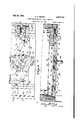
July 30 1940 G. R; GlBsoN LOCKING MECHANISM FOR CABINET DRAWERS s sheets-sheet 2 Filed Oct. 14. 1938 .LLIIIIIIIQNII I4.
bson,
Geb
'uly 30, 1940. G. R-.yGlBsoN 2,209,727
LOCKING MECHANISM FOR CABINET' DRAWERS Filed Oct. 14. 195s s Smets-sheet s I O l /zg z 22 GeogelG/Zson,
Patented July 30, 1940 PATENTl OFFICE` LOCKING MLEGHANISM FOR CABINET DRAWERS George Bloscoe Gibson, Brookfield, Ohio, as-
signer to The General Fireprooling Company, Youngstown, Ohio, a corporation of Ohio Application October 14,
Claims.
rlhis invention relates to flreproof cabinets, and more particularly to a novel mechanism for automatically latching the individual drawers in closed position and also locking the same when desired through a common manually controlled 5- handle.
In certain-types of storage cabinets, particularly those intended to store iilms or other combustible material, it is necessary to keep the same 4 closed except when removing or replacing a lm. To that end the present invention proposes to mount the drawers so that the operator must hold the drawer open by pulling the same forward, and when the pulling force is released, the drawer will automatically slide or gravitate to closed position and become latched against accidental opening by pressure from within. While the cabinet -is provided with suitable venting means connected to a iiue so that if the contents of a particular drawer should become ignited the so major force of the consequent combustion will pass out the flue, nevertheless the drawer itself, due to the present invention, will not be forced open to endanger the occupants of the room or spread the conflagration. Hence, the drawer not only automatically slides to a closed position when released, but, at the same time, it becomes latched to prevent accidental opening. Moreover, it is desirable to also provide a positive lock or bolt which will not only augment, or supplement, the holding effect produced by the latches but also serve to wedge or seal the drawer in the cabinet when the drawer is not in immediate use. `,Another object of the invention is to provide a drawer mounted to automatically slide to a closed position with novel latching and locking means controlled by single manual element. Thus, the operator may readily control the latch for opening the drawer, and on the other hand, lock or bolt the drawer byproper manipulation of the handle, in a diierent direction.
A further object of the invention is to providey a simple and practical operating construction which lends itself to standard manufacturing practices, and which in use is reliable and efiicient.
With the above and other objects in view which will more readily appear as the nature of the invention `is better understood, the same consists 50 in the novel construction, combination and arrangement of parts hereinafter more fully described, illustrated and claimed.
A preferred and practical embodiment of the invention is shown in the accompanying draw'- 55 ings, in which:
1938, Serial No. 235,037
Figure 1 is a front elevation of a drawer and part of the cabinet embodying the present improvements.
Figure 2 is a vvertical longitudinal sectional view of a drawer compartment having the drawer therein. 5
Figure 3 is an enlarged detail elevation of the improved latching and locking means.
Figure 4 is a horizontal sectional view taken on the line 4--4 of Figure 3.
Figure 5 is a detail vertical sectional View taken on the line 5-5 of Figure 3. I
Figure 6 is a detail sectional view taken on the line 'l-l of Figure 3.
Figure 7 is a detail sectional view taken on the 15 line 6 6 of Figure 3.
Figures 8, 9 and 10 are diagrammatic views illustrating the several positions of the latch and lock means in different positions of the manually controlled handle.
Similar reference characters designate corre-` sponding parts throughout the several figures of the drawings.
The drawer designated generally as A is slidably mounted within the compartment B" of the cabinet, which, as previously indicated, may be 25 provided with the venting means C. The drawer is'y mounted on a suitable sliding drawer guide designated as D in dotted lines in Figure 2, the said drawer guide being mounted at an angle so that the drawer will automatically slide or move to its closed position.
The drawer A is provided with a head E having suitable insulating material 'molded therein eX- cept for a compartment E2 at the front thereof which houses the means for operating the latch 35.
and lock elements. This compartment is covered by a front panel F whose top and side edges are framed-by a part of the metallic casing which constitutesl the major portion of the drawer head.
Referring to Figures 3, 4 and 5 it` will be ob- 40 served that the drawer head includes in` its organization suitable reinforcing means for carry ing and supporting the latch and lock mechanism and also forming a strong and rigid drawer head. For example, the reinforcing means includes in its organization a pair of inwardly facing vertical channel members G--G, which are preferably coextensive vertically with the ends of the drawer head and are connected by the transversely arrang-ed cross member or strap I-I. The end portions I-I of said strap are slightly offset inwardly to lie behind the forward wings of the channel members G-G. This transverse cross piece or strip I-I not only braces'fand connects the inwardly facing channel members but also forms the primary rigid base for the latching and locking mechanism.
The means for holding the drawer in the cabinet essentially includes one or more latch and lock units preferably arranged at opposite sides of the drawer head, and a controlmeans arranged centrally of the drawer head. Since the latch and lock means of each unit are similar in construction, a description of one unit will suce for both.
The side of the cabinet adjacent each latch and lock unit, preferably provided with a keeper Opening I of substantially elongated stepped formation at its front edge to receive the beveled latched end of a latch 2 and the locking end of a sliding bolt 3. The latch 2 and the bolt 3 are super-imposed for slidable movement within a housing 4 (Figs. 3, 4 and 7) which consists of a transversely arched plate `having the flanges -5 which may be securedto the outer face of one of the wings of the upright channel members G-G 4by spot welding 6 or otherwise. The latch 2.is provided at itsv upper side with a recess I for receiving a coil spring 8 whose forward end engages one of the vertical walls of the recess while its rearend engages thev downturned flange portion 9 of anr abutment member Ill. This member is secured tothe upper flange 5 of the housing by a screw or equivalent fastening II. It will, of course, be observed that the upper wall 4EL of the housing 4 is suitably slotted to admit the downturnedend- 9 of the abutment II) into the recess 'l of the latch to afford an abutment or stop for the rear end of the spring 8. The purpose of the spring 8, ar-
ranged as described, is to force the latch normally outward, or, in other words, to project the latch automatically toward thekeeper I.
The bottom of the latch 2 is provided with an oiset portion I2 which provides spaced shoulders I3 and I4. The offset portion I2 including the shoulders referred to ts into a recess I5-of the bolt 3. a shoulder I5a for engaging with the shoulder I3 of the latch and a shoulder Ib for engaging with the shoulder I4 at the rear of the latch. It will also be understood from the drawings that theshonlders ,I3 and` I4'are spaced. closer together than the distance between the shoulders I5a and I5b on the bolt 3 softhat the movement of the bolt 3 toward locking is greater than the movement of the'latch'2 to latchingposition.
The vsliding bolt 3 is pivotallyv connected at its rear end, as indicated at I 6; with a link-Il. This link is pivotally connected as indicated at I8 with a dial or disc member `I9 of the manual control mechanism designated as M.
The control mechanism including the dial or disc IS is supported on the transverse plate or strip H previously referred to. As will be observed from Figures 3, 4 and 5 the dial I 9 is provided with a square opening I9a for receiving a square or equivalent portion 20 carried by the shaft 2| which includes the angularly disposed operators handle 22. This shaft in addition to carrying the square or other key portion 20 is provided with portions 23 and 24 of different diameter. The portion 23 which is of less diameter than the portion 24 is journaled in a plate 25 carried by the'strip H, and projects through registering openings in the plate and strap to receive avlock nut 2li.v This nut` is accessible through a Well 2I formed in the rear metallic This recess, in turn, provides wall of the drawer head. The portion 24 of the handle shaft which is of larger diameter than the portion 23 is journaled in the front wall of an arched plate 28 which lies immediately behind the panel F of the drawer head. This plate 28 is provided with the offset flanges 29 secured to the plate 25 .by suitable fastenings 30.
The dial I9 is provided with a peripheral notch 3l having a stop shoulder 32 and a friction shoulder 33 at opposite ends thereof. This notch is intended to receive the friction pin 34 of a spring pressed pawl or detent 35 pivotally supported as at 36 on the transverse strip H. A spring 3l is employed to urge the friction pin 34 of the pawl or detent into the notch 3I.
As will be apparent from Figures 3 and 4 the dial I0 which is under the control of the handle 22, has the link members I'I-II of opposite lock and latch units pivotally connected thereto at diametrically opposite points IIS-I8. It will, therefore, be seen that a partial rotation of. the dial or disc through the handle 22 will, in turn, impart movement to the links, and this movement will be transmitted to the sliding bolts 3.
The normal position of the latch and lock means is shown in Figures 3, 4, 5 and 8 of the drawings. From these views it will be observed, particularly with reference to Figure 8, that kwhen the parts are in their normal position, the handle I8 is in its vertical position so that the bolts 3 are retracted while the latches 2 are projected by the springs 8 toward the keeper means I in the sides of the drawer cabinet. Thus, in this position, the drawer head is held in its latched position in the cabinet. If it is desired to open the drawer it is only necessary to move the handle 22 to the right in Figure 9 which wilLcause the dial I9 to turn counter-clockwise and thus operate the links I'I to pull the bolts 3 inwardly. When the bolts are thus pulled inwardly, thev shoulders I5a on the bolts will engage the shoulders I 3 on the latches and draw the latter inwardly against the force of the springs 8. Thus, the latches are released from the keepers and the drawer may be pulled open. To prevent the handle 22 from being turned too far in an anticlockwise direction, the friction pin 34 of the detent 35 will engage the locking shoulder 32 of the notch 3l in the periphery of the dial.
When the handle 22 is released from the position shown in Figure 9 the springs 8 will force the latches 2 outwardly or in other words project them laterally and thus pull the bolts 3 along with them and return the handle 22 to the normal vertical position shown in Figure 8.
If. it is desired to lock the drawers in the compartments of the cabinets and against the seal S, the bolts S are actuated so as to project them into the keepers I by rotating the handle 22 in a clockwise direction, as shown in Figu re 10. When the handle is turned in this direction, the friction pin 34 will ride over the shoulderv 33 of the notch and the consequent movement of the dial I9 will force the links I'I outwardly. This movement will force or project the bolts 3 toward the keeper means, and, in so doing the shoulders la of the bolts will pull away from the shoulders I3 of the latches and the shoulders I5b will engage the shoulders I4 of the latches, thereby not only forcing the bolts into the keepers but at the same time holding the latches 2 in their projected positions. When it is desired to unlock the drawer by releasing the bolts 3 it is only necessary to turn the handle 22 in an anti'- The shoulder 33, due `to its engagement with the pin 3B, when the parts are in the position shown in Figure 8, also prevents the latches 2 from kicking out the bolts 3 as the said latches are forced forward by the springs 8v when the drawer automatically closes. That is to say, assuming the drawer is in its closed and latched position, the latches 2 and the handle 22 assume the position shown in Figure 8. If it is desired to unlatch the drawer, for opening, the handle 22 is moved to the position shown in Figure 9, as
previously described. If the operator releasesv the handle `22, the force of the springs 8 will shift bolts 3 back to the position shown in Figure 8, likewise force the handle 22 back to the vertical position shown in said ligure. When the door gravitates to closed position the latches 2 will be forced inwardly as they pass over the frame parts leading to the keepers. This will compress the springs 8. When the latches 2 register with the keeper openings l the springs will release their stored energy and, therefore, the shoulders i3 and l5@ will come together with a force which would tend to kick out the' bolts 3 a suicient .distance to make them engage the keeper opening l and thus llock the drawer. Therefore, the shoulder 33 when engaged with 34 prevents this accidental movement of the bolts 3 since the engagement of the shoulder 33 and pin 34 prevents movement of the dial and the lengths Il connected with the bolts.
From the foregoing description, it will be apparent that the present invention provides a cabinet including a drawer slidably mounted to move to closed position within a compartment of a cabinet, the said drawer having latch means for automatically holding the drawer withinthe compartment, and said latch means being adapted to be controlled by an operators control element which also actuates the means for locking or bolting the drawer in sealed position. By a simple manipulation of the manual control means the drawer may be readily opened and closed, while on the other hand, when it is desired, it may be securely pressed or locked in closed position.
I claim:
1. Combined latch and lock means for closures, comprising, latch means adapted to automatically engage a keeper means for holding the drawer against accidental opening, lock means, and manually controlled handle operated means movable to one side of a normal vertical position to withdraw the latch means from the keeper means and movable to the other side of said normal position to force the lock means into engagement with the keeper means.
2. A closure fastener, comprising, latch and lock means, springs for causing the latch means to be automatically projected, and manually controlled means for projecting and retracting said lock means while the latch means are projected, said latch and lock means having cooperating parts whereby a portion of the retracting movement of the lock means also retracts the latch means.
3. A closure fastener, comprising combined latch and lock units, each of said units including a spring pressed latch having an offset portion and a sliding bolt having arecessed portion for receiving said offset portion of the latch, said recess being a greater length than the offset portion to permit the bolt to slide outwardly free of the latch to effect locking of the drawer, and one end of the recessed portion of the bolt and one end of the offset portion of the latch adapted to cooperate when the bolt slides inwardly to thereby retract the spring pressed latch, and
means for controlling the latch and lock means of said units. l
4. A closure fastener, comprising, combined latch and lock units, each of said units including a spring pressed latch having an oiset portion and a sliding bolt having a recessed portion for receiving said offset portion of the latch,'said recess being a greater length than the offset portion to permit the bolt to slide outwardly free ofthe latch to effect locking of the closure, and one end of the recessed portion of the bolt 'and one end of the offset portion of the latch adapted to cooperate when the bolt slides inwardly to thereby retract the spring pressed latch; and means for controlling the latch and lock ,means of said units, said last named means including a disc, a handle exposed at the outer side of the drawer head and having a shaft portion engaged with `said disc, link means pivotally connecting said bolt with the disc at a point between the axis of the` disc and its periphery, and means for limiting the movement of the disc.
5. A closure fastener, comprising, manually controlled mechanism for controlling the latch# ing and locking of said closure, said mechanism including supporting means within the closure comprising inwardly facing channel members and a transverse plate connecting the front wings of said channel members, latch and bolt units slidable in housings carried by the front faces of the front wings of said channel members at the location of said transverse plate, springs for automatically projecting said latch means, sliding bolts constituting said lock means, an oscillatable member, a handle exposed at the outer face of the closure and having a shaft keyed to said oscillatable member, said shaft also having a portion journaled in said transverse plate,'link means connecting the oscillatable member with the sliding bolts, and cooperating inter-engaging parts on the latch and lock means whereby the manipulation of the oscillatable member through the handle will control the projection and con= traction of the latch means and also permit the bolt to move to locking position independently of said latch means. y
6. A closure fastener, comprising, a latch and bolt housing supported within the closure, a recessed bolt slidable on a portion of the housing, a latch having an offset portion slidably mounted within the recessed portion of the bolt, a spring within the housing for forcing the latch to projected position, an oscillatable member, a housing for said oscillatablemember including a rear plate and a front transversely arched plate having flanges secured to said rear plate, a shaft journaled in said front and rear plates of the housing for the oscillatable member and having a handle exposed at the outer face of the closure, said oscillatable member -being keyed to said shaft for movement therewith, link means connecting said oscillatable member with said bolt, and'means for limiting the movement of said oscillatable member.
'7; A closure-fastener,comprising, a latch and bo1t unit within the closure for cooperation with said keeper means, a spring for projectinga latch automatically to a position to engage said keeper means, a bolt having spaced shoulders for alternately engaging cooperatingV shoulders on the latch and spaced closer together than the shoulders on the bolt, a handle constituting a lever, an oscillatable member controlled by said handle, link means between said oscillatable link means and said bolt, and spring pressed detent means for limiting the movement of said oscillatable member.
8. Al closure.v fastener, comprising, slidably mounted inter-engaged latch and bolt members for cooperation. with a keeper means, a spring for normally projecting saidI l latch into said keeper.- means, 4and manually operated handle means for actuating said bolt, said handle means 'comprising a disc adapted to be oscillated by said handle, a link connecting said disc with said sliding bolt, said dischaving a notch provided with a locking shoulder and a friction shoulder, and a spring pressed detent having a friction stud adapted to ride n said notch and engage the locking shoulder thereof when the handle is turned to Withdraw thc bolt and the latch and to engage said friction shoulder and ride out of the notch when the handle is turned to release the latch and move said locking bolt into locking engagement with the keeper means.
9. Closure fastening means comprising, a closure-carried locking bolt projectable into and retractable from closure locking .cooperation with a keeper, meansvfor projecting andY retracting said bolt, a closure-,carried latch, spring means tending constantly to. project said latch4 into closure latching cooperation With said keeper, and av lost motion connection lbetween said locking bolt and said latch permitting the latch to be projected by its spring into said. keeper When the locking bolt is projected and also when the locking bolt is in a predetermined retracted, closureunlocking position, said connection including means to retract said latch from said keeper and hold it retracted therefrom by retraction of said locking bolt to a position beyond its aforesaid predetermined retracted position.
10. Closure fastening -means comprising a closure-carried locking bolt projectable into and retractable from closure locking cooperation with a keeper, means for projecting and retracting said bolt, a closure-carried latch, spring means tendingk constantly to project said latch into closure latching cooperation with said keeper, and a lost motion connection between said locking bolt and said latch permitting the latch to be projected by its spring into said keeper when the locking bolt is projected and also when the locking bolt is in a predetermined retracted, closure-unlocking position, said connection including cooperat ing shoulders on said bolt and said keeper effective to retract said latch from said keeper and hold it retracted therefrom by retraction of said locking bolt to a position beyond its aforesaid predetermined retracted position.
GEORGE ROSCOE GIBSON.
Priority Applications (1)
| Application Number | Priority Date | Filing Date | Title |
|---|---|---|---|
| US235037A US2209727A (en) | 1938-10-14 | 1938-10-14 | Locking mechanism for cabinet drawers |
Applications Claiming Priority (1)
| Application Number | Priority Date | Filing Date | Title |
|---|---|---|---|
| US235037A US2209727A (en) | 1938-10-14 | 1938-10-14 | Locking mechanism for cabinet drawers |
Publications (1)
| Publication Number | Publication Date |
|---|---|
| US2209727A true US2209727A (en) | 1940-07-30 |
Family
ID=22883817
Family Applications (1)
| Application Number | Title | Priority Date | Filing Date |
|---|---|---|---|
| US235037A Expired - Lifetime US2209727A (en) | 1938-10-14 | 1938-10-14 | Locking mechanism for cabinet drawers |
Country Status (1)
| Country | Link |
|---|---|
| US (1) | US2209727A (en) |
Cited By (12)
| Publication number | Priority date | Publication date | Assignee | Title |
|---|---|---|---|---|
| US2628117A (en) * | 1948-12-22 | 1953-02-10 | Stanley Works | Latch operating mechanism |
| US2810616A (en) * | 1955-03-07 | 1957-10-22 | Meilink Steel Safe Company | Bolt locking mechanism |
| US2833364A (en) * | 1954-08-13 | 1958-05-06 | Int Harvester Co | Motor vehicle engine enclosure construction |
| US2868310A (en) * | 1954-08-13 | 1959-01-13 | Int Harvester Co | Motor vehicle fender locking means |
| US2956525A (en) * | 1957-09-11 | 1960-10-18 | Diebold Inc | Security file multi-bolt locking mechanism |
| US2969666A (en) * | 1957-07-03 | 1961-01-31 | Kawneer Co | Lock and latch assembly |
| US3862772A (en) * | 1973-12-12 | 1975-01-28 | Bentson Ind Inc | Safety stop lock |
| US4046410A (en) * | 1976-05-27 | 1977-09-06 | Connell Robert I | Four way security door |
| US4615095A (en) * | 1984-02-03 | 1986-10-07 | Knape & Vogt Manufacturing Company | Inclined drawer slide incorporating scale |
| US6935660B1 (en) * | 2001-09-12 | 2005-08-30 | Mobile Mini, Inc. | Premium door locking system |
| US20110037365A1 (en) * | 2009-08-14 | 2011-02-17 | King Slide Works Co., Ltd. | Undermount drawer slide |
| US7901017B1 (en) * | 2007-07-02 | 2011-03-08 | Corry Contract, Inc. | Security file cabinet with self-closing, self-locking drawers |
-
1938
- 1938-10-14 US US235037A patent/US2209727A/en not_active Expired - Lifetime
Cited By (13)
| Publication number | Priority date | Publication date | Assignee | Title |
|---|---|---|---|---|
| US2628117A (en) * | 1948-12-22 | 1953-02-10 | Stanley Works | Latch operating mechanism |
| US2833364A (en) * | 1954-08-13 | 1958-05-06 | Int Harvester Co | Motor vehicle engine enclosure construction |
| US2868310A (en) * | 1954-08-13 | 1959-01-13 | Int Harvester Co | Motor vehicle fender locking means |
| US2810616A (en) * | 1955-03-07 | 1957-10-22 | Meilink Steel Safe Company | Bolt locking mechanism |
| US2969666A (en) * | 1957-07-03 | 1961-01-31 | Kawneer Co | Lock and latch assembly |
| US2956525A (en) * | 1957-09-11 | 1960-10-18 | Diebold Inc | Security file multi-bolt locking mechanism |
| US3862772A (en) * | 1973-12-12 | 1975-01-28 | Bentson Ind Inc | Safety stop lock |
| US4046410A (en) * | 1976-05-27 | 1977-09-06 | Connell Robert I | Four way security door |
| US4615095A (en) * | 1984-02-03 | 1986-10-07 | Knape & Vogt Manufacturing Company | Inclined drawer slide incorporating scale |
| US6935660B1 (en) * | 2001-09-12 | 2005-08-30 | Mobile Mini, Inc. | Premium door locking system |
| US7901017B1 (en) * | 2007-07-02 | 2011-03-08 | Corry Contract, Inc. | Security file cabinet with self-closing, self-locking drawers |
| US20110037365A1 (en) * | 2009-08-14 | 2011-02-17 | King Slide Works Co., Ltd. | Undermount drawer slide |
| US8231189B2 (en) * | 2009-08-14 | 2012-07-31 | King Slide Works Co., Ltd. | Undermount drawer slide |
Similar Documents
| Publication | Publication Date | Title |
|---|---|---|
| US2209727A (en) | Locking mechanism for cabinet drawers | |
| US3678716A (en) | Latch mechanism for refrigerators freezers and the like | |
| US9260890B2 (en) | Latch mechanism | |
| US3209564A (en) | Door control mechanism | |
| US3084008A (en) | Automatic locking key safe | |
| US1075914A (en) | Lock. | |
| US2967080A (en) | File cabinet locking device | |
| US1870746A (en) | Automatic safe doorlock | |
| US2379157A (en) | Locking mechanism for file drawers | |
| US3565476A (en) | Hood latch assembly | |
| US2032019A (en) | Lock for interlocking fasteners | |
| US3193315A (en) | Door latches | |
| US1168525A (en) | Door-lock. | |
| US2142456A (en) | Coach lock | |
| US2655027A (en) | Door latch | |
| US857922A (en) | Sliding-door fastener. | |
| US358632A (en) | teller | |
| US1593372A (en) | Refrigerator-door fastener | |
| US1370942A (en) | Locking mechanism | |
| US2664736A (en) | Door lock | |
| US1458200A (en) | Wall receptacle for receiving deliveries | |
| US712078A (en) | Lock. | |
| US809058A (en) | Mail-pouch fastener. | |
| US1274610A (en) | Latch. | |
| US818443A (en) | Locking device. |