US809058A - Mail-pouch fastener. - Google Patents
Mail-pouch fastener. Download PDFInfo
- Publication number
- US809058A US809058A US26684405A US1905266844A US809058A US 809058 A US809058 A US 809058A US 26684405 A US26684405 A US 26684405A US 1905266844 A US1905266844 A US 1905266844A US 809058 A US809058 A US 809058A
- Authority
- US
- United States
- Prior art keywords
- staples
- bolt
- engaging
- flap
- strap
- Prior art date
- Legal status (The legal status is an assumption and is not a legal conclusion. Google has not performed a legal analysis and makes no representation as to the accuracy of the status listed.)
- Expired - Lifetime
Links
- 238000010276 construction Methods 0.000 description 3
- 230000032683 aging Effects 0.000 description 1
- 238000000034 method Methods 0.000 description 1
- 230000000284 resting effect Effects 0.000 description 1
Images
Classifications
-
- B—PERFORMING OPERATIONS; TRANSPORTING
- B65—CONVEYING; PACKING; STORING; HANDLING THIN OR FILAMENTARY MATERIAL
- B65D—CONTAINERS FOR STORAGE OR TRANSPORT OF ARTICLES OR MATERIALS, e.g. BAGS, BARRELS, BOTTLES, BOXES, CANS, CARTONS, CRATES, DRUMS, JARS, TANKS, HOPPERS, FORWARDING CONTAINERS; ACCESSORIES, CLOSURES, OR FITTINGS THEREFOR; PACKAGING ELEMENTS; PACKAGES
- B65D29/00—Sacks or like containers made of fabrics; Flexible containers of open-work, e.g. net-like construction
Definitions
- WITNESSES .l/VVEIVTOR 'azinw ATTORNEYS UNITED STATES PATIENT OFFICE.
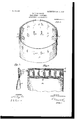
- Figure 1 is a perspective view of a mail-pouch provided with my improved fastener.
- Fig. 2 is a plan view of the flap.
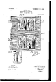
- Fig. 3 is a longitudinal vertical section through one of the locks.
- Fig. 4 is a plan view of the locks with the top plates removed, showing the locking-bolts in engagement with the staples.
- Fig. 5 is a similar view showing the locking-bolts out of engagement with the staples.
- Fig. 6 is a plan view of the lower face of a top plate provided with means for locking the locking-bolt
- Fig. 7 is a perspective view of the key.
- I provide a mail-pouch A of ordinary construction having upon one side of the open end thereof a series of transverse staples a, and upon the other side of the open end a series of slots (i adapted to receive the staples.
- a flap B Secured to the side of the pouch provided with the staples is a flap B, provided with slots 1) for receiving the staples and with a longitudinal opening I) therethrough adjacent the ends of the staples for a purpose to be hereinafter described.
- a lock O is provided for each of the staples, comprising in the present instance a casing composed of two plates, the lower plate 0, secured to the flap and having a slot 0 registering with the slot in the flap, and an opening a registering with the longitudinal opening in the flap.
- locking-bolt 0 having the general shape shown in Fig. 5 and provided with a slot 0 en aging aflange c on the lower plate, is provi ed for engaging the staple, a recess 0 being provided therein for receiving the side of the staple.
- a spring-latch is pivoted to the lower plate and is provided with a lug c for engaging a lug c on the bolt to hold the bolt either in its locked or unlocked position, a spring 0 normally maintaining the latch in engagement with the bolt.
- a lever 0 having an arm 0 extending over the opening c ,the opposite end being provided with a cam 0 engaging a cam-surface 0 on the latch for actuating the same.
- a strap D arranged in the longitudinal opening I) of the flap, is provided with lugs d for engaging the extended arm of the lever 0 a perforation (1 being provided through the end of the strap, the pouch, and the flap and adapted to be engaged by a lock d to prevent movement of the strap with relation to the flap.
- a ring d is provided on the end of the strap for convenience in manipulating the same.
- the lock (1 may be dispensed with, in which case I provide mechanism in one of the end locks for securing the lockingbolt thereof in its locked position.
- This mechanism comprises in the present instance a lever E, pivoted to the upper plate and provided with a lug e for engaging behind the locking-bolt and a forwardly-extending arm 6, adapted to be engaged by a key 6 introduced through a keyhole e in the plate, the spring e normally retaining the lug in its outward position.
- strap may be secured by a padlock, or the bolt of the end lock may be locked by a key, as desired.
- a padlock or the bolt of the end lock may be locked by a key, as desired.
- To open the pouch it is necessary simply to remove the padlock or to unlock the end lock, when a pull on the strap of the latch releases all of the staples simultaneously.
- a pouch provided with the improvement may be opened and closed in a very short space of time, much shorter than with the old style of pouch, where it is necessary to thread the strap through the staples.
- a mail-pouch comprising an open sack having one of the sides of its open end provided With a transverse series of staples, and the opposite side provided with a transverse series of slots for receiving the staples, a fla secured to the first side and provided Witli transverse slots to receive the staples and with a longitudinal opening therethrough adjacent to the staples, a series of locks for the staples, comprising each a plate secured to the flap and provided with an opening registering with the slot in the flap and with an opening registering with the longitudinal opening in the -flap, a locking-bolt slidably mounted on the plate and adapted to engage a staple, a lug on the bolt, a latch pivoted to the plate and provided with a lug engaging with the lug on the bolt, a spring for normally maintaining the latch in engagement with the bolt, a lever pivoted to the plate for actuating the lockin -bolt, a cam on the lever for actuating the atch to release the bolt, an arm on the lever extending over the
- a flap having openings to receive the staples, of a series of locks for the staples each comprising a casing having an opening to receive the staple, means within the casing for engaging the staple to lock the same, means within the casing for retaining said engaging means in position, means Within the casing for actuating the locking means and for simultaneously releasing the retaining means, and a single means engaging the actuating means of each of the series for simultaneously actuating the locking means.
- a mail-pouch provided with a series of staples and a flap having openings to receive the staples, of a series of locks for the staples, comprising each a casing having an opening to receive the staple, means Within the casing for engaging the adjacent staple, means for retaining the engaging means in position, means for actuating said engaging means and for simultaneously releasing the retaining means, and a single means engaging each of the actuating means of the series of locks for simultaneously actuating the staple-engaging means.
Landscapes
- Engineering & Computer Science (AREA)
- Mechanical Engineering (AREA)
- Portable Nailing Machines And Staplers (AREA)
Description
PATENTED JAN. 2, 1906.
L. H. HINAMAN. MAIL POUCH PASTENER.
APPLICATION FILED JUNE 24,1905.
2 SHEETS-SHEET 1.
WITNESSES:
m m n H N0. 809,058. PATENTED JAN. 2, 1000. Y L. H. HINAMAN.
MAIL POUCH PASTENER.
APPLICATION FILED JUNE 24,1905.
2 SHEETS-SHEET 2.
WITNESSES: .l/VVEIVTOR 'azinw ATTORNEYS UNITED STATES PATIENT OFFICE.
LOUIS H. HINAMAN, OF PORT J ERVIS, NEW YORK, ASSIGNOR OF THREE- FOURTHS TO TITUS HINAMAN, OF KELLAM, PENNSYLVANIA.
MAIL-POUCH FASTENER- Specification of Letters Patent.
Patented Jan. 2, 1906.
To all whom, it may concern.-
Be it known that I, Louis E. HINAMAN, a citizen of the United States, and a resident of Port Jervis, in the county of Orange and State of New York, have invented certain new and useful Improvements in Mail-Pouch Fasteners, of which the following is a specification. My invention is an improvement in mailpouch fasteners; and it consists in certain novel constructions and combinations of parts hereinafter described and claimed.
Referring to the drawings forming a part hereof, Figure 1 is a perspective view of a mail-pouch provided with my improved fastener. Fig. 2 is a plan view of the flap. Fig. 3 is a longitudinal vertical section through one of the locks. Fig. 4 is a plan view of the locks with the top plates removed, showing the locking-bolts in engagement with the staples. Fig. 5 is a similar view showing the locking-bolts out of engagement with the staples. Fig. 6 is a plan view of the lower face of a top plate provided with means for locking the locking-bolt, and Fig. 7 is a perspective view of the key.
In the practical application of my invention I provide a mail-pouch A of ordinary construction having upon one side of the open end thereof a series of transverse staples a, and upon the other side of the open end a series of slots (i adapted to receive the staples. Secured to the side of the pouch provided with the staples is a flap B, provided with slots 1) for receiving the staples and with a longitudinal opening I) therethrough adjacent the ends of the staples for a purpose to be hereinafter described.
A lock O is provided for each of the staples, comprising in the present instance a casing composed of two plates, the lower plate 0, secured to the flap and having a slot 0 registering with the slot in the flap, and an opening a registering with the longitudinal opening in the flap. The top plate 0, having a flange resting upon the lower plate and secured thereto by rivets or screws e is provided with a recess to receive the end of the sta le.
locking-bolt 0 having the general shape shown in Fig. 5 and provided with a slot 0 en aging aflange c on the lower plate, is provi ed for engaging the staple, a recess 0 being provided therein for receiving the side of the staple. A spring-latch is pivoted to the lower plate and is provided with a lug c for engaging a lug c on the bolt to hold the bolt either in its locked or unlocked position, a spring 0 normally maintaining the latch in engagement with the bolt. Within a recess c on the upper face of the locking-bolt is a lever 0 having an arm 0 extending over the opening c ,the opposite end being provided with a cam 0 engaging a cam-surface 0 on the latch for actuating the same. A strap D, arranged in the longitudinal opening I) of the flap, is provided with lugs d for engaging the extended arm of the lever 0 a perforation (1 being provided through the end of the strap, the pouch, and the flap and adapted to be engaged by a lock d to prevent movement of the strap with relation to the flap. A ring d is provided on the end of the strap for convenience in manipulating the same.
It will be understood that the above description applies to each of the locks, the strap engaging the. actuating-lever in each lock, whereby a pull on the strap simultaneously locks or releases all of the staples.
If desired, the lock (1 may be dispensed with, in which case I provide mechanism in one of the end locks for securing the lockingbolt thereof in its locked position. This mechanism comprises in the present instance a lever E, pivoted to the upper plate and provided with a lug e for engaging behind the locking-bolt and a forwardly-extending arm 6, adapted to be engaged by a key 6 introduced through a keyhole e in the plate, the spring e normally retaining the lug in its outward position. When the key is rotated onehalf round, the lug will be thrown out of contact with the locking-bolt, allowing free movement of the same in either direction. When the strap is pulled to unlock the staples and the key is removed from the look, a pull on the strap to lock the staples allows the lug to engage behind the locking-bolt to prevent unlocking of the same until the lug is again moved out of place with the key, It will be evident that with one of the lockingbolts locked 'all are locked, since they must move simultaneously.
In operation the flap is drawn down u on the staples and the strap is pulled to the eft, thus moving all of the locking-bolts into engagement with the respective staples. The
strap may be secured by a padlock, or the bolt of the end lock may be locked by a key, as desired. To open the pouch, it is necessary simply to remove the padlock or to unlock the end lock, when a pull on the strap of the latch releases all of the staples simultaneously.
It will be evident from the description that my improved fastener, while simple in construction, is eflicient and easily operated.
this case to provide a new flap or to provide an old flap with the openings for the strap. The appearance of the pouch will be but little changed, and the natural method pursued in opening the old style of pouchthat is, ulling the strap from the stapleswill resu t in opening a pouch provided With my improvement. A pouch provided with the improvement may be opened and closed in a very short space of time, much shorter than with the old style of pouch, where it is necessary to thread the strap through the staples.
Having thus described my invention, what I claim as new, and desire to secure by Letters Patent, is
1. A mail-pouch comprising an open sack having one of the sides of its open end provided With a transverse series of staples, and the opposite side provided with a transverse series of slots for receiving the staples, a fla secured to the first side and provided Witli transverse slots to receive the staples and with a longitudinal opening therethrough adjacent to the staples, a series of locks for the staples, comprising each a plate secured to the flap and provided with an opening registering with the slot in the flap and with an opening registering with the longitudinal opening in the -flap, a locking-bolt slidably mounted on the plate and adapted to engage a staple, a lug on the bolt, a latch pivoted to the plate and provided with a lug engaging with the lug on the bolt, a spring for normally maintaining the latch in engagement with the bolt, a lever pivoted to the plate for actuating the lockin -bolt, a cam on the lever for actuating the atch to release the bolt, an arm on the lever extending over the o ening in the plate, a second plate inclosing t e look, a lever pivoted to the second plate and provided wit a lug for engaging the sliding bolt, means whereby the lever may be actuated to release the lug from the lockingbolt, means for simultaneously actuating the series of locks comprising a flexible strap in the longitudinal opening in the flan, the strap for engaging the arms of t lugs on e levers,
and a look traversing the ends of the strap and the pouch for preventing movement of the strap.
2. The combinationwitha'mail-pouchprovided with a transverse series of staples, and a flap having openings to receive the staples, locks for the staples comprising each acasing having an opening to receive the staples, a locking-bolt in the casing for engaging the staple, a latch for locking the bolt in position, a lever for actuating the bolt, a cam on the lever for releasing the latch, a lever pivoted within the casing, a lug on the lever for engaging the bolt to retain it in its locked position, means for releasing the lug, a strap Within the fla and provided with lugs for engaging the en s of the actuating-levers whereby the bolts may be actuated simultaneously, and means for preventing movement of the strap.
3. The combination with a mail-pouch provided with a transverse series of staples, and a flap havin openings to receive the staples, of locks for the staples comprising each a casing having an opening to receive the staple, a lockin bolt within the casing for engaging the staple, a latch for locking the bolt 1n osition, a lever for actuating the lockingolt, a cam on the lever for releasing the latch, and a strap within the flap and provided with lugs for engaging the actuating levers whereby the locking bolts may be actuated simultaneously.
4. The combination with a mail-pouchprovided with a transverse series of staples and a flap havin openings to receive the staples, of locks for the staples comprising each a casing having an opening to receive the staples, a locking-bolt within the casing for engaging the staples, a latch for locking the bolt in position, a lever for actuating the bolt, means on the lever for releasing the latch, means within the fla for engaging the actuatinglevers to simu taneously actuate the lockingbolts, means within the casing of one of the locks for retaining the lock1ng-bolt in its locked position, and means for releasing said retaining means.
5. The combination of a mail-pouch provided with a transverse series of staples and.
a flap having openings to receive the staples, of a series of locks for the staples each comprising a casing having an opening to receive the staple, means within the casing for engaging the staple to lock the same, means within the casing for retaining said engaging means in position, means Within the casing for actuating the locking means and for simultaneously releasing the retaining means, and a single means engaging the actuating means of each of the series for simultaneously actuating the locking means.
6. The combinationwith a mail-pouchprovided with a series of staples and a flap having openings to receive the staples, of a series of locks for the staples, comprising each a casing having an opening to receive the staple, means Within the casing for engaging the adjacent staple, means for retaining the engaging means in position, means for actuating said engaging means and for simultaneously releasing the retaining means, and a single means engaging each of the actuating means of the series of locks for simultaneously actuating the staple-engaging means.
7. The combination With a mail-pouch provided With a transverse series of staples, and a flap having openings to receive the staples,
of a series of locks for the staples, comprising a casing having an o ening to receive the staple, means Within tlie casing for engaging the staples to lock the same, means for retaining the locking means in osition and single means for simultaneous y actuating each of the staple-engaging means, and forre- 2o leasing the retaining means.
LOUIS H. HINAMAN.
Witnesses B. B. CHonE, W. W. BOSTREE.
Priority Applications (1)
| Application Number | Priority Date | Filing Date | Title |
|---|---|---|---|
| US26684405A US809058A (en) | 1905-06-24 | 1905-06-24 | Mail-pouch fastener. |
Applications Claiming Priority (1)
| Application Number | Priority Date | Filing Date | Title |
|---|---|---|---|
| US26684405A US809058A (en) | 1905-06-24 | 1905-06-24 | Mail-pouch fastener. |
Publications (1)
| Publication Number | Publication Date |
|---|---|
| US809058A true US809058A (en) | 1906-01-02 |
Family
ID=2877539
Family Applications (1)
| Application Number | Title | Priority Date | Filing Date |
|---|---|---|---|
| US26684405A Expired - Lifetime US809058A (en) | 1905-06-24 | 1905-06-24 | Mail-pouch fastener. |
Country Status (1)
| Country | Link |
|---|---|
| US (1) | US809058A (en) |
Cited By (2)
| Publication number | Priority date | Publication date | Assignee | Title |
|---|---|---|---|---|
| US2710639A (en) * | 1953-04-24 | 1955-06-14 | Genevieve M Farls | Multipurpose bag |
| AU625493B2 (en) * | 1987-06-10 | 1992-07-16 | Tri-Tech Systems International Inc. | Closure cap with seal and method and apparatus for forming such closure seal |
-
1905
- 1905-06-24 US US26684405A patent/US809058A/en not_active Expired - Lifetime
Cited By (2)
| Publication number | Priority date | Publication date | Assignee | Title |
|---|---|---|---|---|
| US2710639A (en) * | 1953-04-24 | 1955-06-14 | Genevieve M Farls | Multipurpose bag |
| AU625493B2 (en) * | 1987-06-10 | 1992-07-16 | Tri-Tech Systems International Inc. | Closure cap with seal and method and apparatus for forming such closure seal |
Similar Documents
| Publication | Publication Date | Title |
|---|---|---|
| US809058A (en) | Mail-pouch fastener. | |
| US266903A (en) | Half to charles h | |
| US753642A (en) | Door-lock. | |
| US419881A (en) | Fastener for the meeting-rails of sashes | |
| US293693A (en) | Hasp-lock | |
| US686328A (en) | Mail-box attachment. | |
| US543506A (en) | Door lock and latch | |
| US630046A (en) | Lock. | |
| US1649424A (en) | Door lock | |
| US973301A (en) | Lock. | |
| US900629A (en) | Combination latch and key lock. | |
| US372962A (en) | Combined lock and latch | |
| US431752A (en) | Latch | |
| US695327A (en) | Sash-fastener. | |
| US297938A (en) | Trunk-lock | |
| US821283A (en) | Lock. | |
| US542518A (en) | oashin | |
| US859064A (en) | Lock. | |
| US947048A (en) | Door-lock. | |
| US166014A (en) | Improvement in hasp-locks | |
| US188962A (en) | Improvement in locks for cell-doors | |
| US373338A (en) | Double-acting bolt | |
| US686345A (en) | Sash-fastener. | |
| US272769A (en) | John c | |
| US465518A (en) | Sash-fastener |