US2201449A - Sewing machine - Google Patents
Sewing machine Download PDFInfo
- Publication number
- US2201449A US2201449A US272780A US27278039A US2201449A US 2201449 A US2201449 A US 2201449A US 272780 A US272780 A US 272780A US 27278039 A US27278039 A US 27278039A US 2201449 A US2201449 A US 2201449A
- Authority
- US
- United States
- Prior art keywords
- work
- movement
- clamp
- sewing machine
- clamps
- Prior art date
- Legal status (The legal status is an assumption and is not a legal conclusion. Google has not performed a legal analysis and makes no representation as to the accuracy of the status listed.)
- Expired - Lifetime
Links
- 238000009958 sewing Methods 0.000 title description 21
- 230000007246 mechanism Effects 0.000 description 25
- 238000005520 cutting process Methods 0.000 description 9
- 239000000463 material Substances 0.000 description 6
- 238000010276 construction Methods 0.000 description 2
- 230000000694 effects Effects 0.000 description 1
- 239000011159 matrix material Substances 0.000 description 1
- 125000006850 spacer group Chemical group 0.000 description 1
Images

Classifications
-
- D—TEXTILES; PAPER
- D05—SEWING; EMBROIDERING; TUFTING
- D05B—SEWING
- D05B3/00—Sewing apparatus or machines with mechanism for lateral movement of the needle or the work or both for making ornamental pattern seams, for sewing buttonholes, for reinforcing openings, or for fastening articles, e.g. buttons, by sewing
- D05B3/06—Sewing apparatus or machines with mechanism for lateral movement of the needle or the work or both for making ornamental pattern seams, for sewing buttonholes, for reinforcing openings, or for fastening articles, e.g. buttons, by sewing for sewing buttonholes
Definitions
- the clamps are spread automatically in a conventional manner to a predetermined maximum separated position after the machine has been started and before the actual sewing begins. It is also customary to'provide stops for the work clamps to limit the approach of the latter toward each other. These stops are adJustable to and from each other in the direction of movement of,
- each inner limit stop but also considerable skill and frequently corrective adjustments in order to space said stops equal amounts from the invariable longitudinal axis of a button hole, for instance, which is formed by the stitch-forming 40 instrumentalities of the machine.
- the primary aim and object of the present invention to provide for simultaneous and equal adjustment of the inner limit stops for both work clamps on manipulation of a single element.
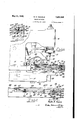
- Fig. 1 is a fragmentary side elevation, partly in section, of a sewing machine, including a workclamping mechanism which embodies the present invention.
- Fig. 2 is an enlarged, fragmentary section through the bed frame of the machinataken sube stantially on the line 2-2 of Fig. 3.
- Fig. 3 is a fragmentary plan view of the Inachine, with the sewing head thereof partly broken" away for better illustration of the work-clamping mechanism underneath.
- Fig. 4 is a perspective view of certain cooperating elements of the work-clamping mechanism
- the present invention is shown as, 1 applied to a button hole sewing machine of 'a. well-known type, comprising a stationary bed frame i5 which carries the work-clamping mechanism hereinafter described, a movable stitch frame or head l6 with the stitching mechanism, and mechanism on the stitch frame for cutting a button hole or the like.
- the stitch frame i6. is
- the stitching mechanism comprises a needle.
- l9f carried-by a needle bar 26, andlooper mechanism.
- I l which may be substantially as shown in the patent to Grip No. ,905,354, April 25, 1933, said, needle bar and saidlooper mechanism being car ried by upper and lower turrets 2i and 2-2, re-"v spectively, which are rotated-in unison at the proper time by gear segments (one being shown at 23 in Fig. 1) that are carried by arock shaft, 25,- operated bythe main cam I in amanneniurther described'in the Reece patents above referred-I to.
- the lower. turret 22 also carries a throat plate 26 through which the needle I9 passes in order to cooperate with the looper mechanism M.
- the needle bar 20 is reciprocated vertically and vibrated laterally in its turret 2
- the looper mechanism I4 is operated in a manner substantially as shown and described in the patent to Grip above referred to and in the patent to Dunnell No. 1,935,083, November 14, 1933.
- the cutting mechanism comprises upper and lower cooperating cutting elements 30 and 3
- the work-clamping mechanism comprises two relatively movable clamps 35 and 35, each consisting of a work-receiving clamp plate 31 and a therewith cooperating clamping foot 38 which is carried by an arm 39, pivotally mounted at 4
- is held in adjusted position by means of a screw 44, projecting through an elongated slot 45 in the block and being threadedly received by its respective clamp plate 31.
- a spacer 46 retains each pivoted arm 39 in engagement with a shoulder 41 of its respective supporting block 4
- the clamp plates 31 are slidably supported on the upper machined surface 50 of the bed frame l5 which is apertured as indicated in dotted lines at 5
- Each clamp plate 31 carries a matrix 53, having its work-engaging surface 54 knurled or otherwise roughened, the same as the sole of the therewith cooperating clamping foot 38, so that the clamped material therebetween may be more firmly gripped.
- the clamp plates 31 are guided for linear movement at right angles to the longitudinal stitching axis :cz: (Fig. 3). This is accomplished by providing a linkage 56 between each clamp plate 31 and the bed frame l5. As the construction and function of each linkage is the same, only one will be described in detail in connection with the clamp plate 31a.
- each linkage 56 consists of two levers or links 51 and 53 which are pivotally mounted at 59 and 88, respectively, on machined bosses GI and 62, respectively, (Fig. 2) on the underside of the bed frame 15.
- the adjacent ends of the links 51, 58 are floatingly pivotally connected with each other at 63 in the fashion best shown in Fig. 4.
- the other end of the rear link 58 is provided with a roller 64 which projects into a longitudinal groove 65 (Figs. 2 and 3) in the underside of the clamp plate 31a and thus forms a floating pivotal connection 66 between the latter and said rear link.
- the forward end of the front link 51 is floatingly pivotally connected at 10 with a slide 1
- the slide 1 is longitudinally adjustably connected with the clamping plate 31a. by means of a bolt 13 whose head 13a. is loosely received in a countersunk portion 15a of an elongated slot 15 in the bed frame l5 and fits accurately in a bore 14 in the clamp plate 31a, and whose shank 13b extends through said slot 15 and through an elongated slot 16 in the slide 1
- the shank 13b has a blank portion 130 which fits accurately in a countersunk portion 15a of the elongated slot 16, and the nut 11 is received in another countersunk portion 16b of said slot 16.
- each clamp plate in either direction is under the guidance by its respective linkage 56 by reason of the bolt connection 13 and the floating pivotal connection 66 therebetween, as will be readily understood.
- are so coordinated that both ends of the clamp plate move for all intents and purposes equal amounts on actuation of the respective slide 1
- the present work-clamping mechanism also provides inner-limit stops which difier, however, fundamentally from those of Kiewicz in that they are simultaneously adjustable on manipulation of a single element and, hence, overcome the previously mentioned disadvantages of the independently adjustable inner-limit stops.
- the innerlimit stops of the present work-clamping mechanism are constituted by the converging surfaces of a wedge member 8I which is located between the opposed slides II. These converging surfaces 80 of the wedge member 8i cooperate with the correspondingly inclined ends 82 of said slides II.
- the wedge member M is provided with a depending lug 33, threadedly receiving at 80 a screw 85 which is rotatably but axially immovably mounted in the depending skirt 86 of the bed frame I5.
- the screw 05 and its head 88 are freely rotatable in a hole 81 and a counter-bore 89, respectively, in said skirt 86, while an adjustable collar 90 prevents, in conjunction vvith the screw head 38, axial movement of said screw 85.
- an adjustable collar 90 prevents, in conjunction vvith the screw head 38, axial movement of said screw 85.
- the slides II are normally yieldingly urged into engagement with their respective stopping surfaces 80 by a tension spring 95, the opposite ends of which are anchored on depending pins 95 on said slides.
- the clamp plates 37 are also normally yieldingly urged into their inner limit positions which are determined by the adjusted wedge member 8!, as will be readily understood.
- a rocker I05 which is pivotally mounted at I06 on the underside of the bed frame I5 and provided with two arms (one being shown at I01) that terminate in fingers I08, each projecting which is adapted to engage followers H2 on the underside of the clamp plates 31 and force the latter outwardly away from each other into. a maximum separated position against the tendency of the spring-urged linkages 56 to force said clamp plates toward each other. :Thisis accomplished after the material or work W- is clamped and when the stitch frame I6, and with it the spreader block III, is moved by the feed.- mechanismfrom the cutting position shownin Figs. 1 and 3 into the stitching position, i. e., to w the left as viewed in Figs. 1 and 3. The result is a tensioning or spreading of the clamped material the extent of which is determined by the adjustment of the wedge member 8
- a bed In a sewing machine, the combination of a bed; two work clamps guided for movement to and from each other on top of said bed and having projections depending below said bed; a manually rotatable and axially immovable screw below the top of the bed and extending transversely to the direction of the clamp movement; and a non-rotatable cam below the bed between and engageable by said projections, said screw being threadedly received by said cam wherefore the limit of the approach of the clamps toward each other may be varied by causing movement of the cam on rotating said screw.
- a bed two work clamps movable on said bed; a linkage so connecting each clamp with the bed as to guide its respective clamp for movement to and from the other clamp; a stop for and engageable by each linkage to prevent movement of the clamps only beyond a predetermined limit of approach to each other; and means including a manually operable single member immovable in the direction of the clamp movement for adjusting said stops simultaneously on manipulation of said member to vary the vapproach limit of the clamps.
Landscapes
- Engineering & Computer Science (AREA)
- Textile Engineering (AREA)
- Sewing Machines And Sewing (AREA)
Priority Applications (4)
| Application Number | Priority Date | Filing Date | Title |
|---|---|---|---|
| US272780A US2201449A (en) | 1939-05-10 | 1939-05-10 | Sewing machine |
| GB17994/39A GB530277A (en) | 1939-05-10 | 1939-06-20 | Improvements in or relating to sewing machines |
| DEI65097D DE712191C (de) | 1939-05-10 | 1939-07-11 | Naehmaschine mit zwei das Werkstueck einspannenden Andruckklemmen |
| FR857749D FR857749A (fr) | 1939-05-10 | 1939-07-12 | Perfectionnements aux machines à coudre |
Applications Claiming Priority (4)
| Application Number | Priority Date | Filing Date | Title |
|---|---|---|---|
| US272780A US2201449A (en) | 1939-05-10 | 1939-05-10 | Sewing machine |
| GB17994/39A GB530277A (en) | 1939-05-10 | 1939-06-20 | Improvements in or relating to sewing machines |
| DEI65097D DE712191C (de) | 1939-05-10 | 1939-07-11 | Naehmaschine mit zwei das Werkstueck einspannenden Andruckklemmen |
| FR857749T | 1939-07-12 |
Publications (1)
| Publication Number | Publication Date |
|---|---|
| US2201449A true US2201449A (en) | 1940-05-21 |
Family
ID=42235910
Family Applications (1)
| Application Number | Title | Priority Date | Filing Date |
|---|---|---|---|
| US272780A Expired - Lifetime US2201449A (en) | 1939-05-10 | 1939-05-10 | Sewing machine |
Country Status (4)
| Country | Link |
|---|---|
| US (1) | US2201449A (de) |
| DE (1) | DE712191C (de) |
| FR (1) | FR857749A (de) |
| GB (1) | GB530277A (de) |
-
1939
- 1939-05-10 US US272780A patent/US2201449A/en not_active Expired - Lifetime
- 1939-06-20 GB GB17994/39A patent/GB530277A/en not_active Expired
- 1939-07-11 DE DEI65097D patent/DE712191C/de not_active Expired
- 1939-07-12 FR FR857749D patent/FR857749A/fr not_active Expired
Also Published As
| Publication number | Publication date |
|---|---|
| FR857749A (fr) | 1940-09-26 |
| GB530277A (en) | 1940-12-09 |
| DE712191C (de) | 1941-10-14 |
Similar Documents
| Publication | Publication Date | Title |
|---|---|---|
| US2201449A (en) | Sewing machine | |
| US1537155A (en) | Tacking and barring machine | |
| US3747544A (en) | Sewing machine with improved binder-feed arrangement | |
| US2151346A (en) | Sewing machine | |
| US1998885A (en) | Presser foot, work holder, and actuating means therefor for sewing machines | |
| US1650588A (en) | Work-clamping mechanism for sewing machines | |
| US1358847A (en) | Sewing-machine | |
| US1839305A (en) | Buttonhole sewing machine | |
| US2346241A (en) | Work clamping mechanism | |
| US1749529A (en) | Presser-foot mechanism for sewing machines | |
| US1428598A (en) | Work-spacing mechanism in buttonhole-sewing machines | |
| US1197639A (en) | Work-clamp. | |
| US3911838A (en) | Automatic apparatus for making piped or welted pockets | |
| US1963933A (en) | Work-guiding and trimming device for sewing machines | |
| US2292432A (en) | Sewing machine | |
| US766833A (en) | Machine for sewing on buttons. | |
| US1785412A (en) | Label-sewing machine | |
| US3082716A (en) | Sewing machines attachment for the sewing of resilient workpieces | |
| US2268367A (en) | Stretching work clamp for sewing machines | |
| US1592916A (en) | Work-gauging means for sewing machines | |
| US2652014A (en) | Sewing machine for stitching leather cases | |
| US1726153A (en) | Buttonhole-sewing machine | |
| US1739244A (en) | Feed mechanism for sewing machines | |
| US1263445A (en) | Welt-shoe-sewing mschine. | |
| US2144763A (en) | Work clamping mechanism for sewing machines |