US2201218A - Machine for grinding noncircular work - Google Patents
Machine for grinding noncircular work Download PDFInfo
- Publication number
- US2201218A US2201218A US46168A US4616835A US2201218A US 2201218 A US2201218 A US 2201218A US 46168 A US46168 A US 46168A US 4616835 A US4616835 A US 4616835A US 2201218 A US2201218 A US 2201218A
- Authority
- US
- United States
- Prior art keywords
- work
- grinding
- machine
- valve
- movement
- Prior art date
- Legal status (The legal status is an assumption and is not a legal conclusion. Google has not performed a legal analysis and makes no representation as to the accuracy of the status listed.)
- Expired - Lifetime
Links
- 230000007246 mechanism Effects 0.000 description 62
- 239000012530 fluid Substances 0.000 description 19
- 238000004513 sizing Methods 0.000 description 15
- 230000002441 reversible effect Effects 0.000 description 6
- QSHDDOUJBYECFT-UHFFFAOYSA-N mercury Chemical compound [Hg] QSHDDOUJBYECFT-UHFFFAOYSA-N 0.000 description 4
- 229910052753 mercury Inorganic materials 0.000 description 4
- 241000282472 Canis lupus familiaris Species 0.000 description 3
- 230000000694 effects Effects 0.000 description 2
- 230000000977 initiatory effect Effects 0.000 description 2
- 238000009877 rendering Methods 0.000 description 2
- 238000010276 construction Methods 0.000 description 1
- 230000007423 decrease Effects 0.000 description 1
- 229910003460 diamond Inorganic materials 0.000 description 1
- 239000010432 diamond Substances 0.000 description 1
- 230000005484 gravity Effects 0.000 description 1
- 238000000034 method Methods 0.000 description 1
- 230000000979 retarding effect Effects 0.000 description 1
Images


Classifications
-
- B—PERFORMING OPERATIONS; TRANSPORTING
- B24—GRINDING; POLISHING
- B24B—MACHINES, DEVICES, OR PROCESSES FOR GRINDING OR POLISHING; DRESSING OR CONDITIONING OF ABRADING SURFACES; FEEDING OF GRINDING, POLISHING, OR LAPPING AGENTS
- B24B19/00—Single-purpose machines or devices for particular grinding operations not covered by any other main group
- B24B19/08—Single-purpose machines or devices for particular grinding operations not covered by any other main group for grinding non-circular cross-sections, e.g. shafts of elliptical or polygonal cross-section
- B24B19/10—Single-purpose machines or devices for particular grinding operations not covered by any other main group for grinding non-circular cross-sections, e.g. shafts of elliptical or polygonal cross-section for grinding pistons
Definitions
- Our invention relates to grinding machines and particularly to the machines for grinding noncylindrical work.
- a further object is to provide a sizing device which may be used on noncylindrical work.
- a further object is to provide means to stop the grinding operation when the work reaches a predetermined size and with the wheel and work in a predetermined relative axial position.
- a further object is to provide novel means for delaying the action of the reversing valve after it has been actuated by a dog on a work table.
- a further object is to provide means to render said delaying means ineffective.
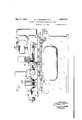
- Figure 1 is a front elevation of our machine.
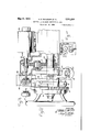
- Figure 2 is a partial end elevation of the wheel feed mechanism.
- Figures 3 and 4 are end and front elevations, respectively of the cutout switch for the feed back off motor.
- Figure 5 is a front elevation of that portion of the automatic feed mechanism mounted on or near the hand wheel.
- Figure 6 is a sectional front elevation of the piston which actuates the feed mechanism.
- Figure 7 is a front elevation of the tarry mechanism and a portion of the reversing valve showing the relation between these two parts.
- Figure 8 is a sectional front elevation of the tarry mechanism.
- Figure 9 is a sectional plan view on line 9-9 of Figure 8.
- Figure 10 is a sectional end elevation of the throttle valve in the tarry mechanism.
- Figure 11 is a front elevation of a portion of the manometer tube showing in imaginary lines the increments of movement of the mercury column.
- Figure 12 is a partial view of the grinding wheel and a work piece, the imaginary lines on the work piece showing increments of change in size corresponding to the above mentioned increments of movement in the mercury column,
- Figure 13 is a front elevation of the sizing device.
- Figure 14 is an end elevation of the sizing device.
- Figures 15 and 16 show type of noncylindrical a contours which may be sized with the sizing device.
- Figure 17 is a plan view of the sizing device showing the relation of the feelers and the nozzle with the work piece, and Ila another arrangement of the sameparts.
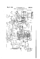
- Figure 18 is a diagrammatic piping and wiring layout.
- the traverse mechanism on our machine is similar to that shown in the copending application 524,706; now Patent Number 2,103,808 dated December 28, 1937.
- the headstock and foot stock are mounted on acradle which is rocked toward and from the wheel by a master cam in a manner similar to that disclosed in copending application 384,068, now'Patent 2,017,927 dated October 22, 1935. Because of the disclosure in the copending applications a description of these structures will not be repeated here.
- the reversing mechanism is retarded in functioning by a tarry mechanism consisting of a pair of pistons reciprocably mounted in a cylinder and adapted to be reciprocated therein by the reversing mechanism. Movement of the pistons is. obstructed by a body of fluid which is forced out of the cylinder and thru a variable restriction. After a predetermined movement of the piston the pressure is released so that the piston and the reversing mechanism are shifted rapidly thru the remainder of the stroke.
- Our machine is designed for grinding work having a noncylindrical contour, particularly oval or elliptical shaped pistons, cams and the like.
- the work is rocked toward and from and is traversed past the grinding wheel which is fed intermittently at one or both ends of the stroke of the work carriage until the work has been ground to size'when the work carriage moves to one end 'Ofits stroke and completes an electrical circuit originated by the sizing device to start a small electric motor which reverses the direction of rotation of the hand wheel shaft and backs the wheel oif sufficiently to permit the removal of the finished work and insert a new piece.
- the amount of rotation of this motor is limited by a switch which is operated by the rotation of the motor to break the circuit thereto.
- the sizing device incorporates a feeler which is adapted to .ride on a surface adjacent the work piece and corresponding in shape to the finished work.
- An air nozzle is mounted to move with the feeler in such a position that the flow of air therefrom is directed toward the work piece.
- Back-017 mechanism Mechanism for backing the grinding wheel away from the work consists of an'electric motor 39 mounted on the housing of the hand wheel shaft. Gear 4
- a work piece W in this case a piston having a noncylindrical skirt is mounted between centers on a rocking support or cradle l0 which in turn is mounted on a work carriage I I, in a manner similar to that disclosed for a cam shaft in the above mentioned Patent No. 2,017,929.
- Said cradle may be rocked toward or from operative position by a piston 2
- a grinding wheel i3 is rotatably mounted on a wheel base I4 which in turn is slidably mounted on said base l2, and movable transversely of the work carriage toward and from the work piece.
- the mechanism for moving the wheel toward and from the work is of the well known pawl and ratchet type working in conjunction with the hand wheel H5.
- the hand wheel i5 is automatically actuated to feed the wheel base toward the work by means of a pawl l6 and aratchet H.
- Said pawl and ratchet may be operated at either or both ends of the carriage reciprocation-by mechanism disclosed diagrammatically in Figure 18 and described in detail in the above mentioned copending application 524,706.
- This portion of the automatic feeding mechanism which is mounted on or adjacent the hand wheel assembly consists briefly of a cylinder l8 in which is mounted the piston l9 movable in one direction by fluid under pressure and in the opposite direction by a spring 20 which is mounted on a tail road 2! of piston I9.
- a piston rod 22 carries an element 23 to which is attached one end of a bell crank 24.
- the other end of the bell crank is a gear segment 25 which meshes with another gear segment 28 mounted on hand wheel shaft 271.
- a pawl arm'28 forms a projection of said-segment 26 and pawl 16 is mounted on the end of said arm and held in engagement with ratchet ll by means of a spring I 8.
- a shield 29 covering a portion of the teeth on said ratchet wheel is attached to an element 30 which is rotatably mounted on hand wheel sheft 21.
- Pawl arm 28 is normally held in inoperative position by means of spring 28' attached to another portion, of the element of which arm 28 forms a part. In this position pawl I6 is drawn back of shield 29 and thus held out of engagement with the teeth of ratchet ll.
- extending from said element 30 at another point is attached by a link 32 to the armature 33 of a solenoid 36.
- An adjustable stop 35 is mounted on the hand wheel and adapted to engage a removably mounted stop 36.
- Said stop 36 is attached to an armature 31 of solenoid 38, said solenoid being effective to withdraw stop 36 from operative position.
- Stop 36 may be held in operative position by any suitable means such as by gravity or by a spring not shown.
- the tarry mechanism This mechanism is attached directly to a reversing valve 60 by means of a bracket 6! adjustably mounted therein and adapted to be locked in adjusted position.
- Link 62 connects said bracket with a lever 63 pivoted at 64 in a housing 65 which contains the operating parts of the tarry mechanism.
- the principal working element of said mechanism is a pair of pistons 66 and 61 joined by reduced portion 68 to which is attached the other end of lever'63.
- Each of said pistons has a hole extending axially into the piston from the ends; and from this hole extends several smaller radial passages opening into a groove in the peripherial surface of the piston.
- the purpose of this construction is to provide for retarding the initial movement of the reversing valve and thenpermit a quick movement to reverse position as said passages line up with ports H or it and permit fluid to be released.
- Said pistons are adapted to be reciprocated in a cylindrical bore 89 in housing 65.
- the fluid passage i0 connects opposite ends of said bore but the movement of fluid through said passage is not sufiicient to open them. However, if the operator desires to shift the reversing lever manually and rapidly, pressure on the fluid will be sufiicient to open the valve and permit the fluid to pass from one side of the bore to the other without going through the throttle valve H.
- a fluid reservoir l6 connected to bore 69 by ports'ii and i8.
- Reversing lever i9 is adjustably connected to valve 50 by rod 80, one end of which is headed and adapted to be inserted in the hollow end of said valve 60. Hollow plug 8!
- a movement of the reversing valve is completed by means of the well knownsnap action mechanism consisting of a sp g pressed pl r 8 chgaging roller 86 on the end of reversing lever 19.
- Sizing device The sizing device used on this machine is shown in Figures 11 to 1'7 inclusive.
- the method of sizing consists in utilizing a master surface or pattern which is identical in shape with the finished work piece.
- the master surface or pattem' 90 is axially aligned with the work piece W and forms a part of the driving mechanism therefore.
- supported on a bracket 92 rides on the work piece W during the preliminary grinding operation. Adjacent said" shoe and in the same bracket is a nozzle 93 directed against the work piece. Adjacent said nozzle and adapted to engage the master surface is a diamond pointed fee1er'94 mounted in a holder 95 which is adjustable toward and from said master surface or pattern independently of the pressure which is at valve als used in Fig. 17 apply to corresponding parts in Fig. 11a.
- W indicates-the work piece numeral 30 a pattern, 33 a nozzle directed against the surface of said pattern, and 34 a feel'er engaging the surface of work W.
- the space between the nozzle and the pattern decreases as the work is ground to size.
- Both the bracket 32 and the holder 36 are mounted on bracket 36, which in turn is pivotally mounted at 31 to another bracket 33 secured to the work carriage or cradle I0.
- the feelers are held in operative relation to the work by means of a spring 33 and a stud 31.
- the handle I may be used to move the device toward or from operative position.
- the device may be held in inoperative position by means of a rod IOI attached thereto and urged by a spring I02 against the stud I03in which is cut a notch I04.
- Said rod is adapted to drop into said notch when the device is withdrawn from operative position.
- the rod may be withdrawn from the notch by means of a lever I06,
- Piston grinder operation The flow of fluid to the various mechanisms passes thru a main valve body I20 which has been described in the copending application 524,706.
- fluid is supplied by pump I22 thru line I23 to relief valve I24 in said valve body.
- relief valve From said relief valve the fluid passes thru a start and stop valve I2I to reversing valve 60.
- Said reversing valve is actuated by dogs I33 and I33 adjustably mounted on rail I40 on the carriage II and directs the fluid thru passage I26 to cylinder I26.
- valves I26 and I23 are connected by passage I3I in which is placed a throttle valve I31 to control the rate of flow of fluid between said cylinders and hence the rate of movement of the carriage II.
- a throttle valve I31 to control the rate of flow of fluid between said cylinders and hence the rate of movement of the carriage II.
- the operator shifts lever I32 to the left thereby shifting valves I2I and I33 to the right. In this position fluid under I2I is returned to the reservoir thru passage I34 instead of to the reversing valve. Movement of valve I33 to the right connects passages I35 and I36 to form a by pass around valve I31 and so permit the carriage to be traversed manually with a minimum of resistance.
- Cam I, adjustably attached to dog I33 engages roller I42 on lever I44 to supply fluid under 4 I43 to actuate valve pressure to one end of feed cylinder I3.
- Spring I46 normally holds said valve in position to exhaust the fluid from said cylinder.
- cam I60 closes switch I6I to close a circuit from supply line I62 thru line I63 to relay I64. Closing said relay'completes circuits from supply lines I62, I66, I66 to'headstock motor I61 thru lines I63, I63 and I10. A fourth circuit is closed from line I62 thru line HI and stop switch I12 to line I63 thereby providing a holding circuit for relay I64.
- line I63 is tapped by line I30 to which said mechanisms are connected. Either line I62 or line I66 maybe used for the return line. In this case line I62 is used.
- Stop 36 thus serves to facilitate positioning the grinding wheel close to the surface of the work.
- solenoid 33 becomes energized thru lines I30 and I34 and withdraws stop 36 from the path of stop", to permit the operation or rotation of hand wheel I6 during the grinding operation.
- the headstock motor is stopped by shifting lever I32 to the left. Since solenoid 33 depends on the motor circuit it becomes deenergized and stop 36 is permitted to return to a position in the path of stop 35.
- Motor 33 causes a reverse movement of the feed mechanism and at a predetermined point actuates stop switch 61 to break the circuit thereto. Opening said switch also breaks the circuit to solenoid 206 permitting spring 206 to shift valve I23 to its lowermost position in which the connection is broken between fluid lines I21 and I thru,
- a work support means to efiect a relative transverse feeding movement between. said supports, means to effect a relative longitudinal reciprocating movement between said supports, a reversing mechanism in control of said reciprocating movement, additional mechanism separate from said reversing mechanism and operable in response to a change in size of a work piece for rendering said reversing mechanism inefiective to continue said longitudinal reciprocating movement.
- a work support a pattern member mounted thereon in axial alignment with a work member, means for changing the size and contour of said work memher to approach the size and contour of said pattern member comprising a grinding wheel mounted thereon, mechanism for effecting a relative feeding movement between said supports, and'a sizing device for controlling said feeding movement including a feeler in contact with one of said members and a nozzle directed against the other.
- a tool support a tool support, mechanisms to effect relative transverse and longitudinal movements of said supports, a reversing mechanism for controlling said longitudinal movement, mechanism separate from said reversing mechanism toprevent the operation of said longitudinal moving means in one direction, a solenoid attached to said last named mechanism, means to reverse said transverse movement to separate the tool and the work and means actuated by said reversing means to control said solenoid.
- a work support a pattern member mounted thereon in axial alignment with a work member, means for changing the size and contour of said work member to approach the size and contour of said pattern member comprising a wheel support, a grinding wheel mounted thereon, mechanism for effecting a relative feeding movement between said supports and a'sizing device by controlling said feeding movement, including a feeler in contact with one of said elements and a nozzle directed against the other and means to maintain a fixed relation between said nozzle and the surface against which .it is directed until the work reaches a predetermined size.
- a work support a pattern member mounted thereon in axial alignment with a work member, means for changing the size and contour of said work member to approach the size and contour of said pattern member coinprising a wheel support, a
- mechanism for- ,e'ifecting a relative feeding movement between said supports and a sizing device by controlling said feeding movement including a feeler in contact with one of said elements and a nozzle directed against the other, means to maintain a ter cam and roller to move the grinding wheel and work support relatively toward and from each other duringthe grinding operation to grind a cam blank to a predetermined contour, a sizing device including a movable feeler which continuously engages the periphery of the cam being ground during grinding automatically to control said feeding mechanism, and means to automatically move the sizing head into an operative position so that the contactmember engages the periphery of the cam being ground.
- a cam grinding machine of the type having a rotatable camshaft support which is rocked toward and from a rotatable grinding wheel by means of a master cam and a follower, a rotatable support for said wheel, a reversible feeding mechanism to cause a relative transverse feeding movement between the grinding wheel and the cam being ground to grind the same to a predetermined size and contour, a size controlling apparatus including a movable contact member which engages the periphery of the cam being ground, and means responsive when said contact member reaches a predetermined position to reverse said feeding mechanism to separate the cam and the grinding wheel.
- a manually operated feeding mechanism comprising a hand wheeel, a positive.
- a work support a tool support, mechanisms to efiect relative transverse and longitudinal movements of said supports, a reversing mechanism for controlling said longitudinal movement, mechanism separate from said reversing mechanism to prevent the operation of said longitudinal moving means in one direction, actuating means attached to said last named mechanism, means to reverse said transverse movement to separate the tool and the work and means actuated by said reversing means to control said actuating means.
- a work support a tool support, mechanisms for efiecting relative transverse and longitudinal movements ofsaid supports, a size control mechanism for controlling said transverse movement and means operable thereby in response to a predetermined change in size of a work piece for initiating said transverse movement in a direction to separate the tool and work, means operable by said separating means to stop said transverse movement and means controlled by said stopping means for preventing further operation of said longitudinal moving mechanism.
- a work support a tool support, mechanisms for effecting relative transverse and longitudinal movements of said supports, means for controlling said longitudinal movement including a reversing mechanism, control means separate from said reversing mechanism for effecting operation of said longitudinal moving mechanism in one direction, means for initiating operation of said transverse moving mechanism for feeding said tool toward said work, additional mechanism for separating the tool and work and means responsive to operation of said additional mechanism for rendering said reversing mechanism inoperative and for effecting said longitudinal movement in one direction.
Landscapes
- Engineering & Computer Science (AREA)
- Mechanical Engineering (AREA)
- Constituent Portions Of Griding Lathes, Driving, Sensing And Control (AREA)
Description
y 21, 1940- H. E. BALSIGER El AL 2,201,218
MACHINE FOR GRINDING NONCIRGULAR WORK Filed Oct. 22, 1935 7 Sheets-Sheet 1 2 Q19 7 we INVENTORS. #1492020 asnwlqaa BYCOMEZAD L. 077'.
from
1940. H. E. BALSIGER ET m. 2,201,218
MACHINE FOR GRINDING NONCIRCULAR WdRK Filed Oct. 22, 1935 7 Sheets-Sheet 2 I III I a i. mm|m I", k II INVENTORS I I I M/weow E. ems/cm.
sow/e00 1. arr.
A TTORNE Y May 21, 1940. H. E. BALSIGER Er AL 2,201,218
MACHINE FOR GRINDING NONCIRCULAR WORK Filed 001;. 22, 1935 7 Sheets-Sheet 3 .INVENTQRS HflROLD LBQLSIGER.
v CON/29D 1.. OTT. V
A ORNEY H. E. BALSIGER El AL momma FOR GRINDING NONCIRCULAR wonx Filed Oct. 22, 1955 May 21, 1940.
7' Sheets-Sheet 4 BY /A X/7 42% A TTORNEY May 21, 1940. H. E. BALSIGER El AL MACHINE FOR GRINDING NONCIRCULAR WORK Fild Oct. 22, 1935 7 Sheets-Sheet 5 "INVENTORJ. HH/EOLD 5.
GOA E90 M ATTORNEY v May 21, 1940. H. E. BALSIGER El AL MACHINE FOR GRINDING NONCIRCULAR WORK '7 Sheets-Sheet 6 Filed Oct. 22, 1935 INVENTORS mean [2.861316% coN/Eao 1.. arr.
ATTORNEY May 21, 1940.
' H. E. BALSIGER ET AL MACHINE FOR GRINDING NONCIRCULA R WORK Filed 001;. 22, 1955 7 SheetsSheet 7 INVENTORS GOA/E00 L. 077:
ATTORNEY Patented May 21,1940
UNITED STATES FOR GRINDING NONCIROULAR WORK Harold E. Balsiger and Conrad L. Ott, Waynesboro, Pa, assignors to Landis Tool Company, Waynesboro, Pa., a corporation of Pennsylvania Application October 22, 1935, Serial No.46,168
11 Claims.
Our invention relates to grinding machines and particularly to the machines for grinding noncylindrical work.
It is an object of our invention to provide a machine in which elliptical or other noncylindrical shapes may be ground automatically to a predetermined size.
A further object is to provide a sizing device which may be used on noncylindrical work.
A further object is to provide means to stop the grinding operation when the work reaches a predetermined size and with the wheel and work in a predetermined relative axial position.
A further object is to provide novel means for delaying the action of the reversing valve after it has been actuated by a dog on a work table.
A further object is to provide means to render said delaying means ineffective.
In the drawings Figure 1 is a front elevation of our machine.
Figure 2 is a partial end elevation of the wheel feed mechanism.
Figures 3 and 4 are end and front elevations, respectively of the cutout switch for the feed back off motor.
Figure 5 is a front elevation of that portion of the automatic feed mechanism mounted on or near the hand wheel.
Figure 6 is a sectional front elevation of the piston which actuates the feed mechanism.
Figure 7 is a front elevation of the tarry mechanism and a portion of the reversing valve showing the relation between these two parts.
Figure 8 is a sectional front elevation of the tarry mechanism.
Figure 9 is a sectional plan view on line 9-9 of Figure 8.
Figure 10 is a sectional end elevation of the throttle valve in the tarry mechanism.
Figure 11 is a front elevation of a portion of the manometer tube showing in imaginary lines the increments of movement of the mercury column.
Figure 12 is a partial view of the grinding wheel and a work piece, the imaginary lines on the work piece showing increments of change in size corresponding to the above mentioned increments of movement in the mercury column,
Figure 13 is a front elevation of the sizing device.
Figure 14 is an end elevation of the sizing device.
Figures 15 and 16 show type of noncylindrical a contours which may be sized with the sizing device. I
Figure 17 is a plan view of the sizing device showing the relation of the feelers and the nozzle with the work piece, and Ila another arrangement of the sameparts.
Figure 18 is a diagrammatic piping and wiring layout.
The traverse mechanism on our machine is similar to that shown in the copending application 524,706; now Patent Number 2,103,808 dated December 28, 1937. The headstock and foot stock are mounted on acradle which is rocked toward and from the wheel by a master cam in a manner similar to that disclosed in copending application 384,068, now'Patent 2,017,927 dated October 22, 1935. Because of the disclosure in the copending applications a description of these structures will not be repeated here.
The reversing mechanism is retarded in functioning by a tarry mechanism consisting of a pair of pistons reciprocably mounted in a cylinder and adapted to be reciprocated therein by the reversing mechanism. Movement of the pistons is. obstructed by a body of fluid which is forced out of the cylinder and thru a variable restriction. After a predetermined movement of the piston the pressure is released so that the piston and the reversing mechanism are shifted rapidly thru the remainder of the stroke.
Our machine is designed for grinding work having a noncylindrical contour, particularly oval or elliptical shaped pistons, cams and the like. The work is rocked toward and from and is traversed past the grinding wheel which is fed intermittently at one or both ends of the stroke of the work carriage until the work has been ground to size'when the work carriage moves to one end 'Ofits stroke and completes an electrical circuit originated by the sizing device to start a small electric motor which reverses the direction of rotation of the hand wheel shaft and backs the wheel oif sufficiently to permit the removal of the finished work and insert a new piece. The amount of rotation of this motor is limited by a switch which is operated by the rotation of the motor to break the circuit thereto. At the same time the work cradle is rocked to inoperative position by a hydraulic motor. The sizing device incorporates a feeler which is adapted to .ride on a surface adjacent the work piece and corresponding in shape to the finished work. An air nozzle is mounted to move with the feeler in such a position that the flow of air therefrom is directed toward the work piece.
Back-017 mechanism Mechanism for backing the grinding wheel away from the work consists of an'electric motor 39 mounted on the housing of the hand wheel shaft. Gear 4| is mounted on the end of the' shaft 80. Said switch consists of a friction operated disc $5 on whichis mounted 2. lug d6. Said lug 46 is adapted to engage a lug 41 on strip 48, which in'atum is attached to an arm 49 rotatable about a pivot 50. Said strip 38 is attached loosely at another point 5i. to arm 52 pivoted at 53. On one end of said arm 52 is a pair of contacts 55 which are normally held in engagement with terminals 56 by means of a spring 53 acting against said arm 52.
A work piece W, in this case a piston having a noncylindrical skirt is mounted between centers on a rocking support or cradle l0 which in turn is mounted on a work carriage I I, in a manner similar to that disclosed for a cam shaft in the above mentioned Patent No. 2,017,929. Said cradle may be rocked toward or from operative position by a piston 2| 9 in cylinder 2! E, Figure 18.
.Fluid under pressure is directed to opposite ends of said cylinder by valve E23. Said carriage may be reciprocated on said base by a hydraulic mechanism disclosed diagrammatically in Figure 18 and described in detail in the above mentioned copending application 524,706.
A grinding wheel i3 is rotatably mounted on a wheel base I4 which in turn is slidably mounted on said base l2, and movable transversely of the work carriage toward and from the work piece. The mechanism for moving the wheel toward and from the work is of the well known pawl and ratchet type working in conjunction with the hand wheel H5.
The hand wheel i5 is automatically actuated to feed the wheel base toward the work by means of a pawl l6 and aratchet H. Said pawl and ratchet may be operated at either or both ends of the carriage reciprocation-by mechanism disclosed diagrammatically in Figure 18 and described in detail in the above mentioned copending application 524,706. This portion of the automatic feeding mechanism which is mounted on or adjacent the hand wheel assembly consists briefly of a cylinder l8 in which is mounted the piston l9 movable in one direction by fluid under pressure and in the opposite direction by a spring 20 which is mounted on a tail road 2! of piston I9. A piston rod 22 carries an element 23 to which is attached one end of a bell crank 24. The other end of the bell crank is a gear segment 25 which meshes with another gear segment 28 mounted on hand wheel shaft 271. A pawl arm'28 forms a projection of said-segment 26 and pawl 16 is mounted on the end of said arm and held in engagement with ratchet ll by means of a spring I 8. A shield 29 covering a portion of the teeth on said ratchet wheel is attached to an element 30 which is rotatably mounted on hand wheel sheft 21. Pawl arm 28 is normally held in inoperative position by means of spring 28' attached to another portion, of the element of which arm 28 forms a part. In this position pawl I6 is drawn back of shield 29 and thus held out of engagement with the teeth of ratchet ll. An arm 3| extending from said element 30 at another point is attached by a link 32 to the armature 33 of a solenoid 36. An adjustable stop 35 is mounted on the hand wheel and adapted to engage a removably mounted stop 36. Said stop 36 is attached to an armature 31 of solenoid 38, said solenoid being effective to withdraw stop 36 from operative position. Stop 36 may be held in operative position by any suitable means such as by gravity or by a spring not shown. The soleinto the circuit on motor I67.
The tarry mechanism This mechanism is attached directly to a reversing valve 60 by means of a bracket 6! adjustably mounted therein and adapted to be locked in adjusted position. Link 62 connects said bracket with a lever 63 pivoted at 64 in a housing 65 which contains the operating parts of the tarry mechanism. The principal working element of said mechanism is a pair of pistons 66 and 61 joined by reduced portion 68 to which is attached the other end of lever'63. Each of said pistons has a hole extending axially into the piston from the ends; and from this hole extends several smaller radial passages opening into a groove in the peripherial surface of the piston. The purpose of this construction is to provide for retarding the initial movement of the reversing valve and thenpermit a quick movement to reverse position as said passages line up with ports H or it and permit fluid to be released.
Said pistons are adapted to be reciprocated in a cylindrical bore 89 in housing 65. The fluid passage i0 connects opposite ends of said bore but the movement of fluid through said passage is not sufiicient to open them. However, if the operator desires to shift the reversing lever manually and rapidly, pressure on the fluid will be sufiicient to open the valve and permit the fluid to pass from one side of the bore to the other without going through the throttle valve H. In the upper portion of the housing 65 is a fluid reservoir l6 connected to bore 69 by ports'ii and i8. Reversing lever i9 is adjustably connected to valve 50 by rod 80, one end of which is headed and adapted to be inserted in the hollow end of said valve 60. Hollow plug 8! is threaded into the end of said valve and prevents said rod from being withdrawn from said valve. A nut 82 is threaded on said rod and the distance between the nut and the head on said rod is the amount of lost motion permitted in the operation of the reversing valve. This of course is adjustable. A movement of the reversing valve is completed by means of the well knownsnap action mechanism consisting of a sp g pressed pl r 8 chgaging roller 86 on the end of reversing lever 19.
Sizing device The sizing device used on this machine is shown in Figures 11 to 1'7 inclusive.
The method of sizing consists in utilizing a master surface or pattern which is identical in shape with the finished work piece. In this 'particular case the master surface or pattem' 90 is axially aligned with the work piece W and forms a part of the driving mechanism therefore. An adjustable shoe 9| supported on a bracket 92 rides on the work piece W during the preliminary grinding operation. Adjacent said" shoe and in the same bracket is a nozzle 93 directed against the work piece. Adjacent said nozzle and adapted to engage the master surface is a diamond pointed fee1er'94 mounted in a holder 95 which is adjustable toward and from said master surface or pattern independently of the pressure which is at valve als used in Fig. 17 apply to corresponding parts in Fig. 11a. W indicates-the work piece numeral 30 a pattern, 33 a nozzle directed against the surface of said pattern, and 34 a feel'er engaging the surface of work W. In this case the space between the nozzle and the pattern decreases as the work is ground to size. Both the bracket 32 and the holder 36 are mounted on bracket 36, which in turn is pivotally mounted at 31 to another bracket 33 secured to the work carriage or cradle I0. The feelers are held in operative relation to the work by means of a spring 33 and a stud 31. The handle I may be used to move the device toward or from operative position. The device may be held in inoperative position by means of a rod IOI attached thereto and urged by a spring I02 against the stud I03in which is cut a notch I04. Said rod is adapted to drop into said notch when the device is withdrawn from operative position. The rod may be withdrawn from the notch by means of a lever I06,
one end of which'engages a collar I05 on the" rod IN. I
Piston grinder operation The flow of fluid to the various mechanisms passes thru a main valve body I20 which has been described in the copending application 524,706. In the normal operation of the machine fluid is supplied by pump I22 thru line I23 to relief valve I24 in said valve body. From said relief valve the fluid passes thru a start and stop valve I2I to reversing valve 60. Said reversing valve is actuated by dogs I33 and I33 adjustably mounted on rail I40 on the carriage II and directs the fluid thru passage I26 to cylinder I26.
or thru passage I21 to valve I23 and passage I30 to cylinder I23. As described in the copending application 524,706 cylinders I26 and I23 are connected by passage I3I in which is placed a throttle valve I31 to control the rate of flow of fluid between said cylinders and hence the rate of movement of the carriage II. To stop the traverse mechanism the operator shifts lever I32 to the left thereby shifting valves I2I and I33 to the right. In this position fluid under I2I is returned to the reservoir thru passage I34 instead of to the reversing valve. Movement of valve I33 to the right connects passages I35 and I36 to form a by pass around valve I31 and so permit the carriage to be traversed manually with a minimum of resistance. Cam I, adjustably attached to dog I33 engages roller I42 on lever I44 to supply fluid under 4 I43 to actuate valve pressure to one end of feed cylinder I3. Spring I46 normally holds said valve in position to exhaust the fluid from said cylinder.
When lever I32 is shifted to the right, cam I60 closes switch I6I to close a circuit from supply line I62 thru line I63 to relay I64. Closing said relay'completes circuits from supply lines I62, I66, I66 to'headstock motor I61 thru lines I63, I63 and I10. A fourth circuit is closed from line I62 thru line HI and stop switch I12 to line I63 thereby providing a holding circuit for relay I64. To provide current for the various mechanisms onthe machine, line I63 is tapped by line I30 to which said mechanisms are connected. Either line I62 or line I66 maybe used for the return line. In this case line I62 is used.
To bring the grinding wheel rapidly into contact with the work the operator turns the hand wheel I6 until adjustable stop 36, mounted thereon, engages the removable stop 36. Stop 36 thus serves to facilitate positioning the grinding wheel close to the surface of the work. As soon as the headstock motor I61 is started by shifting lever I32 to close switch I6I, solenoid 33 becomes energized thru lines I30 and I34 and withdraws stop 36 from the path of stop", to permit the operation or rotation of hand wheel I6 during the grinding operation. After the completion of the grinding operation when the hand wheel has been automatically reversed-the headstock motor is stopped by shifting lever I32 to the left. Since solenoid 33 depends on the motor circuit it becomes deenergized and stop 36 is permitted to return to a position in the path of stop 35.
when the rough grinding operation is completed the mercury in tube I46 will complete a circuit between contacts I41 and I43 to close relay I60. This closes a circuit from line I30 thru solenoid 34, then thru line I3I to line I62- However the supply from line I62 to contacts I41 is available only when the carriage is at the extreme left hand position when adjustable cam the'mercury engages contact I43 .Part of the circuit is closed thru line I32 to relay I33 and thence thru line I30. Contact I41 remains dead until the circuit from line I62 thereto is completed when cam 200 on the carriage II closes switch 203. Relay I33 is thus closed permitting current to pass to motor 33 and back thru line 204 and stop switch 61 to line I62. Motor 33 causes a reverse movement of the feed mechanism and at a predetermined point actuates stop switch 61 to break the circuit thereto. Opening said switch also breaks the circuit to solenoid 206 permitting spring 206 to shift valve I23 to its lowermost position in which the connection is broken between fluid lines I21 and I thru,
ment but since. fluid cannot reach the motor due to the position of valve I23 the carriage remains motionless in its left hand position where finished work may be removed and anew piece placed in the machine.
We claim:
1. In a machine of the kind described, a work support, a tool support, means to efiect a relative transverse feeding movement between. said supports, means to effect a relative longitudinal reciprocating movement between said supports, a reversing mechanism in control of said reciprocating movement, additional mechanism separate from said reversing mechanism and operable in response to a change in size of a work piece for rendering said reversing mechanism inefiective to continue said longitudinal reciprocating movement.
2. In a machine of the kind described a work support, a pattern member mounted thereon in axial alignment with a work member, means for changing the size and contour of said work memher to approach the size and contour of said pattern member comprising a grinding wheel mounted thereon, mechanism for effecting a relative feeding movement between said supports, and'a sizing device for controlling said feeding movement including a feeler in contact with one of said members and a nozzle directed against the other.
3. In a machine of the kind described a work,
support, a tool support, mechanisms to effect relative transverse and longitudinal movements of said supports, a reversing mechanism for controlling said longitudinal movement, mechanism separate from said reversing mechanism toprevent the operation of said longitudinal moving means in one direction, a solenoid attached to said last named mechanism, means to reverse said transverse movement to separate the tool and the work and means actuated by said reversing means to control said solenoid.
4. In a machine of the kind described a work support, a pattern member mounted thereon in axial alignment with a work member, means for changing the size and contour of said work member to approach the size and contour of said pattern member comprising a wheel support, a grinding wheel mounted thereon, mechanism for effecting a relative feeding movement between said supports and a'sizing device by controlling said feeding movement, including a feeler in contact with one of said elements and a nozzle directed against the other and means to maintain a fixed relation between said nozzle and the surface against which .it is directed until the work reaches a predetermined size.
5. In a machine of the kind described a work support, a pattern member mounted thereon in axial alignment with a work member, means for changing the size and contour of said work member to approach the size and contour of said pattern member coinprising a wheel support, a
grinding wheel mounted thereon, mechanism for- ,e'ifecting a relative feeding movement between said supports and a sizing device by controlling said feeding movement, including a feeler in contact with one of said elements and a nozzle directed against the other, means to maintain a ter cam and roller to move the grinding wheel and work support relatively toward and from each other duringthe grinding operation to grind a cam blank to a predetermined contour, a sizing device including a movable feeler which continuously engages the periphery of the cam being ground during grinding automatically to control said feeding mechanism, and means to automatically move the sizing head into an operative position so that the contactmember engages the periphery of the cam being ground.
7. A cam grinding machine of the type having a rotatable camshaft support which is rocked toward and from a rotatable grinding wheel by means of a master cam and a follower, a rotatable support for said wheel, a reversible feeding mechanism to cause a relative transverse feeding movement between the grinding wheel and the cam being ground to grind the same to a predetermined size and contour, a size controlling apparatus including a movable contact member which engages the periphery of the cam being ground, and means responsive when said contact member reaches a predetermined position to reverse said feeding mechanism to separate the cam and the grinding wheel.
mounted thereon, a manually operated feeding mechanism comprising a hand wheeel, a positive.
stop to stop the operation of said hand wheel with the grinding wheel in position to start grinding a work piece, automatic means to actuate said feed mechanism during the grinding operation and additional automatic means operable in response to starting said work rotating means to withdraw said stop whereby to permit said first automatic means to actuate said feed mechanism.
' 9. In a machine of the kind described, a work support, a tool support, mechanisms to efiect relative transverse and longitudinal movements of said supports, a reversing mechanism for controlling said longitudinal movement, mechanism separate from said reversing mechanism to prevent the operation of said longitudinal moving means in one direction, actuating means attached to said last named mechanism, means to reverse said transverse movement to separate the tool and the work and means actuated by said reversing means to control said actuating means.
10. In a grinding machine, a work support, a tool support, mechanisms for efiecting relative transverse and longitudinal movements ofsaid supports, a size control mechanism for controlling said transverse movement and means operable thereby in response to a predetermined change in size of a work piece for initiating said transverse movement in a direction to separate the tool and work, means operable by said separating means to stop said transverse movement and means controlled by said stopping means for preventing further operation of said longitudinal moving mechanism.
11. In a grinding machine, a work support, a tool support, mechanisms for effecting relative transverse and longitudinal movements of said supports, means for controlling said longitudinal movement including a reversing mechanism, control means separate from said reversing mechanism for effecting operation of said longitudinal moving mechanism in one direction, means for initiating operation of said transverse moving mechanism for feeding said tool toward said work, additional mechanism for separating the tool and work and means responsive to operation of said additional mechanism for rendering said reversing mechanism inoperative and for effecting said longitudinal movement in one direction.
HAROLD E. BALSIGER. CONRAD .L. 0'11.
Priority Applications (1)
| Application Number | Priority Date | Filing Date | Title |
|---|---|---|---|
| US46168A US2201218A (en) | 1935-10-22 | 1935-10-22 | Machine for grinding noncircular work |
Applications Claiming Priority (1)
| Application Number | Priority Date | Filing Date | Title |
|---|---|---|---|
| US46168A US2201218A (en) | 1935-10-22 | 1935-10-22 | Machine for grinding noncircular work |
Publications (1)
| Publication Number | Publication Date |
|---|---|
| US2201218A true US2201218A (en) | 1940-05-21 |
Family
ID=21941978
Family Applications (1)
| Application Number | Title | Priority Date | Filing Date |
|---|---|---|---|
| US46168A Expired - Lifetime US2201218A (en) | 1935-10-22 | 1935-10-22 | Machine for grinding noncircular work |
Country Status (1)
| Country | Link |
|---|---|
| US (1) | US2201218A (en) |
Cited By (3)
| Publication number | Priority date | Publication date | Assignee | Title |
|---|---|---|---|---|
| US2603043A (en) * | 1947-07-18 | 1952-07-15 | Sarl Ets Gendron Freres | Gauge controlled grinding wheel feed mechanism |
| US3247619A (en) * | 1963-06-06 | 1966-04-26 | Landis Tool Co | Machine for grinding pistons automatically |
| JPS49118679U (en) * | 1973-02-08 | 1974-10-11 |
-
1935
- 1935-10-22 US US46168A patent/US2201218A/en not_active Expired - Lifetime
Cited By (3)
| Publication number | Priority date | Publication date | Assignee | Title |
|---|---|---|---|---|
| US2603043A (en) * | 1947-07-18 | 1952-07-15 | Sarl Ets Gendron Freres | Gauge controlled grinding wheel feed mechanism |
| US3247619A (en) * | 1963-06-06 | 1966-04-26 | Landis Tool Co | Machine for grinding pistons automatically |
| JPS49118679U (en) * | 1973-02-08 | 1974-10-11 |
Similar Documents
| Publication | Publication Date | Title |
|---|---|---|
| US2429830A (en) | Grinding machine | |
| US2201218A (en) | Machine for grinding noncircular work | |
| US2984952A (en) | Pressure operated feed control for grinding machines | |
| US2192308A (en) | Grinding wheel dresser | |
| US1933373A (en) | Grinding and lapping machine | |
| US2335356A (en) | Grinding machine | |
| US1938762A (en) | Grinding machine | |
| US1805056A (en) | Grinding machine | |
| US2243410A (en) | Cam grinder | |
| US2502862A (en) | Internal grinding machine | |
| US2349786A (en) | Grinding wheel feeding mechanism | |
| US1817180A (en) | Control mechanism for internal grinding machines | |
| US2148337A (en) | Honing machine | |
| US2378903A (en) | Grinding machine | |
| US2248463A (en) | Grinding wheel dressing mechanism | |
| US2328251A (en) | Index mechanism | |
| US2448874A (en) | Hydraulically operated wheel feeding mechanism | |
| US2190132A (en) | Grinding wheel truing apparatus | |
| US2023777A (en) | Feed control | |
| US1952458A (en) | Abrading machine | |
| US1731719A (en) | Grinding machine | |
| US2015414A (en) | Hydraulic indexing mechanism | |
| US2117916A (en) | Automatic cam grinding machine | |
| US2133386A (en) | Gear grinding machine | |
| US1816082A (en) | Grinding machine |