US2193032A - Suction slice for paper making machines - Google Patents
Suction slice for paper making machines Download PDFInfo
- Publication number
- US2193032A US2193032A US120968A US12096837A US2193032A US 2193032 A US2193032 A US 2193032A US 120968 A US120968 A US 120968A US 12096837 A US12096837 A US 12096837A US 2193032 A US2193032 A US 2193032A
- Authority
- US
- United States
- Prior art keywords
- slice
- foam
- suction
- pipe
- stuff
- Prior art date
- Legal status (The legal status is an assumption and is not a legal conclusion. Google has not performed a legal analysis and makes no representation as to the accuracy of the status listed.)
- Expired - Lifetime
Links
Images

Classifications
-
- D—TEXTILES; PAPER
- D21—PAPER-MAKING; PRODUCTION OF CELLULOSE
- D21F—PAPER-MAKING MACHINES; METHODS OF PRODUCING PAPER THEREON
- D21F1/00—Wet end of machines for making continuous webs of paper
Landscapes
- Paper (AREA)
Description
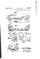
March 12,1940. K, MACKENZlE 2,193,032
SUCTION SLICE FOR PAPER MAKING MACHINES Filed Jan. 16, 1957 2 Sheets-Sheet l Q lhmeilz INV NTORZ A TTORNEYS.
T0 SUCTION PUMP March 12, 1940. K. J. MACKENZIE SUCTION SLICE FOR PAPER MAKING MACHINES 2 Sheets-Sheet 2 Filed Jan. 16, 1957 mm wm V m Patented Mar. 12, 1940 SUCTION SLICE FOB PAPER MAmNG moms Kenneth J. Machenme, Rochester, N. Y., assignor to Eastman Kodak Company, Rochester, N. Y., a. corporation of New Jersey Application January 16, 1937, Serial No, 120,968
4 Clam.
This invention relates to paper making machines and particularly to slices for controlling the flow of stuff in such machines.
One object of my invention is to provide a slice 5 adapted to remove foam which usually occurs near a slice in the wet end of a paper making machine.
of stuff passing through a passageway and at the 10 .same time will also provide an exit for foam acother object of my invention is to provide a slice in the form of a hollow member or receptacle into which the foam may pass and from which it the foam or the foam and stud may be removed. Other objects will appear from the following specification, the novel features being particularly pointed out in the claims at the end thereof.
In the manufacture of high-grade paper, conga siderable sizing material is ordinarily used. When the paper stock is flowed onto the making wire, the constant agitation to which the stock is subjected to in flowing through the necessary channels causes considerable foam to rise to the 25 surface, and where an impediment is put in the path of stock, such as a slice, this foam will collect. If the rate of flow of stufl through the machine remains constant, the stuff may flow under the slice without the foam durihg any par- 30 ticular damage. However, in the normal operation of paper making it is necessary to frequently change the speed of the machine, and also to change the consistency at which the paper stock flows onto the wire. These changes 'caus'e foam 35 to break away from behind the slice and to come down with the stock onto the paper making wire, .which is very undesirable because wherethe various bubbles of the foam break, they leave marks on the final product.
to, It is a. well known fact that in the paper industry as well as in other chemical manufacturing industries, foam on a liquid or suspension tends to remove certain chemicals from the liquid and hold them to a higher concentration than that at iawhich they exist in the liquid. In papermanufacture this characteristic is particularly object tionable with respect to dyes. When the foam breaks away and travels on the wire, the high concentration of dye will result in a color streak S of higher density than the surrounding paper which. of course, ruins the finished product.
It is particularly necessary in the manufacture of paper to be used for photographic stock that foam streaks be eliminated, and that any imperii fections in the surface, due to the concentration Another object'of my invention is to provide a slice which will both control the height cumulating on the surface of the stufl. Still anof any material, dye, salt or contaminating substance, be removed because such imperfections are particularly noticeable when such raw stock is coated with a photographic emulsion.
My invention is particularly directed to the provision of a slice which will minimize, if not entirely overcome, imperfections due to the accumulation. of foam near a slice on the stuff passing to the making wire.
Coming now, to my invention wherein like reference characters denote like parts throughout:
Fig. 1 is a diagrammatic side elevation of portions of a paper making machineequipped with a suction slice constructed in accordance with and embodying a preferred form of my invention. 1
Fig. 2 is a fragmentary sectional view through a portion of thesuction slice shown in Fig. 1, but on a somewhat enlarged scale, the section being taken on line 2-2 of Fig, 4.
Fig.3 is a topplan view of the suction slice shown in the preceding figures.
Fig. 4 is a section taken on line 4-4 of Fig. 3.
Fig. 5 is a greatly enlarged fragmentary sectional view showing a portion of the suction slice shown in the preceding figures, and taken on line 5-5 of Fig. 2.
Fig. 6 is a fragmentary view showing a modification of the suction device shown in the preceding figures.
Fig. '7 is a section taken on line 'l1 of Fig. 6.
In certain types of paper making machines using 2. making wire, the stuff i is flowed out over a making wire -2 between deckles 3 which may pass around suitable guide wheels 4. In order to control the depth of the stuff I, it is customary to provide several slicesindicated in Fig. l as 5 and Ii. The slice shown in Fig. 6 is of the well-known variety with which an adjustable board 1 (Fig. 1) is arranged, the elevation of this board being determined by the setting of hand 40 wheels 8 on both sides. The layer of stuff passes beneath the bottom of the board 1 and over the making wire. The slice 5 in accordance with my invention is a suction slice which consists broadly of a tubular member 9 which extends across the machinebetween the deckle straps and which is slotted at l0 so that foam accumulating on the surface of the stufi ma pass through these slots while the major porti n of the stuff passes beneath the bottom of the tubular member which servm as a slice.
Inside of the tubular member 9 there is a suction pipe I i which is preferably connected to a vacuum pump so as to suck the stufl. through the pipe ii, the flexible connection l3 and the pipe l4 into a white water reservoir l5, pipe ll ending in a standpipe l 6 open at the lower end. In order to evacuate some of the air in the standpipe l6, this is connected by means of the pipe I! which extends considerably above the making wire 2 at I8 and then passes downwardly through a valve l9 to a pipe 20 which is connected to a suction pump.
As the suction pump is put into operation, the valve l9 can be adjusted to limit the amount of suction placed on the standpipe l6. Foam is drawn from the tubular slice through the pipe I! and the foam, and a certain amount of water with it, will drop down in the standpipe l6, so that it can be recirculated with the white water l5. One of the objects of having a standpipe I6 is that if the pipe II was directly connected to a vacuum pump, the water would get into the vacuum pump, whereas with the arrangement above described, if any water should be drawn upwardly into pipe II, it will tend to collect and-run down in the pipe I! into the white water vat. However, since the water is considerably heavier than the foam, and since pipe l4 passes around a bend l4 in entering the standpipe it, little, if any, water gets-into pipe l1, and by the time this pipe reaches the suction pump, water has been eliminated.
Referring more particularly to Figs. 3 and 4, the tubular slice member 9 is, as above explained, slotted at II) to receive the foam. It is desirable to preserve the shape of the tubular member, and consequently, I prefer to provide those slots in sections connected by the bars 2|, although, if the suction slice is made of heavy enough material, this is not necessary. The tubular slice is supported, as best shown in Fig. 5, at each end'by annular members 22 which form plugs fitting the ends of the tubular member 9. These plugs are brazed or welded at 23 to slide members 24 which are mounted to move in suitable tracks 25 carried by the supporting side rails 26. These slide members are adjustable by means of a screw adjustment 2'! which can be moved by the hand wheels 28 to vary the height of the two ends of the slice and to control the opening between the slice and the making wire 2 which controls the layer of stuff passing between the deckles 3. It is sometimes desirable to alter the effective height of the bottom edges 29 of the slots l0 without changing .the clearance between'the bottom of the suction slice and .the paper making wire. To do this the tubular slice 9 may be rotated by hand upon the two plugs 22 at each end, and when it has been set to the most promising position, it may be fastened by the set screw 30 which extends outwardly from a bracket 3| connected integrally with one of the slide members 24. Usually, after the desired position of the suction slot edges 29 is ,obtained it is not necessary to continue this adjustment with each adjustmentof the height of the slice.
As indicated in, Fig. 4, the suction pipe II, which is carried inside of the hollow slice, is provided with a series of suction apertures 32 extending throughout the length of this pipe. The two ends of the pipe may, as shown in Fig. 5, be supported by inserting them in apertures 33 in the plugs. For some types of work it may be preferable to provide the pipe II with elongated -slots 34, as shown in Fig. 5, this being particularly true where a certain amount of stuff, :as well as foam, collects inside of the tubular slice.
I also contemplate providing a suction slice as shown in Fig. 6, wherein all of the foam and stuff may be drawn up through a tubular suction member 40 having a partially closed end 4| which terminates in a straight slot .2, leaving an open area 43 for receiving the foam and odd amounts of stufi. If the slice is of the proper diameter, I have found that a pair of these suction pipes 40 at each end is suflicient to remove the material faster than it passes through the slots III in the cylinder slice member 9.
It is immaterial just what method is used in removing the water and foam which collects in the tubular slice 9, but it is important that this material should be removed faster than it collects in order to prevent the foam from backing up.
The operation of a'machine with a suction slice as above described is practically the same as the standard machines. In starting the formation of paper, the stock is flowed 'down between the deckle straps and beneath the first slice, which I prefer to make a suction slice, and then passes beneath a second slice which may be of the well known type.
The height of the suction slice can be readily adjusted by hand wheels 28, similar to the hand wheels 8 used in the standard type of slice. However, the movement of these hand wheels causes a tubular member or an open member of suitable shape to move to and from the wire between the deckles. Thus, any foam which tends to collect above the first slice builds up and passes through slots in the hollow slice running down to the bottom of it. Extending along the bottom or close to it is a suction pipe connected with a vacuum line adapted to draw off the foam. Should a sumcient amount of stock run into the hollow slice, the suction pipe will likewise draw off this stuff also.
The arrangement of the machine is such that the foam or the foam and stuif will be drawn off into a white water vat through a standpipe which is connected to a suction pump so that none of the water or particles of moisture reach the suction pump.
I have found that a single suction slice is usually sufficient to remove all difliculties due to foam which ordinarily occurs at the first slice in paper making machines. Since this removal is quite complete, I have not found it necessary to substitute for the second slice also a suction slice of the type described, but there is no reason why this cannot be done if for any reason the stuff should contain a mixture or suspension or solution which is particularly adapted to foam as it reaches the slices of a paper making machine.
I have described a preferred embodiment of my invention but it is obvious that the same results could be obtained witha number of different structures. Consequently, I consider as within the scope of my invention all such forms as may come within the scope of the appended claims.
What I claim is: 1. In a paper making machine, the combination with a making wire, of means for flowing stuff out over the wire, means for controlling the width of the flow of stuff on the wire, a combined slice and foam controller comprising a slotted hollow member, closed ends on the hollow 'member adjacent the means for controlling the width of the flow of stuff, said slotted slice and foam controller including an edge of said slot spaced above the bottom of the hollow member and lying substantially parallel thereto over which foam may flow, a pipe forming a part of the combined relative to said making wire, and suction means for removing collected foam through the pipe in any set position of the slice and foam controller.
2. In a paper making machine, the combination with a making wire, of means for flowing stuff out over the making wire, means for controlling the width of the flow of stuff on the wire, a combined slice and foam controller comprising a slotted hollow member, closed ends on the hollow member adjacent the means for controlling the width of flow of stuff, said slice and foam control including an edge of said slot spaced above the bottom of the hollow member and substantially parallel thereto over which the foam may flow, a pipe forming a part of the combined slice and foam controller extending inside of said slice and foam controller and extending upwardly therefrom, brackets mounted on said machine for adjustably carrying the combined slice and foam controller for varying the position thereof relative to said making wire, and suction means for removing collected foam through said pipe in any set position of said slice and foam controller, said means including a perforated pipe attached to said first mentioned pipe and a support for said perforated pipe in the hollow slice and foam controlling member the perforations of said perforated pipe being positioned below said edge of the slot in said hollow slice and foam controlling member whereby foam passing through said slot may be drawn out by suction through the perforations in the pipe lying inside of the slice and flow controller and may pass therefrom through the pipe leading away from the slice and flow controller.
3. In a paper making machine, the combination with a making wire, of means for flowing stuff out over the wire, means for controlling the width of the flow of stuff on the wire, a combined slice and foam controller comprising a slotted hollow cylindrical member, closed ends on which the hollow slotted cylindrical member is mounted, said ends lying adjacent the means a for controlling the width of the flow of stuff, said slotted slice and foam controller including an edge of said slot spaced above the bottom of the hollow cylindrical member and substantially parallel thereto through whichfoam may flow, a pipe extendingto and from said hollow cylindrical member extending inside of the hollow cylindrical member and below the slot therein and forming a part of the combined slice and foam controller, brackets supported on the machine for adjustably carrying the combined slice and foam controller and for varying the position thereof relativeto said making wire and suctionmeans for removing collected foam through the pipe in any'set position of the slice and foamcontroller, and means for holding the cylindrical flow controller in a set position relative to the closed ends for holding said slot in a fixed relation to the bottom of the cylindrical slice and foam controlling member.
4. In a paper making machine, the combination with a making wire, of means for flowing the stuff out over the wire, means for controlling the width of the fiow of a stuff on the wire, a comslotted hollow member, closed ends for the hollow member adjacent the means for controlling the width of the flow of stufl, said slice and foam controller slot including an edge spaced above the bottom of the hollow member and substantaially parallel thereto over which foam may flow, a pipe extending into said hollow member below the slot therein and extending away from said hollow member, brackets mounted on the machine for adjustably carrying the combined slice and foam controller by means of the closed ends for varying the position thereof relative to said making wire, and suction means-for removing collected foam through the pipe in any set position of the slice and flow controller, said adjustable brackets fixedly carrying said closed ends, said closed ends vi'oam controller into different positions with respect to said cylindrical ends.
- KENNETH J. MACKENZIE.
bined slice and foam controller comprising a Y
Priority Applications (1)
| Application Number | Priority Date | Filing Date | Title |
|---|---|---|---|
| US120968A US2193032A (en) | 1937-01-16 | 1937-01-16 | Suction slice for paper making machines |
Applications Claiming Priority (1)
| Application Number | Priority Date | Filing Date | Title |
|---|---|---|---|
| US120968A US2193032A (en) | 1937-01-16 | 1937-01-16 | Suction slice for paper making machines |
Publications (1)
| Publication Number | Publication Date |
|---|---|
| US2193032A true US2193032A (en) | 1940-03-12 |
Family
ID=22393596
Family Applications (1)
| Application Number | Title | Priority Date | Filing Date |
|---|---|---|---|
| US120968A Expired - Lifetime US2193032A (en) | 1937-01-16 | 1937-01-16 | Suction slice for paper making machines |
Country Status (1)
| Country | Link |
|---|---|
| US (1) | US2193032A (en) |
Cited By (3)
| Publication number | Priority date | Publication date | Assignee | Title |
|---|---|---|---|---|
| US2442990A (en) * | 1942-06-24 | 1948-06-08 | Paper Chemistry Inst | Apparatus for washing paper stock |
| US2854895A (en) * | 1956-02-08 | 1958-10-07 | Rice Barton Corp | Method and apparatus for removing air from the stock distribution system of a paper making machine |
| US3281313A (en) * | 1963-01-30 | 1966-10-25 | St Annes Board Mill Co Ltd | Stock removing slice for paper making machine and method of making paper |
-
1937
- 1937-01-16 US US120968A patent/US2193032A/en not_active Expired - Lifetime
Cited By (3)
| Publication number | Priority date | Publication date | Assignee | Title |
|---|---|---|---|---|
| US2442990A (en) * | 1942-06-24 | 1948-06-08 | Paper Chemistry Inst | Apparatus for washing paper stock |
| US2854895A (en) * | 1956-02-08 | 1958-10-07 | Rice Barton Corp | Method and apparatus for removing air from the stock distribution system of a paper making machine |
| US3281313A (en) * | 1963-01-30 | 1966-10-25 | St Annes Board Mill Co Ltd | Stock removing slice for paper making machine and method of making paper |
Similar Documents
| Publication | Publication Date | Title |
|---|---|---|
| US3823062A (en) | Twin-wire papermaking employing stabilized stock flow and water filled seal(drainage)boxes | |
| EP0641404B1 (en) | Process and apparatus for circulating backwater in a papermaking machine | |
| US1898372A (en) | Method and means for forming sheets from pulp | |
| US2193032A (en) | Suction slice for paper making machines | |
| US2548108A (en) | Flow distributor | |
| US4565603A (en) | Method and device for reducing disturbances during paper web formation | |
| US2344281A (en) | Stock feed for papermaking machines | |
| US4416730A (en) | Wire end section of a paper making machine | |
| US2202890A (en) | Pressure and vacuum forming papermaking machine | |
| US2718824A (en) | Headbox for paper making machine | |
| US3764465A (en) | Suction box and baffle for fourdrinier type of papermaking machine | |
| US2028952A (en) | Apparatus for and method of making paper | |
| US2969114A (en) | Paper machinery | |
| US2046270A (en) | Two-stage gravity flow wet end paper making machine | |
| US1889819A (en) | Method and means for delivering stock for web forming | |
| US3791919A (en) | Continuous vacuum filter | |
| US2062471A (en) | Apparatus for the manufacture of paper | |
| US3597818A (en) | Rectifier roll | |
| US6294051B1 (en) | Method for improving the edge strength of a fibrous mat | |
| US2171739A (en) | Stock feed box for paper machines | |
| US2168996A (en) | Apparatus for making paper | |
| US1957824A (en) | Paper making | |
| US1818777A (en) | Paper making machine | |
| US6027612A (en) | Wire section and method of dewatering a fiber web in a wire section web | |
| US1766000A (en) | Pulp-stock vat |