US2183891A - Fan hub and blade structure - Google Patents
Fan hub and blade structure Download PDFInfo
- Publication number
- US2183891A US2183891A US54698A US5469835A US2183891A US 2183891 A US2183891 A US 2183891A US 54698 A US54698 A US 54698A US 5469835 A US5469835 A US 5469835A US 2183891 A US2183891 A US 2183891A
- Authority
- US
- United States
- Prior art keywords
- hub
- blades
- fan
- blade
- blade structure
- Prior art date
- Legal status (The legal status is an assumption and is not a legal conclusion. Google has not performed a legal analysis and makes no representation as to the accuracy of the status listed.)
- Expired - Lifetime
Links
Images

Classifications
-
- F—MECHANICAL ENGINEERING; LIGHTING; HEATING; WEAPONS; BLASTING
- F04—POSITIVE - DISPLACEMENT MACHINES FOR LIQUIDS; PUMPS FOR LIQUIDS OR ELASTIC FLUIDS
- F04D—NON-POSITIVE-DISPLACEMENT PUMPS
- F04D29/00—Details, component parts, or accessories
- F04D29/26—Rotors specially for elastic fluids
- F04D29/32—Rotors specially for elastic fluids for axial flow pumps
- F04D29/38—Blades
- F04D29/382—Flexible blades
Definitions
- the object of my invention is to provide a fan hub and blade structure which is simple, durable and comparatively inexpensive to manufacture.
- a further object is to provide a fan structure v including blades of rubber or similar semi-rigid and at least semi-flexible material, whereby a a fan is provided which does notneed a guard, since the blades upon striking a persons hand or other object can bend backwardly without l0 injury to' suchobject, the blades afterv clearing the object being again projected to their normal position due to the character of the material of which they are composed, and/or due to the action of centrifugal force.
- l8 A further object is to provide a fan structure .in which the blades at least are formed of a material which is suiiiciently flexible, upon being struck, to bend and of itself to' resume its original position without permanent distortion, the
- blade however,.being sumciently rigid that during rotation it will maintain its pitch angle for effectively propelling air.
- a further object is to provide a fan comprising a hub and a plurality of fan. blades radiating ll therefrom, the hub and blades being of similar material, such material-being flexible, the hub being of such thickness, however, that it is formmaintaining during operation, and the blades being relatively thin so that, although they normally retain their proper position and pitch angle relative to the hub, they can strike an object and bend under the impact thereof without permanent distortion, the blades returning to their original position after passing the object.
- my..invention consists in the construction, arrangement and combinationbf the various parts of the device, whereby the objects contemplated are attained, as hereinafter more fully set forth,
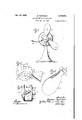
- Figure 1 is a front elevation of a fan embodying my invention, showing one of the blades bent to a position as caused by striking an object.
- Figure 2 is a rear elevation of the fan struc:
- Figure 3 is a perspective view of one of the blades.
- Figure 4 is a sectional view on the line H of 5 Figure 1.
- Y v Figure 5 is a vertical sectional ,view through a modified form of hub.
- Figure 6 is a sectional view on the line 6'6 of Figure 5,
- Figure 7 is a perspective view of the blade shown in Figure 5.
- Figure 8 is a front elevation of still another modified construction of hub and blade; and Figure 9 is a sectional view on the line 9-9 of Figure 8.
- FIG. 1 On the accompanying drawings 1 have used thereference numeral Hi to indicate a fan base, and l2 a fan motor.
- -My fan structure applied to the shaft M of the motor 12 comprises in :0 general a hub A and a plurality of blades 3.
- the hub A may be formed of metal or other relatively rigid material, and as shown in Figures 2 and 4 is provided with a plurality of sockets it. These extend inwardly from the rear face l8 of the 28 hub, and each is provided at its inner end with an enlargement 20.
- the blades B comprise air propelling porti 22, shankportions 24 and enlarged head-like portions 26.
- the slot-like sockets l8, as shown 80 in Figure 4 extend at the desired pitch angle or the bladev relative to the axis of the shaft M and relative to the bore 28 provided therefor'in the hub. Centrifugal force tends, upon rotation of the structure, to urge the blades radially outwardly relative to the hub, but the enlargements 2
- a set screw for I securing the-hub to the shaft.
- z 40 To'retain the blades in position I provide a cover plate 22 which may be suitably secured in position on the face It of the hub A by screws'or the like 34.
- the blades B are formed of some suitable flex- 5 ible material such as rubber, whereby durinsrotation they will substantially maintain their pitch angleagainst the tendency of the air they propel to somewhat flatten the angle.
- the blades upon striking an obiect will bend rearwardly as illustrated by the left blade in Figure 1, so as to not damage the objector the blade.
- the fan can be used without a guard-without danger of injuring a persons hand or the like when assuming a position within the arc of the blade tips.
- the blade material can be quite flexible without the undesired result of the pitch angle being flattened out to an undesirable degree.
- the pitch angle can be increased to compensate for such tendency.
- the blades are assembled relative to the hub by longitudinally sliding the blades into the sockets IS.
- the cover plate 32 then retains them in position.
- Both ends of the sockets may be closed, as shown in Figures 5 and 6, in which similar parts bear the same reference numerals as the preceding figures with the addition of the distinguishing characteristic a, and the hub and blades are indicated as A and B.
- the heads 28a can be squeezed together and forced down through the sockets Ilia, finally registering with the enlargements 20a. and expanding into them. This construction eliminates providing a cover plate for the back end of the hub.
- FIGs 5, 6 and '7 I also illustrate how the sockets l6a may extend axially of the hub, and the blades 3' are then twisted as indicated at 36 adjacent the periphery of the hub to secure the desired pitch of the blades.
- FIGs 8 and 9 I show blades B" and a hub A" which are all formed of rubber or like material moulded in one piece.
- the hub is provided with a metal insert 38 having a bore 40 to receive the motor shaft M.
- the insert 38 has a boss 39 preventing relative rotation between the insert and fan hub.
- a hub having recesses in its periphery closed at their front ends and open at their rear ends to receive the ends of fan blades, fan blades of rubber or similar material having enlarged parts received in said recesses for retaining said blades assembled relative to said hub, said enlarged parts substantially filling said recesses from front to rear EUGENE NE'WNHAM.
Landscapes
- Engineering & Computer Science (AREA)
- Mechanical Engineering (AREA)
- General Engineering & Computer Science (AREA)
- Structures Of Non-Positive Displacement Pumps (AREA)
Description
Deeds, 1939. EW H M 2,183,891
FAN HUB AND BLADE STRUCTURE Filed Dec. '16, 1935 2 Sheets-sheaf 1 E.'NEWNHAM FAN HUB AND BLADEv STRUCTURE Dec. 19, 1939.
Filed Dec. 16, 1935 2 Sheets-Sheet 2 Patented Dec. .19, 1939 burr En STATES PATENT? OFFICE FAN AND BLADE STRUCTURE Eugene New'nham, St. Louis, Mo., assignor to Knapp-Monarch Company, St. Louis, Mo., a
corporation of Application December 16, 1935, Serial No. 54,698 1 Claim. (01. 170-159) The object of my invention is to provide a fan hub and blade structure which is simple, durable and comparatively inexpensive to manufacture. A further object is to provide a fan structure v including blades of rubber or similar semi-rigid and at least semi-flexible material, whereby a a fan is provided which does notneed a guard, since the blades upon striking a persons hand or other object can bend backwardly without l0 injury to' suchobject, the blades afterv clearing the object being again projected to their normal position due to the character of the material of which they are composed, and/or due to the action of centrifugal force. l8 A further object is to provide a fan structure .in which the blades at least are formed of a material which is suiiiciently flexible, upon being struck, to bend and of itself to' resume its original position without permanent distortion, the
: blade, however,.being sumciently rigid that during rotation it will maintain its pitch angle for effectively propelling air.
, A further object is to provide blades which are formed of rubber or the like, either with an in- 2 tegral hub having a drive shaft insert or-individual'biades' set in a hub of metal or the like. Another object is to provide means for retaining fan blades of rubber or the like in a hub,
comprising. enlargements on the blades received so in enlargedportions of sockets in the hub, which sockets receive the blades to retain them in assembled position.
A further object is to provide a fan comprising a hub and a plurality of fan. blades radiating ll therefrom, the hub and blades being of similar material, such material-being flexible, the hub being of such thickness, however, that it is formmaintaining during operation, and the blades being relatively thin so that, although they normally retain their proper position and pitch angle relative to the hub, they can strike an object and bend under the impact thereof without permanent distortion, the blades returning to their original position after passing the object.
.With these and other objects in view, my..invention consists in the construction, arrangement and combinationbf the various parts of the device, whereby the obiects contemplated are attained, as hereinafter more fully set forth,
pointed out in my claim, and illustrated in the accompanying drawings, in which:
Figure 1 is a front elevation of a fan embodying my invention, showing one of the blades bent to a position as caused by striking an object. a 3 Figure 2 is a rear elevation of the fan struc:
tureshowing. a cover plate, the shaft and two of the blades being removed.
Figure 3 is a perspective view of one of the blades.
Figure 4 is a sectional view on the line H of 5 Figure 1. Y v Figure 5 is a vertical sectional ,view through a modified form of hub.
Figure 6 is a sectional view on the line 6'6 of Figure 5,
Figure 7 is a perspective view of the blade shown in Figure 5.
Figure 8 is a front elevation of still another modified construction of hub and blade; and Figure 9 is a sectional view on the line 9-9 of Figure 8.
On the accompanying drawings 1 have used thereference numeral Hi to indicate a fan base, and l2 a fan motor. -My fan structure applied to the shaft M of the motor 12 comprises in :0 general a hub A and a plurality of blades 3. The hub A may be formed of metal or other relatively rigid material, and as shown in Figures 2 and 4 is provided with a plurality of sockets it. These extend inwardly from the rear face l8 of the 28 hub, and each is provided at its inner end with an enlargement 20.
The blades Bcomprise air propelling porti 22, shankportions 24 and enlarged head-like portions 26. The slot-like sockets l8, as shown 80 in Figure 4, extend at the desired pitch angle or the bladev relative to the axis of the shaft M and relative to the bore 28 provided therefor'in the hub. Centrifugal force tends, upon rotation of the structure, to urge the blades radially outwardly relative to the hub, but the enlargements 2|, extending in an other-than-radial direction, engage the head-like portions 26 to counteract such tendency. At I illustrate a set screw for I securing the-hub to the shaft. z 40 To'retain the blades in position, I provide a cover plate 22 which may be suitably secured in position on the face It of the hub A by screws'or the like 34.
- The blades B are formed of some suitable flex- 5 ible material such as rubber, whereby durinsrotation they will substantially maintain their pitch angleagainst the tendency of the air they propel to somewhat flatten the angle. The blades, however, upon striking an obiect will bend rearwardly as illustrated by the left blade in Figure 1, so as to not damage the objector the blade. Thus the fan can be used without a guard-without danger of injuring a persons hand or the like when assuming a position within the arc of the blade tips.
Other material obviously having the desired characteristics can be used.
Besides the tendency of the rubber to maintain the pitch angle centrifugal force aids in such .maintenance.
Any twisting of the blade out of alinement with the socket It brings many points in the twisted portion to a position closer to the hub A, whereas centrifugal force tends constantly to urge all points as far as possible from the hub.
It is, therefore, obvious that the blade material can be quite flexible without the undesired result of the pitch angle being flattened out to an undesirable degree. Obviously, the pitch angle can be increased to compensate for such tendency.
In the form of the invention shown in Figures 2 and 4, the blades are assembled relative to the hub by longitudinally sliding the blades into the sockets IS. The cover plate 32 then retains them in position.
Both ends of the sockets may be closed, as shown in Figures 5 and 6, in which similar parts bear the same reference numerals as the preceding figures with the addition of the distinguishing characteristic a, and the hub and blades are indicated as A and B. As shown by dotted lines in Figure 5, the heads 28a can be squeezed together and forced down through the sockets Ilia, finally registering with the enlargements 20a. and expanding into them. This construction eliminates providing a cover plate for the back end of the hub.
In Figures 5, 6 and '7 I also illustrate how the sockets l6a may extend axially of the hub, and the blades 3' are then twisted as indicated at 36 adjacent the periphery of the hub to secure the desired pitch of the blades.
In Figures 8 and 9 I show blades B" and a hub A" which are all formed of rubber or like material moulded in one piece. The hub is provided with a metal insert 38 having a bore 40 to receive the motor shaft M. The insert 38 has a boss 39 preventing relative rotation between the insert and fan hub.
In all forms of the invention it is preferable to provide closed en s 42, 42a and 42b to conceal the outer end of the motor shaft I.
From the foregoing description it will be ob-- vious that I have provided a fan structure having flexible fan blades of a materialsufllciently stiff to retain the proper pitch for air delivery, and yet flexible or pliable enough to preclude hand or body injury when the fan is used without a guard. Any number of blades, of course, may project from the hub. Various means may be provided for mounting the hub on a rotor shaft of an electric motor or the like, thus providing a fan which does not need a guard, yet which is safe to use.
The blades can be fastened in any suitable manner, and many other changes and modifications besides those illustrated in the drawings can be made without departing from the real spirit and purpose of my invention, and it is my intention to cover by my claim any modified forms of structure, or use of mechanical equivalents, which may be reasonably included within its scope.
I claim as my invention:
In a fan hub and blade structure, a hub having recesses in its periphery closed at their front ends and open at their rear ends to receive the ends of fan blades, fan blades of rubber or similar material having enlarged parts received in said recesses for retaining said blades assembled relative to said hub, said enlarged parts substantially filling said recesses from front to rear EUGENE NE'WNHAM.
Priority Applications (1)
| Application Number | Priority Date | Filing Date | Title |
|---|---|---|---|
| US54698A US2183891A (en) | 1935-12-16 | 1935-12-16 | Fan hub and blade structure |
Applications Claiming Priority (1)
| Application Number | Priority Date | Filing Date | Title |
|---|---|---|---|
| US54698A US2183891A (en) | 1935-12-16 | 1935-12-16 | Fan hub and blade structure |
Publications (1)
| Publication Number | Publication Date |
|---|---|
| US2183891A true US2183891A (en) | 1939-12-19 |
Family
ID=21992909
Family Applications (1)
| Application Number | Title | Priority Date | Filing Date |
|---|---|---|---|
| US54698A Expired - Lifetime US2183891A (en) | 1935-12-16 | 1935-12-16 | Fan hub and blade structure |
Country Status (1)
| Country | Link |
|---|---|
| US (1) | US2183891A (en) |
Cited By (5)
| Publication number | Priority date | Publication date | Assignee | Title |
|---|---|---|---|---|
| US2473665A (en) * | 1946-09-20 | 1949-06-21 | William W K Van Nort | Propeller |
| US2498348A (en) * | 1947-05-29 | 1950-02-21 | Jr Frank E Thompson | Marine propeller |
| US2629545A (en) * | 1949-11-12 | 1953-02-24 | Worthington Corp | Combined fan and power transmission sheave |
| US3332500A (en) * | 1966-08-26 | 1967-07-25 | Ametek Inc | Propeller-type fan blade wheel and method of making the same |
| US20100247316A1 (en) * | 2009-03-25 | 2010-09-30 | Aynsley Richard M | High Efficiency Ducted Fan |
-
1935
- 1935-12-16 US US54698A patent/US2183891A/en not_active Expired - Lifetime
Cited By (6)
| Publication number | Priority date | Publication date | Assignee | Title |
|---|---|---|---|---|
| US2473665A (en) * | 1946-09-20 | 1949-06-21 | William W K Van Nort | Propeller |
| US2498348A (en) * | 1947-05-29 | 1950-02-21 | Jr Frank E Thompson | Marine propeller |
| US2629545A (en) * | 1949-11-12 | 1953-02-24 | Worthington Corp | Combined fan and power transmission sheave |
| US3332500A (en) * | 1966-08-26 | 1967-07-25 | Ametek Inc | Propeller-type fan blade wheel and method of making the same |
| US20100247316A1 (en) * | 2009-03-25 | 2010-09-30 | Aynsley Richard M | High Efficiency Ducted Fan |
| US10054131B2 (en) * | 2009-03-25 | 2018-08-21 | Delta T, Llc | High efficiency ducted fan |
Similar Documents
| Publication | Publication Date | Title |
|---|---|---|
| US2023111A (en) | Silent fan | |
| US1868113A (en) | Fan | |
| US2269287A (en) | Fan | |
| JPS5841299A (en) | Impeller for centrifugal compressor | |
| US2022417A (en) | Air impeller | |
| US2262695A (en) | Fan construction | |
| US2212072A (en) | Fan hub and blade structure | |
| US2183891A (en) | Fan hub and blade structure | |
| US2212041A (en) | Fan wheel | |
| US2056547A (en) | Circulating fan | |
| US2222118A (en) | Propeller | |
| US2552651A (en) | Fan wheel with arcuate blade forming strips | |
| US1843088A (en) | Centrifugal fan | |
| US2144860A (en) | Fan | |
| US2359466A (en) | Air impeller | |
| US2095223A (en) | Fan | |
| US2067410A (en) | Flexible blade fan | |
| US2079044A (en) | Fan and fan blade | |
| US2178047A (en) | Wind driven generator structure | |
| US1146121A (en) | Propeller. | |
| US2838871A (en) | Sounding toy | |
| US2031466A (en) | Fan | |
| US2129939A (en) | Propeller for aircraft | |
| GB434604A (en) | Improvements relating to propellers or screws | |
| US2337700A (en) | Rotary fan |