US217618A - Improvement in automatic car-brakes - Google Patents
Improvement in automatic car-brakes Download PDFInfo
- Publication number
- US217618A US217618A US217618DA US217618A US 217618 A US217618 A US 217618A US 217618D A US217618D A US 217618DA US 217618 A US217618 A US 217618A
- Authority
- US
- United States
- Prior art keywords
- shaft
- car
- brakes
- chain
- wheel
- Prior art date
- Legal status (The legal status is an assumption and is not a legal conclusion. Google has not performed a legal analysis and makes no representation as to the accuracy of the status listed.)
- Expired - Lifetime
Links
Images

Classifications
-
- B—PERFORMING OPERATIONS; TRANSPORTING
- B60—VEHICLES IN GENERAL
- B60T—VEHICLE BRAKE CONTROL SYSTEMS OR PARTS THEREOF; BRAKE CONTROL SYSTEMS OR PARTS THEREOF, IN GENERAL; ARRANGEMENT OF BRAKING ELEMENTS ON VEHICLES IN GENERAL; PORTABLE DEVICES FOR PREVENTING UNWANTED MOVEMENT OF VEHICLES; VEHICLE MODIFICATIONS TO FACILITATE COOLING OF BRAKES
- B60T7/00—Brake-action initiating means
- B60T7/12—Brake-action initiating means for automatic initiation; for initiation not subject to will of driver or passenger
- B60T7/128—Self-acting brakes of different types for railway vehicles
-
- B—PERFORMING OPERATIONS; TRANSPORTING
- B61—RAILWAYS
- B61H—BRAKES OR OTHER RETARDING DEVICES SPECIALLY ADAPTED FOR RAIL VEHICLES; ARRANGEMENT OR DISPOSITION THEREOF IN RAIL VEHICLES
- B61H9/00—Brakes characterised by, or modified for, their application to special railway systems or purposes
- B61H9/003—Brakes characterised by, or modified for, their application to special railway systems or purposes for shunting operation or for narrow gauge trains
Definitions
- PETERS PNOTO LJTHDGRAPHEFL WAsulNGTONrnC.
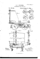
- Figure l is a plan or top view, partly in section, of a car provided with my improved brake mecha'nism.
- Fig. 2 is a vertical longitudinal section of the same; Fig. 3, a detail longitudinal section, on an enlarged scale, of part of said mechanism.
- Fig. 4. is a vertical longitudinal section of the car, showing the mechanism adjusted differently from what it is in Fig. 2.
- Fig. 5 is a front view of the car; Fig. 6, a vertical section of the front part of the car, showing the spring-bar used for taking the brakes ofi.
- Figs. 7, 8, 9, and 10 are detail top views of the devices forv applying and changing the action of the brakes in different positions.
- This invention relates to the employment on railway-cars of mechanism for setting or releasing the brakes automatically or at will by the revolving of the car-wheels, either as the car advances or backs, the arrangement being such that it can be made operative by the traction mechanism, or entirely independent thereof, as may be desired.
- the invention consists in several devices for afl'ecting the position of the friction-wheel, through the agency of which the brakes are applied, and its action in winding up or failing to wind up the chain that leads to the brakes; also, in means for adjusting the degree of friction from the side of the car, and for enabling a person standing on the ground to release or apply the brakes, and in means for protecting the friction mechanism against injury from water and snow, all as hereinafter more fully described.
- letter A represents the frame-work of a suitable car.
- B B are the wheels, and O (J the axles, of the truck 1), that support and carry the car.
- One of these axles carries a cylindrical friction drum or cushion, a.
- Afriction-wheel, b is mounted upon a shaft, d, and serves, when in contact with the cushion a, as in Fig. 4, to wind upon shaft (1 a chain, c, which connects said shaft d with the brake-lever E, and thereby to apply the brakes.
- the lever E connects in the usual or any suitable manner with the brakes F F".
- the shaft d is at one end hung in a link, j, which is pivoted at g to the frame of the truck D. Between its two ends the shaft (1 passes through two other links or hangers, h h, which extend downwardly, and which at their lower ends are pivoted to cars that project from the truck-frame, as shown in Fig. 4. With these hangers f h h the'shaft is free to vibrate toward or away from the axle, and to carry the wheel 1) against or away from the cushion a.
- tallic springs but may be hollow, cylindrical,
- springs may be used. They are, preferably, fitted around rods j that are pivoted to cranks 7c of a shaft, F, which shaft is hung in the truck-frame, and has a handle, I, at one side of the truck-frame, as seen in Figs. 1, 2, and 3.
- the springs i are confined between the hangers h and pins or shoulders m of the rods j, as shown. The degree of compression of the springs i depends, therefore, upon the distance between the hangers h and pins or shoulders m.
- This distance can be regulated by vibrating the shaft F and its cranks k by means of the handle I, and then looking the handle l in a suitable guide-segment, 7%,"Wl1l0h is properly notched at intervals for this purpose.
- rods j free ends of the rods j are guided by the hangers it either by passing through them or by straddling the same, as in Fig. 1, in which latter case the rods j are slotted. They may, however, be connected with shaft'd, if desired.
- an attendant on the ground may regulate the pressure of the springs i at will, so that it will be increased when the car is heavily loaded, and lessened when the load is less, or, in fact, whenever it appears from any causes necessary to thus regulate their pressure.
- a shield or dash-board, G of metal or other material, which I secure to the truck-frame beneath the parts to be thus protected.
- This dash-board is at one end fastened to the central cross-beam, 0, of the truck-frame, and extends thence beneath the wheel I) and cushion a, and is then carried up to the end cross-bar, p, of the truck-frame, as clearly shown in the drawings.
- Its upper face is, preferably, made t", that it may be readily turned therein by a suitable hand-wheel, u.
- a short chain v which is much weaker than the chain t and rod 8 has one of its ends securely fastened to the lower part of the shaft H, while the other end is fastened to the drawhead I of the car in front of said shaft H.
- the upper part of the shaft H carries a collar, w, having two notches, l 2, and a projecting stop-pin, 3, as indicated in Figs. 9 and 10.
- a spring-pawl, y bears against the edge of this collar w. w
- the lower part of the shaft H is not in any bearing, but can move backward and forward in a slotted guide-piece, no, that projects forward from the front of the car, as indicated in Figs. 1 and 6.
- the position of handle 9 as shown in Fig. 4:, is its normal position, and is the position in which it must always be to admit of the brakes being applied.
- the small chain u will be partly wound around the lower end of the shaft H and shortened, to spring the lower end of the shaft H forward, as indicated in Fig. 6.
- the stout chain t is thereby drawn suflicient to hold the shaft 01 forward and prevent contact between the wheel I) and cushion a when the draw-head is not pressed back; but as soon as forward movement of the car is resisted at the front, the chain it will again be sufficiently slackened to enable the shaft H to resume its vertical position, and to permit the springs z to crowd the wheel 1) against the cushion a, and to therefore apply the brakes.
- the chain 4 is made weaker than the chain 15, so that if from any cause a breakage should occur it will be in the chain 1), the rupture of which, while the train is moving forward, will cause the immediate application of the brakes, as it will enable the shaft H to spring back into its normal upright position.
- the brakeman in order to apply the brakes to a moving car, will only have to take the pawl 31 out of the notch 2, and to allow the shaft H to spring back and to unwind the weak chain 21, thereby bringing the stop 3 against the pawl y, as in Fig. 1.
- the chain t is attached to the shaft H by a ring or swivel placed loosely around said shaft, and cannot be wound upon the same. Its tension is only varied as the lower end of the shaft H is sprung more or less forward, as indicated in Fig. 6, by the winding of the chain c or entirely swung back into the normal position.
- the brakes to be instantaneously applied, whatever may be the direction of the moving car, by bringing the shaft H into the position shown in Fig. 1, or cause the brake appliance to be off while the car is being pulled ahead, and to be automatically applied as soon as any considerable resistance in front to its forward movement occurs, by placing the shaft H in the position shown in Fig. 9, and handle a pointing in the direction in which the train is bein g drawn, while handle g remains in its normal position; but the moment that resistance in front ceases or the train moves backward, the brakes are released, or, in other words, cease to operate.
- This mechanism consists of the vertical shaft J, hung to the end of the car in proper bear ings, so that it may be freely turned in said bearings by means of a suitable handle, (H, which also serves as an indicator to show whether the brake will be applied by moving the car backward, forward, or in either direction.
- the lower end of the shaft J carries a grooved disk or pulley, b To the edge of this pulley are fastened at diametrically-opposite points the ends of two check-chains, c and d which extend back to and connect with the free end of the vibrating shaft 01, as seen in Fig. 1.
- the chains 0 (1 where they pass through the frame-work of the truck D, may be guided through suitable loops or eyes W, or over suitable friction-pulleys 6 or other proper provision may be made to prevent their entanglement.
- crank-shaft F with the rod j, having shoulder m, spring 6, and vibrating shaft (1, which carries the friction-wheel b of a brake mechanism, substantially as herein shown and described.
- the dashboard G placed beneath said wheel and cushion, and connected to the beam D and end crossbar 10 of the truck, substantially as herein shown and described.
- the hand-wheel shaft H hung in bearings at its upper, and left free to spring forward and backward at its lower, part, and connected with the draw-head I and brake-wheel shaft d of a railway-car, substantially as herein shown and described, for the purposes stated.
- the shaft H provided with the collar to, having one or more notches, in combination with the pawl 1 chains 1. and v, and with the vibrating shaft d, carrying the brake-wheel b, for operation substantially as herein shown and described.
- the shaft J made with the pulley b and combined with the chains 0 which are secured to opposite sides of said pulley, and with the vibrating shaft 01, substantially as herein shown and described.
Landscapes
- Engineering & Computer Science (AREA)
- Mechanical Engineering (AREA)
- Transportation (AREA)
- Braking Arrangements (AREA)
Description
2 Sheets-Sheet 1.
1). A. HOPKINS. Automatic Gar-Brake.
Patented July 15,1879
Ali
2 SheetsSheet 2; D. A. HOPKINS. Automatic Gar-Brake.
, isfig Patented Jul' 15 N. PETERS, PNOTO LJTHDGRAPHEFL WAsulNGTONrnC.
UNITED STATES PATENT OEEIoE.
DAVID A. HOPKINS, OF PARK RIDGE, NEW JERSEY.
IMPROVEMENT IN AUTOMATIC CAR-BRAKES.
Specification forming part of Letters Patent No. 217,618, dated July 15, 1879; application filed May 6, 1879.
To all whom it may concern:
Be it known that I, DAVID A. HOPKINS, of Park Ridge, in the county of Bergen and State of New Jersey, have invented a new and Improved Brake Mechanism for Railroad-Oars, of which the following is a specification.
Figure l is a plan or top view, partly in section, of a car provided with my improved brake mecha'nism. Fig. 2 is a vertical longitudinal section of the same; Fig. 3, a detail longitudinal section, on an enlarged scale, of part of said mechanism. Fig. 4. is a vertical longitudinal section of the car, showing the mechanism adjusted differently from what it is in Fig. 2. Fig. 5 is a front view of the car; Fig. 6, a vertical section of the front part of the car, showing the spring-bar used for taking the brakes ofi. Figs. 7, 8, 9, and 10 are detail top views of the devices forv applying and changing the action of the brakes in different positions.
Similar letters of reference indicate corresponding parts in all the figures.
. This invention relates to the employment on railway-cars of mechanism for setting or releasing the brakes automatically or at will by the revolving of the car-wheels, either as the car advances or backs, the arrangement being such that it can be made operative by the traction mechanism, or entirely independent thereof, as may be desired.
The invention consists in several devices for afl'ecting the position of the friction-wheel, through the agency of which the brakes are applied, and its action in winding up or failing to wind up the chain that leads to the brakes; also, in means for adjusting the degree of friction from the side of the car, and for enabling a person standing on the ground to release or apply the brakes, and in means for protecting the friction mechanism against injury from water and snow, all as hereinafter more fully described.
In the drawings, letter A represents the frame-work of a suitable car. B B are the wheels, and O (J the axles, of the truck 1), that support and carry the car. One of these axles carries a cylindrical friction drum or cushion, a. Afriction-wheel, b, is mounted upon a shaft, d, and serves, when in contact with the cushion a, as in Fig. 4, to wind upon shaft (1 a chain, c, which connects said shaft d with the brake-lever E, and thereby to apply the brakes.
There is nothing new in the use of the friction-wheel b, cushion a, shaft 01, and chain c, in link f, or in the use of hangers for carrying shaft (1, hereinafter referred to, when they are attached to the car-frame instead of to the truck, as in this case.
The lever E connects in the usual or any suitable manner with the brakes F F". The shaft d is at one end hung in a link, j, which is pivoted at g to the frame of the truck D. Between its two ends the shaft (1 passes through two other links or hangers, h h, which extend downwardly, and which at their lower ends are pivoted to cars that project from the truck-frame, as shown in Fig. 4. With these hangers f h h the'shaft is free to vibrate toward or away from the axle, and to carry the wheel 1) against or away from the cushion a.
Sprm gs 'b t bear against the hangers h h, and
tallic springs, but may be hollow, cylindrical,
rubber, elliptic, or of other kind, and one or more springs may be used. They are, preferably, fitted around rods j that are pivoted to cranks 7c of a shaft, F, which shaft is hung in the truck-frame, and has a handle, I, at one side of the truck-frame, as seen in Figs. 1, 2, and 3. The springs i are confined between the hangers h and pins or shoulders m of the rods j, as shown. The degree of compression of the springs i depends, therefore, upon the distance between the hangers h and pins or shoulders m. This distance can be regulated by vibrating the shaft F and its cranks k by means of the handle I, and then looking the handle l in a suitable guide-segment, 7%,"Wl1l0h is properly notched at intervals for this purpose. The
free ends of the rods j are guided by the hangers it either by passing through them or by straddling the same, as in Fig. 1, in which latter case the rods j are slotted. They may, however, be connected with shaft'd, if desired.
By means of the handle I an attendant on the ground may regulate the pressure of the springs i at will, so that it will be increased when the car is heavily loaded, and lessened when the load is less, or, in fact, whenever it appears from any causes necessary to thus regulate their pressure.
It will be perceived that all the pivoted hangers f, h, and h, in which the shaft 01 has its bearings, are connected to the frame of the truck D, and not to that of the car, as hangers corresponding to hangers h h heretofore have been, and that therefore the relative position of the shaft 01 to the other parts of the truck remains unaffected when the car moves on a curved track. This is very important, as it renders the action of the brake mechanism equally positive whether the car moves in a straight direction or along curves.
In order to prevent track-water from being splashed against the cushion a and wheel b, and to also protect these parts from injury'by snow, cinders, and other obstructions whirled up during the rapid progress of the car, I have devised a shield or dash-board, G, of metal or other material, which I secure to the truck-frame beneath the parts to be thus protected. This dash-board is at one end fastened to the central cross-beam, 0, of the truck-frame, and extends thence beneath the wheel I) and cushion a, and is then carried up to the end cross-bar, p, of the truck-frame, as clearly shown in the drawings. Its upper face is, preferably, made t", that it may be readily turned therein by a suitable hand-wheel, u.
A short chain v, which is much weaker than the chain t and rod 8, has one of its ends securely fastened to the lower part of the shaft H, while the other end is fastened to the drawhead I of the car in front of said shaft H. The upper part of the shaft H carries a collar, w, having two notches, l 2, and a projecting stop-pin, 3, as indicated in Figs. 9 and 10. A spring-pawl, y, bears against the edge of this collar w. w
The lower part of the shaft H is not in any bearing, but can move backward and forward in a slotted guide-piece, no, that projects forward from the front of the car, as indicated in Figs. 1 and 6.
Now, whenever -the shaft H is in its normal position, with the pawl 1 bearing against the stop-pin 3 of the collar w, as in Fig. 1, the shaft H is quite vertical, leaving the stout chain it slack. The springs i are, therefore, at liberty to press the wheel 1) against the cushion a, and the brakes are consequently applied as soon as the car is moved either forward or backward, provided that the handle or indicator a is in the position shown in Fig. 1, and the handle g in the position shown in Fig. 4. Even if traction is applied the draw-head I will not pull on the chain c sufficient to disturb the position of the shaft H. The position of the shaft H and handles 0!. and g just described is, therefore, that for applying the brakes under all conditions.
The position of handle 9 as shown in Fig. 4:, is its normal position, and is the position in which it must always be to admit of the brakes being applied.
If the shaft H is turned to bring the pawl y into the first notch, 1, as in Fig. 9, the small chain u will be partly wound around the lower end of the shaft H and shortened, to spring the lower end of the shaft H forward, as indicated in Fig. 6. The stout chain t is thereby drawn suflicient to hold the shaft 01 forward and prevent contact between the wheel I) and cushion a when the draw-head is not pressed back; but as soon as forward movement of the car is resisted at the front, the chain it will again be sufficiently slackened to enable the shaft H to resume its vertical position, and to permit the springs z to crowd the wheel 1) against the cushion a, and to therefore apply the brakes. This, therefore, is the safe position, with handle or indicator a? pointing in the direction that the train is being drawn, and handle 9 is in the position shown in Fig. 4, for the running of the train, as it will cause the brakes to be off as long as the train is being drawn ahead, but will insure the automatic application of the brakes as soon as forward'movement of the car is resisted sufficiently to somewhat compress the draw-head springs, while in case of backing up the train the brake is taken off by the winding up of check-chain c or d on shaft d, and drawing it back.
The chain 4; is made weaker than the chain 15, so that if from any cause a breakage should occur it will be in the chain 1), the rupture of which, while the train is moving forward, will cause the immediate application of the brakes, as it will enable the shaft H to spring back into its normal upright position.
If the shaft H is still further turned to bring the pawl yinto the notch 2, as in Fig. 10, the chain Q) is still further wound around the shaft H, and the lower end of the said shaft thereby still further sprung forward and the chain t tightened to such an extent that the wheel I) will be thereby drawn and held away from the cushion u, even if the locomotive drawing the train is reversed to resist the forward movement of the train, or if the train be pushed or backed. This, therefore, is the position for running the train in the ordinary manner without automatic-brake appliance, whether the train is being moved forward, backward, or stopped. The brakeman, in order to apply the brakes to a moving car, will only have to take the pawl 31 out of the notch 2, and to allow the shaft H to spring back and to unwind the weak chain 21, thereby bringing the stop 3 against the pawl y, as in Fig. 1. The chain t, it will be observed, is attached to the shaft H by a ring or swivel placed loosely around said shaft, and cannot be wound upon the same. Its tension is only varied as the lower end of the shaft H is sprung more or less forward, as indicated in Fig. 6, by the winding of the chain c or entirely swung back into the normal position.
This arrangement of chains v and t with shaft H, I regard as producing the best results in use; but when desirable chain t may be extended direct to and connected with the draw-head, with'such connection with shaft H that by winding upon the part of the chain between the draw-head and said shaft the shaft shall be drawn forward, as above described.
It will be observed that by the mechanism already described, with handle a in the position shown in Fig. 1, and handle g in the position shown in Fig. 4, the car, when running, is, as to the application of its brake, under complete control of the brakeman riding on it, who can either render it absolutely free from all automatic braking by turning the shaft H into the position shown in Fig. 10, or
cause the brakes to be instantaneously applied, whatever may be the direction of the moving car, by bringing the shaft H into the position shown in Fig. 1, or cause the brake appliance to be off while the car is being pulled ahead, and to be automatically applied as soon as any considerable resistance in front to its forward movement occurs, by placing the shaft H in the position shown in Fig. 9, and handle a pointing in the direction in which the train is bein g drawn, while handle g remains in its normal position; but the moment that resistance in front ceases or the train moves backward, the brakes are released, or, in other words, cease to operate.
I will now more fully describe the mechanism directly connected with shaft J for con; trolling the operation of the brakes while the car is moving; but in order to control the operation of the brake through said mechanism it is necessary that the shaft H be in its normal vertical position indicated in Fig. 1, so that the chain t is slack, and that the handle 91 be in its normal position shown in Fig. 4.
This mechanism consists of the vertical shaft J, hung to the end of the car in proper bear ings, so that it may be freely turned in said bearings by means of a suitable handle, (H, which also serves as an indicator to show whether the brake will be applied by moving the car backward, forward, or in either direction. The lower end of the shaft J carries a grooved disk or pulley, b To the edge of this pulley are fastened at diametrically-opposite points the ends of two check-chains, c and d which extend back to and connect with the free end of the vibrating shaft 01, as seen in Fig. 1.
When the handle a is turned to the side, as in Fig. 1, both chains 0 and d are quite slack, and the springs i are therefore at liberty to operate in applying the brakes in manner already stated. This, it will be remembered, must be the position of handle a and chains 0 01 when the brake mechanism is to be controlled by means of the springing shaft H. When the handle a is turned forward, as in Fig. 8, the chain 0 whose front end is under the handle a is wound around one-fourth of the pulley b and thereby stretched j ust enough, so that by its winding around the shaft d when the same is turned during the backward movement of the car it will be drawn tight and pull said shaft away from the axle before chain c is wound up enough to apply the brakes. Thus as the car is backed the wheel b, which is still in contact with the cushion a, is turned, but immediately winds the chain 0 upon the shaft (1, and is thereby drawn forward to interrupt contact between the wheel I) and cushion a, preventing by this means the winding of the chain 0 around the shaft d to any considerable extent, and the consequent application of the brakes; but when the car is moving forward the chain 6 is wound upon the shaft (1, and the brakes are applied before the shaft d can commence to wind up the chain c enough to draw wheel 11 away from cushion a and prevent the application of the brakes. The brakes are therefore applied as the car advances. Now, if handle a is turned so as to point in the opposite direction, the action of chains 0 and d will be reversed, and the brake will be applied only as the car advances in that direction, and will be at once released by moving the car in the opposite direction, while by placing said handle or indicator in the position shown in Fig. 1, both of said chains will be slackened to such extent that chain 0 will be wound up on shaft (1, and the brakes applied before the wheel I) will be drawn away from cushion a by the winding up of either of said check-chains, the result being that the moving of the car in either direction will cause the application of the brakes. This action of the chains 0 and d is insured by their being wound about half around the shaft d before the chain c is wound up at all.
In performing the work of starting, moving, and stopping of freight-cars in yards and depots, commonly known as drilling, great inconvenience, labor, loss of time, and endangering of life results from the necessity of attendants climbing to the top of house or box cars in order to release or apply the brakes. To obviate these difliculties I have provided a device for releasing and applying the brakes by an attendant standing upon the ground near the car. This device consists of a horizontal transverse shaft, L, carrying in line with the chains 0 d a rectangular or other open frame or enlargement, j, which is hung in the frame A of the car, and provided at the side of the car with a handle, 9 which is conveniently accessible from the ground. The
chains 0 01 are drawn through this open frame or enlargement f by bringing them over one and under the other cross-bar of said frame, in the manner indicated in Fig. 4. When the brakes are to be at all applied said frame f 2 mustbein anearly horizontal position. (Shown in Fig. 4.) In order that the brakes may be completely controlled in both releasing and applying them by this device, shafts H and J must both be in their normal position.
By turning the shaft L, by means of the handle g one-quarter around, the frame f will be raised to the upright position, (shown in Fig. 2,) and the chains 0 (Z are thereby stretched to such extent as to pull the shaftd forward and the wheel b entirely off the cushion a, thus insuring absolute freedom from antomatic application of the brakes in the movements of the car either backward or forward; but as soon as the handle g is moved down into the position shown in Fig. 4, and the frame or enlargement f thereby set horizontal, the chains 0 and d are slackened, resultin g in the immediate application of the brakes, in manner hereinbefore specified.
The chains 0 (1 where they pass through the frame-work of the truck D, may be guided through suitable loops or eyes W, or over suitable friction-pulleys 6 or other proper provision may be made to prevent their entanglement.
It is not absolutely necessary that the exact arrangement of springs with crank-shaft F and handle I here shown shall in all cases be adhered to; but it is imperatively necessary that the arrangement of one or more springs with handle I and shaft F, or its equivalent, shall in all cases be such that adhesion of wheel 1) upon cushion a is regulated by the moving of said handle and shaft, substantially the same as herein shown and described.
I claim- 1. In a car-truck, the vibrating shaft (7, carrying the friction-wheel b, and connected with the brake-chain 0, in combination with the pressure-springs 1', bearing against the shaft 01, and with mechanism for regulating the pressure of the springs by means of a handle, I, at the side of the truck without thereby changing the position of the shaft (1, substantially as herein shown and described.
2. The combination of the crank-shaft F with the rod j, having shoulder m, spring 6, and vibrating shaft (1, which carries the friction-wheel b of a brake mechanism, substantially as herein shown and described.
3. In combination with a car-truck, having friction-cushion a and friction-wheel I), for the application of the brake mechanism, the dashboard G, placed beneath said wheel and cushion, and connected to the beam D and end crossbar 10 of the truck, substantially as herein shown and described.
4. The combination of the vibrating shaft d,
carrying the friction-wheel b, with the chain t, hand-wheel shaft H, and chain c, the chain it being swiveled to the shaft H, so that said shaft will be sprung forward by turning it and winding up the chain, substantially as herein shown and described.
5. The hand-wheel shaft H, hung in bearings at its upper, and left free to spring forward and backward at its lower, part, and connected with the draw-head I and brake-wheel shaft d of a railway-car, substantially as herein shown and described, for the purposes stated.
6. The combination of the draw-head I and chain 12, with the springing and rotating shaft H, hand-wheel a, chain t, and vibrating brakewheel shaft d, substantially as herein shown and described.
7. The combination of the vibrating shaft 01, carrying wheel I), with the spring or springs i, friction-collar a, and with the chain t, springing shaft H, and winding-chain a, substantially as herein shown and described.
8. The shaft H, provided with the collar to, having one or more notches, in combination with the pawl 1 chains 1. and v, and with the vibrating shaft d, carrying the brake-wheel b, for operation substantially as herein shown and described.
9. The vibrating brake-wheel shaft d, combined with the chains 0 61 and e, and with the shaft J, substantially as shown, for the purposes herein shown and described.
10. The shaft J, made with the pulley b and combined with the chains 0 which are secured to opposite sides of said pulley, and with the vibrating shaft 01, substantially as herein shown and described.
11. The combination of the brake-wheel shaft 0?, spring z, and winding-cushion a, with the brake-chain e, and with the chains 0 d that extend from the shaft d to opposite sides of the wheel b substantially as herein shown and described.
12. The combination of the stretching de vice f on shaft I with the chain or chains of a brake mechanism, and with a handle, 9 ,0011- veniently accessible, for permitti ug the stretching of said chain or chains and the entire release of the brake mechanism, substantially as specified.
18. The combination of the vibrating shaft d, chains 0 W, and shaft J with the transverse shaft L and open frame or enlargement f thereon, substantially as herein shown-and described.
14. The combination of one or more springs with crank-shaft F and handle l, whereby the pressure of wheel 1) against cushion a is regulated, substantially as set forth.
DAVID A. HOPKINS.
Witnesses:
F. v. BRIESEN, W. G. E. SCHULTZ.
Publications (1)
| Publication Number | Publication Date |
|---|---|
| US217618A true US217618A (en) | 1879-07-15 |
Family
ID=2287020
Family Applications (1)
| Application Number | Title | Priority Date | Filing Date |
|---|---|---|---|
| US217618D Expired - Lifetime US217618A (en) | Improvement in automatic car-brakes |
Country Status (1)
| Country | Link |
|---|---|
| US (1) | US217618A (en) |
-
0
- US US217618D patent/US217618A/en not_active Expired - Lifetime
Similar Documents
| Publication | Publication Date | Title |
|---|---|---|
| US217618A (en) | Improvement in automatic car-brakes | |
| US152093A (en) | Improvement in railway-car brakes | |
| US322597A (en) | Car-brake | |
| US363382A (en) | Car-brake | |
| US213305A (en) | Improvement in car-brakes | |
| US318775A (en) | Automatic car-brake | |
| US243055A (en) | Car-brake | |
| US329328A (en) | Car-brake | |
| US276938A (en) | torrey | |
| US272097A (en) | s stowe | |
| US249226A (en) | Car-brake | |
| US294570A (en) | Car brake | |
| US250822A (en) | lanphbe | |
| US486453A (en) | Automatic car-brake | |
| US806849A (en) | Car-brake. | |
| US293119A (en) | Car-starter | |
| US299741A (en) | Car-brake | |
| US224966A (en) | George b | |
| US276930A (en) | torrey | |
| US10701A (en) | Joseph marks | |
| US408567A (en) | Automatic car-brake | |
| US695274A (en) | Means for providing brakes to railway-vehicles. | |
| US410881A (en) | de foresta | |
| US291841A (en) | fairman | |
| US365487A (en) | Emeegency beake toe eailwat oaes |