US2148990A - Ornament - Google Patents
Ornament Download PDFInfo
- Publication number
- US2148990A US2148990A US154267A US15426737A US2148990A US 2148990 A US2148990 A US 2148990A US 154267 A US154267 A US 154267A US 15426737 A US15426737 A US 15426737A US 2148990 A US2148990 A US 2148990A
- Authority
- US
- United States
- Prior art keywords
- strip
- ornament
- core
- turns
- diameter
- Prior art date
- Legal status (The legal status is an assumption and is not a legal conclusion. Google has not performed a legal analysis and makes no representation as to the accuracy of the status listed.)
- Expired - Lifetime
Links
- 239000000463 material Substances 0.000 description 12
- 230000000694 effects Effects 0.000 description 4
- 239000000725 suspension Substances 0.000 description 4
- 235000004507 Abies alba Nutrition 0.000 description 2
- 241000191291 Abies alba Species 0.000 description 2
- 239000003086 colorant Substances 0.000 description 2
- 239000007799 cork Substances 0.000 description 2
- 238000004519 manufacturing process Methods 0.000 description 2
- 239000002184 metal Substances 0.000 description 2
- 238000000034 method Methods 0.000 description 2
- 238000005096 rolling process Methods 0.000 description 2
- 229920002160 Celluloid Polymers 0.000 description 1
Images
Classifications
-
- A—HUMAN NECESSITIES
- A47—FURNITURE; DOMESTIC ARTICLES OR APPLIANCES; COFFEE MILLS; SPICE MILLS; SUCTION CLEANERS IN GENERAL
- A47G—HOUSEHOLD OR TABLE EQUIPMENT
- A47G33/00—Religious or ritual equipment in dwelling or for general use
- A47G33/04—Christmas trees
- A47G33/08—Christmas tree decorations
- A47G33/0845—Artificial snow, ice or icicles
-
- Y—GENERAL TAGGING OF NEW TECHNOLOGICAL DEVELOPMENTS; GENERAL TAGGING OF CROSS-SECTIONAL TECHNOLOGIES SPANNING OVER SEVERAL SECTIONS OF THE IPC; TECHNICAL SUBJECTS COVERED BY FORMER USPC CROSS-REFERENCE ART COLLECTIONS [XRACs] AND DIGESTS
- Y10—TECHNICAL SUBJECTS COVERED BY FORMER USPC
- Y10T—TECHNICAL SUBJECTS COVERED BY FORMER US CLASSIFICATION
- Y10T29/00—Metal working
- Y10T29/49—Method of mechanical manufacture
- Y10T29/49588—Jewelry or locket making
-
- Y—GENERAL TAGGING OF NEW TECHNOLOGICAL DEVELOPMENTS; GENERAL TAGGING OF CROSS-SECTIONAL TECHNOLOGIES SPANNING OVER SEVERAL SECTIONS OF THE IPC; TECHNICAL SUBJECTS COVERED BY FORMER USPC CROSS-REFERENCE ART COLLECTIONS [XRACs] AND DIGESTS
- Y10—TECHNICAL SUBJECTS COVERED BY FORMER USPC
- Y10T—TECHNICAL SUBJECTS COVERED BY FORMER US CLASSIFICATION
- Y10T29/00—Metal working
- Y10T29/49—Method of mechanical manufacture
- Y10T29/49609—Spring making
Definitions
- My invention relates to ornaments.
- An object of my invention is to provide a relatively simple and highly ornamental device comprising a strip of thin sheet-like material having highly polished flat surfaces.
- Another object of my invention is to provide an ornament of pleasing form and effect.
- Another object of my invention is to provide an ornament particularly useful as a pendant, and on Christmas trees.
- Another object of my invention is to provide a relatively simple and ellcient method of making the ornaments embodying my invention.
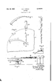
- Figure 1 is a View, in perspective, of a strip of material from which the device embodying my invention is formed
- Fig. 2 is a partial top plan view of a device for forming the ornament embodying my invention
- Fig. 3 is a view, in front elevation, of the ornament embodying my invention.
- Fig. 4 is a fragmentary view, in vertical section, taken on the line 4 4 of Fig. 2, and,
- Fig. 5 is a partial side elevational view of the device shown in Fig. 2.
- Fig. 1 of the drawing I have there illustrated the initial form of the strip of material I I from which the ornament embodying my invention is made.
- the strip is of arcuate wedge shape having a suspension opening I3 at the wider end thereof.
- Fig. 3 of the drawing shows the finished form after the strip I I has been subjected to a rolling or forming action, as will be hereinafter described. While I may use glazed paper, or Celluloid, I prefer to use relatively thin sheet metal differently colored on the two ilat sides and highly polished to reflect light falling on the curved surfaces.
- My improved ornament may be used in substantially any position, but I have found it to appear most pleasing when suspended as by a small hook or a loop of cord extending through the opening I3. I have obtained pleasing ornamental effects by the use of ornaments of this kind suspended from the branches of Christmas trees, by reason of the reflected-light effects from the vari-colored inner and outer surfaces of the strip of material.
- the general shape of the finished ornament I5 is that of an extended cone-shaped spiral, the diameter of the lowermost turn, that is at that end of the strip which is the narrowest, is smaller than the diameter of the uppermost turn where the strip is the Widest. It is therefore evident that the diameter of any turn increases with the width of the strip comprised in that turn. It will' be further notedthat the distance between adjacent edges of the material of the successive turns increases but slightly with the diameter of the turns as well as with the width of the strip of material.
- Another way of describing the general shape of the cone-shaped spiral is to say that it is of generally corkscrew shape with the greater width of the strip extending longitudinally of the device, or that the strip is wound fiatwise into an open coil extended spiral.
- a substantially ilat table II is rotatably supported on a suitable bearing standard I9, and I have s hown a pulley 2l and a driving belt 23 therearound to indicate that the table I'I is adapted to be rotated by any suitable power means.
- a core 25 of substantially cone-shape is rotatably supported in a suitable standard 21, the longitudinal axis of the core 25 being inclined relatively to the top surface of the table so that, as shown particularly in Fig. 5 of the drawing, the outer surface of the core 25 is substantially parallel to the top surface of the table. The distance therebetween will be substantially equal to the thickness of the strip of material Il.
- the smaller end of the core 25 is provided with a diametral slot 29 to receive the narrow end of the strip l I in substantially the manner shown in Fig. 4 of the drawing.
- the narrow end of the strip II is bent substantially at right angles to the plane of the strip and substantially parallel to the narrow end thereof and inserted into the slot 29.
- the table I'I is then caused to turn in a clockwise direction as seen in Fig. 2 of the drawing and as shown by the arrow 3l, whereby the strip II is rolled up on the core to substantially the shape shown in Fig. 3 of the drawing, and can be removed therefrom by a longitudinal movement toward the smaller end of the core 25.
- I preferably use relatively thin sheet metal having highly polished flat sides and I may make the two sides of different colors or of the same colors with the idea of providing highly refiectant surfaces giving a pleasing effect when subjected to either daylight or to artificial light.
- the arcuate wedge shape of the strip II is an important element in obtaining the nal form shown in Fig. 3.
- the use of a straight wedge shaped strip wound on a cone shaped core would result in crowding the turns at one end of the completed device and a large distance between adjacent edges of the material at the other end of the turn, thereby providing a dissyrnmetrical appearing cone-shaped spiral.
- the curvature of the strip has a definite relation to the position of the respective turns longitudinally of the open-coil cone-shaped eX- tended spiral.
Landscapes
- Adornments (AREA)
Description
Feb. 2s, 1939. R. HJORDAN 2,148,990
ORNAMENT Filed July 17, 1937 Patented Feb. 28, 1939 UNITED STATES PATENT OFFICE 3 Claims.
My invention relates to ornaments.
An object of my invention is to provide a relatively simple and highly ornamental device comprising a strip of thin sheet-like material having highly polished flat surfaces.
Another object of my invention is to provide an ornament of pleasing form and effect.
Another object of my invention is to provide an ornament particularly useful as a pendant, and on Christmas trees.
Another object of my invention is to provide a relatively simple and ellcient method of making the ornaments embodying my invention.
Other objects will hereinafter appear.
In the single sheet of drawings,
Figure 1 is a View, in perspective, of a strip of material from which the device embodying my invention is formed,
Fig. 2 is a partial top plan view of a device for forming the ornament embodying my invention,
Fig. 3 is a view, in front elevation, of the ornament embodying my invention,
Fig. 4 is a fragmentary view, in vertical section, taken on the line 4 4 of Fig. 2, and,
Fig. 5 is a partial side elevational view of the device shown in Fig. 2.
Referring iirst to Fig. 1 of the drawing, I have there illustrated the initial form of the strip of material I I from which the ornament embodying my invention is made. As will be seen the strip is of arcuate wedge shape having a suspension opening I3 at the wider end thereof. Fig. 3 of the drawing shows the finished form after the strip I I has been subjected to a rolling or forming action, as will be hereinafter described. While I may use glazed paper, or Celluloid, I prefer to use relatively thin sheet metal differently colored on the two ilat sides and highly polished to reflect light falling on the curved surfaces.
My improved ornament may be used in substantially any position, but I have found it to appear most pleasing when suspended as by a small hook or a loop of cord extending through the opening I3. I have obtained pleasing ornamental effects by the use of ornaments of this kind suspended from the branches of Christmas trees, by reason of the reflected-light effects from the vari-colored inner and outer surfaces of the strip of material.
The general shape of the finished ornament I5 is that of an extended cone-shaped spiral, the diameter of the lowermost turn, that is at that end of the strip which is the narrowest, is smaller than the diameter of the uppermost turn where the strip is the Widest. It is therefore evident that the diameter of any turn increases with the width of the strip comprised in that turn. It will' be further notedthat the distance between adjacent edges of the material of the successive turns increases but slightly with the diameter of the turns as well as with the width of the strip of material. Another way of describing the general shape of the cone-shaped spiral is to say that it is of generally corkscrew shape with the greater width of the strip extending longitudinally of the device, or that the strip is wound fiatwise into an open coil extended spiral.
I have shown in Figs. 2, 4 and 5 a means for practicing a method of forming an ornament of this kind, which method I have found very satisfactory. A substantially ilat table II is rotatably supported on a suitable bearing standard I9, and I have s hown a pulley 2l and a driving belt 23 therearound to indicate that the table I'I is adapted to be rotated by any suitable power means. A core 25 of substantially cone-shape is rotatably supported in a suitable standard 21, the longitudinal axis of the core 25 being inclined relatively to the top surface of the table so that, as shown particularly in Fig. 5 of the drawing, the outer surface of the core 25 is substantially parallel to the top surface of the table. The distance therebetween will be substantially equal to the thickness of the strip of material Il.
The smaller end of the core 25 is provided with a diametral slot 29 to receive the narrow end of the strip l I in substantially the manner shown in Fig. 4 of the drawing. The narrow end of the strip II is bent substantially at right angles to the plane of the strip and substantially parallel to the narrow end thereof and inserted into the slot 29. The table I'I is then caused to turn in a clockwise direction as seen in Fig. 2 of the drawing and as shown by the arrow 3l, whereby the strip II is rolled up on the core to substantially the shape shown in Fig. 3 of the drawing, and can be removed therefrom by a longitudinal movement toward the smaller end of the core 25.
I preferably use relatively thin sheet metal having highly polished flat sides and I may make the two sides of different colors or of the same colors with the idea of providing highly refiectant surfaces giving a pleasing effect when subjected to either daylight or to artificial light.
I wish to point out that the arcuate wedge shape of the strip II is an important element in obtaining the nal form shown in Fig. 3. Thus the use of a straight wedge shaped strip wound on a cone shaped core would result in crowding the turns at one end of the completed device and a large distance between adjacent edges of the material at the other end of the turn, thereby providing a dissyrnmetrical appearing cone-shaped spiral. The curvature of the strip has a definite relation to the position of the respective turns longitudinally of the open-coil cone-shaped eX- tended spiral.
While I have illustrated a specic form of machine for rolling up the initially flat arcuate wedge-shaped strip of material, I do not wish to be limited thereto as any other machine effective for the same purpose may be employed to practice the above described method of making my new and improved ornament.
I claim as my invention:
1. An ornamental device for suspension from a support and comprising an open-coil extended spiral of a wedge-shaped arcuate strip of material.
2. An ornamental device of generally cork screw shape for suspension from a support and comprising an arcuate strip of highly polished thin strip material of varying width wound atwise, the diameter of the respective turns increasing with increase in the width of the strip.
3. An ornamental device of generally cork screw shape for suspension from a support and comprising an arcuate strip of highly polished thin material of varying width wound iiatwise, the diameter of the respective turns increasing with increase in the width of the strip and the distance between adjacent turns increasing only slightly with the increase in the diameter of the turns.
RICHARD H. JORDAN.
Priority Applications (1)
| Application Number | Priority Date | Filing Date | Title |
|---|---|---|---|
| US154267A US2148990A (en) | 1937-07-17 | 1937-07-17 | Ornament |
Applications Claiming Priority (1)
| Application Number | Priority Date | Filing Date | Title |
|---|---|---|---|
| US154267A US2148990A (en) | 1937-07-17 | 1937-07-17 | Ornament |
Publications (1)
| Publication Number | Publication Date |
|---|---|
| US2148990A true US2148990A (en) | 1939-02-28 |
Family
ID=22550677
Family Applications (1)
| Application Number | Title | Priority Date | Filing Date |
|---|---|---|---|
| US154267A Expired - Lifetime US2148990A (en) | 1937-07-17 | 1937-07-17 | Ornament |
Country Status (1)
| Country | Link |
|---|---|
| US (1) | US2148990A (en) |
Cited By (4)
| Publication number | Priority date | Publication date | Assignee | Title |
|---|---|---|---|---|
| US3983652A (en) * | 1971-09-17 | 1976-10-05 | Elinore Beaty | Illuminated display having remote light source |
| US5329789A (en) * | 1993-05-05 | 1994-07-19 | Almond Jewelers Inc. | Jewelry with tubular appearance |
| USD449792S1 (en) | 2001-03-21 | 2001-10-30 | Isabella Nadeau | Dynamic wind propelled sculpture |
| US20090305072A1 (en) * | 2006-07-11 | 2009-12-10 | 3Form, Inc. | Twisted panel and apparatus for making or mounting same |
-
1937
- 1937-07-17 US US154267A patent/US2148990A/en not_active Expired - Lifetime
Cited By (5)
| Publication number | Priority date | Publication date | Assignee | Title |
|---|---|---|---|---|
| US3983652A (en) * | 1971-09-17 | 1976-10-05 | Elinore Beaty | Illuminated display having remote light source |
| US5329789A (en) * | 1993-05-05 | 1994-07-19 | Almond Jewelers Inc. | Jewelry with tubular appearance |
| USD449792S1 (en) | 2001-03-21 | 2001-10-30 | Isabella Nadeau | Dynamic wind propelled sculpture |
| US20090305072A1 (en) * | 2006-07-11 | 2009-12-10 | 3Form, Inc. | Twisted panel and apparatus for making or mounting same |
| US8262383B2 (en) * | 2006-07-11 | 2012-09-11 | 3Form, Inc. | Twisted panel and apparatus for making or mounting same |
Similar Documents
| Publication | Publication Date | Title |
|---|---|---|
| US2197577A (en) | Ornament | |
| US2148990A (en) | Ornament | |
| US2197615A (en) | Ornamental article and method of making same | |
| US1979888A (en) | Christmas tree ornament and method of making the same | |
| US2086958A (en) | Decorative illuminated device | |
| US2765570A (en) | Fish lure | |
| US2659993A (en) | Christmas tree ornament | |
| US3565735A (en) | Christmas tree ornament | |
| US2663114A (en) | Fishing leader holder | |
| US4542446A (en) | Decorative ornament having garland and a light string | |
| US2367611A (en) | Candle ornament for christmas trees | |
| US1690397A (en) | Christmas-tree ornament | |
| US1979887A (en) | Christmas tree ornament and method of making the same | |
| US1728600A (en) | Ornamental hollow metal ball | |
| US2795879A (en) | Ornamental christmas tree | |
| US2613697A (en) | Method of curling | |
| JPS58163766A (en) | Production of knotless net string | |
| US1636981A (en) | Artificial tree | |
| US2095564A (en) | Display device | |
| US2016311A (en) | Spool | |
| US1880145A (en) | Top-spinning handle | |
| Haspels | How the Aryballos was suspended1 | |
| US2652074A (en) | Wire bending and coiling tool | |
| DE823915C (en) | Hair curlers | |
| US732513A (en) | Decorative device. |