US214841A - Improvement in packing for rods or tubes - Google Patents
Improvement in packing for rods or tubes Download PDFInfo
- Publication number
- US214841A US214841A US214841DA US214841A US 214841 A US214841 A US 214841A US 214841D A US214841D A US 214841DA US 214841 A US214841 A US 214841A
- Authority
- US
- United States
- Prior art keywords
- packing
- tubes
- rods
- tube
- pressure
- Prior art date
- Legal status (The legal status is an assumption and is not a legal conclusion. Google has not performed a legal analysis and makes no representation as to the accuracy of the status listed.)
- Expired - Lifetime
Links
- 239000012530 fluid Substances 0.000 description 12
- 239000007788 liquid Substances 0.000 description 12
- 239000000463 material Substances 0.000 description 10
- 230000003292 diminished Effects 0.000 description 4
- 230000001105 regulatory Effects 0.000 description 4
- 240000006365 Vitis vinifera Species 0.000 description 2
- 238000007906 compression Methods 0.000 description 2
- 238000010276 construction Methods 0.000 description 2
- 229920001971 elastomer Polymers 0.000 description 2
- 239000010985 leather Substances 0.000 description 2
- 239000000126 substance Substances 0.000 description 2
Images
Classifications
-
- F—MECHANICAL ENGINEERING; LIGHTING; HEATING; WEAPONS; BLASTING
- F16—ENGINEERING ELEMENTS AND UNITS; GENERAL MEASURES FOR PRODUCING AND MAINTAINING EFFECTIVE FUNCTIONING OF MACHINES OR INSTALLATIONS; THERMAL INSULATION IN GENERAL
- F16J—PISTONS; CYLINDERS; SEALINGS
- F16J15/00—Sealings
- F16J15/002—Sealings comprising at least two sealings in succession
- F16J15/008—Sealings comprising at least two sealings in succession with provision to put out of action at least one sealing; One sealing sealing only on standstill; Emergency or servicing sealings
-
- Y—GENERAL TAGGING OF NEW TECHNOLOGICAL DEVELOPMENTS; GENERAL TAGGING OF CROSS-SECTIONAL TECHNOLOGIES SPANNING OVER SEVERAL SECTIONS OF THE IPC; TECHNICAL SUBJECTS COVERED BY FORMER USPC CROSS-REFERENCE ART COLLECTIONS [XRACs] AND DIGESTS
- Y10—TECHNICAL SUBJECTS COVERED BY FORMER USPC
- Y10S—TECHNICAL SUBJECTS COVERED BY FORMER USPC CROSS-REFERENCE ART COLLECTIONS [XRACs] AND DIGESTS
- Y10S277/00—Seal for a joint or juncture
- Y10S277/91—O-ring seal
Definitions
- My invention relates to a packing especially adapted to prevent the escape of fluid or liquid between said packing and the rod or. tube passing through it; and it consists, broadly, in an annular, oval, square, or otherwise shaped elastic or yielding body of suitable material, such as rubber, leather, or equivalent substance, adapted, under pressure, to diminish its central opening; second, in an annular or otherwise shaped packing having an opening through it, and constructed from yielding or elastic material, adapted, by pressure, to diminish its opening, and to enlarge said opening when pressure is released; third, in the combination, with a packing, shaped annularly, or in the fashion of ahollow square, triangle, or other figure, of any suitable device for affording a seat or bearing-surface to either one or both of the faces of said packing; fourth, in the combination, with an elastic or yielding packing, shaped annularly, or in the fashion of a hollow square, triangle, or other shape, of a device affording to one or both faces of said packing a seat or bearing-surface.
- suitable material
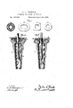
- Figure 1 is a detached view showing my elastic or yielding packing in a variety of shapes.
- Fig. 2 is a view, inlongitudinal section, of my packing as applied to a bung or stopper of a. barrel for containing liquid, showing my packing before it is compressed;
- Fig. 3 the same, showing the pack-' ing as compressed and in operation.
- A is my packing, constructed entirely or in part of yielding or elastic material, and shaped either annularly or in the fashion of a' hollow square, triangle, octagon, or any other desired figure, as shown or intimated in Fig. 1 of the drawings.
- my packing constitutes no essential part of my invention, as said shape should always be made to conform to the rod or tube designed to be surrounded by said packing; and of the seat or chamber in which it is to be used.
- This packing is made thick enough, so that, by pressure against one or both of its faces, its central opening will be diminished.
- B B represent the elements constituting a bung, the part B being the tapering body, and B an adjustable An opening through the cap B admits of the introduction of a draft-tube, G, which passes down through the central opening of the pack- B is exerting no pressure upon the packing
- the celitral opening of the packing willcap or top screwed into or upon the body B.
Landscapes
- Engineering & Computer Science (AREA)
- General Engineering & Computer Science (AREA)
- Mechanical Engineering (AREA)
- Gasket Seals (AREA)
Description
J. A. PRIN D L E. Packing for Rods 0r Tubes.
No. 214,841.- P-agen ted A ril 29,1879.-
QINV TOR I (LGAML 51 A WITNESSES UNITEDSTATES PATENT OFFIcE.
JOHN A. PRINDLE, OF CLEVELAND, OHIO.
IMPROVEMENT IN PACKING- FOR RODS OR TUBES.
Specification forming part of Letters Patent No. 214.841, dated April 29, 1879; application filed i J auuary 30, 1879. v
To all whom 'it may concern:
Be it known that I, JOHN A. PRINDLE, of Cleveland, in the county of Guyahoga and State of Ohio, have invented certain new and useful Improvements in Packing for Rods or Tubes; and I do hereby declare the following to be a full,clear, and exact description of the invention, such as will enable others skilled in the art to which it pertains to make and use it, reference being had to the accompanying drawings, which form part of this specification.
My invention relates to a packing especially adapted to prevent the escape of fluid or liquid between said packing and the rod or. tube passing through it; and it consists, broadly, in an annular, oval, square, or otherwise shaped elastic or yielding body of suitable material, such as rubber, leather, or equivalent substance, adapted, under pressure, to diminish its central opening; second, in an annular or otherwise shaped packing having an opening through it, and constructed from yielding or elastic material, adapted, by pressure, to diminish its opening, and to enlarge said opening when pressure is released; third, in the combination, with a packing, shaped annularly, or in the fashion of ahollow square, triangle, or other figure, of any suitable device for affording a seat or bearing-surface to either one or both of the faces of said packing; fourth, in the combination, with an elastic or yielding packing, shaped annularly, or in the fashion of a hollow square, triangle, or other shape, of a device affording to one or both faces of said packing a seat or bearing-surface. Said device maybe so adjustable as that the pressure upon said packing may be regulated as desired. a In the drawings, Figure 1 is a detached view showing my elastic or yielding packing in a variety of shapes. Fig. 2 is a view, inlongitudinal section, of my packing as applied to a bung or stopper of a. barrel for containing liquid, showing my packing before it is compressed; Fig. 3, the same, showing the pack-' ing as compressed and in operation.
While I do not limit the employment of my invention to any specific use, and therefore while not limiting myself to any specific form or construction of said device, I shall, for convenience, describe it as applicable to bungs or stoppers to be used in barrels containing effervescent or gaseous fluids through which a draft-tube is designed to be passed.
A is my packing, constructed entirely or in part of yielding or elastic material, and shaped either annularly or in the fashion of a' hollow square, triangle, octagon, or any other desired figure, as shown or intimated in Fig. 1 of the drawings.
The specific shape of my packing constitutes no essential part of my invention, as said shape should always be made to conform to the rod or tube designed to be surrounded by said packing; and of the seat or chamber in which it is to be used.
This packing is made thick enough, so that, by pressure against one or both of its faces, its central opening will be diminished.
justmeut of the valve is all that will ever be required; and in such cases, if found desirable, my packing may be'constructed simply for general purposes, I prefer that elasticity my packing, so that, when the pressure is rebe enlarged practically to its original dimen ,sions--at least sufficiently to loosen it from the tube or rod that it surrounds. When the packing A- is placed in a suitable seat or chamber, and pressure is brought to bear upon one or both of its faces, it will firmly and completely close upon any tubeor rod passing through its central opening in sugli a manner as to effectually prevent the escapeof fluid or liquid between said packing and tube.
As shown in Figs. 2 and 3, B B represent the elements constituting a bung, the part B being the tapering body, and B an adjustable An opening through the cap B admits of the introduction of a draft-tube, G, which passes down through the central opening of the pack- B is exerting no pressure upon the packing There may be instances where a singlead of yielding non-elastic material, although,
shall constitute one of the characteristics of,
leased, the celitral opening of the packing willcap or top screwed into or upon the body B.
A, and in this condition the central opening of said packing is sufliciently large to admit of the ready passage of the tube 0 through it; but when the cap B is screwed down, as shown in Fig. 3 of the drawings, in such a manner as to bring pressure upon the faces of the packing A, then the central opening of said packing A is diminished, and it now tightly embraces the tube 0 in such amanner as to effectually prevent any escape of fluid or liquid in this locality, while,'at the same time, on account of the elasticity or yielding character of the packing, escape of liquid or fluid is likewise prevented around its seat or bearing-surfaces.
Itwillbeevidentthat mypackingisadaptable to a great variety of devices-in fact, to any where the escape of fluid or liquid around a rod or tube is wished to be prevented; and any device will be comprehended by my invention that employs'an elastic or yielding packin g, shaped annularly, or in the fashion of a hollow square,
triangle, octagon, or other shape, and provided with any contrivance for exerting pressure upon one or both of. the faces of said packin g, whereby the diameter of its central opening may be regulated, as above specified.
Besides the abstract advantage as a packing that l have accomplished by my device, it possesses the additional recommendation of quick, easy, and reliableadjustm'ent.
If it is found thatthereis a leakage between the tube or rod 0 and its surrounding packing A, a slight adjustment of the. cap B, or its equivalent, whereby a little additional pressform,and a follower for subjecting'the packing to compression on one side thereof, whereby, the outer periphery of said packing being held against lateral expansion, the material thereof will be expanded inwardly and pack the rod located in the center of the packing, substantially as set forth; 7
In testimony whereof I have signed my name to this specificatiomin. the presence of two subscribing witnesses.
" JOHN A. PRINDLE. I
Witnesses JNo, ORowELL, J r.,
WILLARD FRAOKER.
Publications (1)
| Publication Number | Publication Date |
|---|---|
| US214841A true US214841A (en) | 1879-04-29 |
Family
ID=2284245
Family Applications (1)
| Application Number | Title | Priority Date | Filing Date |
|---|---|---|---|
| US214841D Expired - Lifetime US214841A (en) | Improvement in packing for rods or tubes |
Country Status (1)
| Country | Link |
|---|---|
| US (1) | US214841A (en) |
Cited By (3)
| Publication number | Priority date | Publication date | Assignee | Title |
|---|---|---|---|---|
| US2470540A (en) * | 1943-10-08 | 1949-05-17 | Mission Mfg Co | Protective sleeve for pump rods |
| US2822196A (en) * | 1955-04-25 | 1958-02-04 | Earl L Canfield | Pressure responsive distortable o-ring type waterproof seal |
| US2989075A (en) * | 1957-01-25 | 1961-06-20 | Johnston William Derrick | Valve |
-
0
- US US214841D patent/US214841A/en not_active Expired - Lifetime
Cited By (3)
| Publication number | Priority date | Publication date | Assignee | Title |
|---|---|---|---|---|
| US2470540A (en) * | 1943-10-08 | 1949-05-17 | Mission Mfg Co | Protective sleeve for pump rods |
| US2822196A (en) * | 1955-04-25 | 1958-02-04 | Earl L Canfield | Pressure responsive distortable o-ring type waterproof seal |
| US2989075A (en) * | 1957-01-25 | 1961-06-20 | Johnston William Derrick | Valve |
Similar Documents
| Publication | Publication Date | Title |
|---|---|---|
| US214841A (en) | Improvement in packing for rods or tubes | |
| US754618A (en) | Tapping device. | |
| US1986358A (en) | Check valve | |
| US156971A (en) | Improvement in combined bung and vent-valves | |
| US519513A (en) | Harry torchiani | |
| US825173A (en) | Apparatus for siphoning liquids from bottles. | |
| US327402A (en) | malmstrom | |
| US409288A (en) | Tap and bushing for barrels | |
| US298686A (en) | Petee gaednee | |
| US167049A (en) | Improvement in beer-faucets | |
| US447962A (en) | Lock-valve and faucet | |
| US280503A (en) | Stephen s | |
| US206825A (en) | Improvement in beer-pump valves | |
| US430349A (en) | Fruit-can | |
| US601749A (en) | Device for tapping beer-barrels | |
| US346558A (en) | John d | |
| US653034A (en) | Tapping device. | |
| US380782A (en) | Henry babrett and john j | |
| US439249A (en) | Adele michaux | |
| US185694A (en) | Improvement in bottle-stoppers | |
| US375076A (en) | James langstaff and samuel watson | |
| US393418A (en) | carlson | |
| US520239A (en) | Bushing and faucet for barrels | |
| US512036A (en) | Theodor klinghammer | |
| US397795A (en) | gates |