US213988A - Improvement in wind-engines - Google Patents
Improvement in wind-engines Download PDFInfo
- Publication number
- US213988A US213988A US213988DA US213988A US 213988 A US213988 A US 213988A US 213988D A US213988D A US 213988DA US 213988 A US213988 A US 213988A
- Authority
- US
- United States
- Prior art keywords
- wind
- shaft
- arm
- engines
- sails
- Prior art date
- Legal status (The legal status is an assumption and is not a legal conclusion. Google has not performed a legal analysis and makes no representation as to the accuracy of the status listed.)
- Expired - Lifetime
Links
- 230000006872 improvement Effects 0.000 title description 4
- 230000007246 mechanism Effects 0.000 description 7
- 210000003414 extremity Anatomy 0.000 description 5
- 238000005096 rolling process Methods 0.000 description 5
- 238000010276 construction Methods 0.000 description 3
- 210000003141 lower extremity Anatomy 0.000 description 2
- 206010016035 Face presentation Diseases 0.000 description 1
- 230000009471 action Effects 0.000 description 1
- 230000008901 benefit Effects 0.000 description 1
- 230000002939 deleterious effect Effects 0.000 description 1
- 230000004048 modification Effects 0.000 description 1
- 238000012986 modification Methods 0.000 description 1
- 230000001105 regulatory effect Effects 0.000 description 1
- 238000006467 substitution reaction Methods 0.000 description 1
- 210000001364 upper extremity Anatomy 0.000 description 1
Images

Classifications
-
- B—PERFORMING OPERATIONS; TRANSPORTING
- B64—AIRCRAFT; AVIATION; COSMONAUTICS
- B64C—AEROPLANES; HELICOPTERS
- B64C11/00—Propellers, e.g. of ducted type; Features common to propellers and rotors for rotorcraft
- B64C11/30—Blade pitch-changing mechanisms
- B64C11/32—Blade pitch-changing mechanisms mechanical
- B64C11/34—Blade pitch-changing mechanisms mechanical automatic
- B64C11/346—Blade pitch-changing mechanisms mechanical automatic actuated by the centrifugal force or the aerodynamic drag acting on auxiliary masses or surfaces
Definitions
- My invention relates to windmills, and is designed, first, to provide such a construction of the same that the angle of inclination of the sails to the wind may be regulated either by spring or weight mechanism, or by both; second, to permit the central post to have a very sensitive movement in its vertical rotation, whereby the wind may readily turn the sails into the eye of the wind; thirdly, to adapt the several sails to be independently adjusted 5 fourthly, to cause the sail-connecting mechanism with the head-plate to be prevented from all rolling motion, which injures and wears out the parts; and, fthly, to permit the rods which connect by link mechanism, respectively, with the head-plate and the several sails to have their pivoted bearings adjustable, so as to compensate for wear and take up all lost motion.
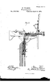
- Figure l is a view, in side elevation, of a mill embodying my invention.
- Fig. 2 is a front view of the same.
- Fig. 3 is a ⁇ view showin g part of the mill in sectional and part in side elevation.
- the tower A is provided with two horizontal arms, B and -(l,1whi ch may be formed in separate or single piece therewith.
- the central-post, D,- is formed with two annular shoulders, d and d, which fit, respectively, against the lower surface of the upper arm and the upper surface of the lower arm.
- the upper arm is provided with a metallic strip, b, which secures the post within the circular recess formed in the upper arn1,while the lower arm is provided with a box made in single or separate piece therefrom, through which the post passes, and upon which it has free vertical bearing in its rotary movement.
- a plunger, E has vertical movement, the lower extremity of which is connected by mechanism with the pumping-shaft, of such character as to permit said post to have its required vertical rotation, while it operates said shaft by its vertical movement.
- the upper extremity of the plunger may connect in any suitable manner with the main shaft, so as to be operated thereby. It is provided with a guide, F, which embraces opposite sides of the upright g of the forward wing, G, of the central post, and has vertical sliding movement thereon, so as to maintain the plunger in operative position.
- the sliding shaft H has longitudinal movement within the tubular main shaft J, and extends through the sam e. Its rear extremity is provided with a double bell-crank, K, the lower extremity of whose vertical arm is pivoted thereto, while the two horizontal arms extend, respectively, forward and rearward.
- the forward horizontal arm, K connects with a draw-cord or other suitable device, L, which passes downward, and is adapted to be operated to draw the sails in from too great a face presentation to the wind.
- This draw device may pass through the plunger when the latter is made tubular, as here shown, and in such instance a swinging loop, l, is placed immediately between the horizontal arm and said device.
- the rear horizontal arm, kl is provided with an adjustable weight, k2, of any suitable character, and operates to force the sliding rod outward through the tubular main shaft, and thereby set the sails squarely into the eye of the wind.
- Said sliding shaft is also provided with an annular shoulder, h, which provides outer end bearing for a spiral spring, M, which is fitted about the shaft, and which is held under pressure between said shoulder and the rear end of the tubular shaft.
- I thus represent the sliding shaft as being adapted to be forced outward either by spring mechanism, weight mechanism, or in part by both the two.
- weight and bell-crank device in whole or in part, consists in the ability to adjust the outward tendency of said sliding shaft as may be desired. Such adjustment is of valuable service, especially when used in mills whose main horizontal shaft actuates the plunger by means of mechanical gear-connection, such as bevel-gears, formed, respectively, on the engaging extremities of each of the same, in substitution for the link and eccentric connection shown in the drawings.
- My preferable manner of constructing a geared mill is to dispense with the rear horizontal arm of the bell-crank, and connect the free extremity of the forward arm of the latter by a rod or other rigid connection to a weighted lever placed at any suitable point below, said lever to be provided with an adjustable weight device, and in this way regulate the action ofthe mill.
- the head-plate N is provided with an annular series of holes, through which pass, respectively, the several links l, each of which latter has its outer extremity provided with nuts p, between which said head-plate is secured.
- the sails are independently adjustable, and the said nuts hold each of the connecting-links rigid and free from any tendency toward a rolling motion, which results in wear of the several parts.
- the rods 1t which connect each of the sails with the head-plate by means of links I and S, which engage respectively therewith, are formed rigid with rings T.
- Each of these rings has pivotal connection on opposite celltral sides thereof with bearing-plates t, which latter are secured to arms U of the wind-wheel, so as to take up all wear, and thus compensate for lost motion.
- said plates are respectively formed with longitudinal slots, which, in connection with set-screws, permit of said adjustment.
- a further prominent feature in the construction and the bearings of said rods It consists in their capacity to resist the strong tendency toward rolling motion, which is so objectionable in windmills and so deleterious to the several connecting parts. ln addition to these several devices for preventing said rolling motion, suitable springs may be employed, as shown.
- the combination with a tower provided with upper and lower horizontal arms, of a central post formed with annular shoulders which t, respectively, against the under surface of the upper arm and the upper surface of the lower arm, said post having an upward-projecting wing made in one piece therewith, which extends beneath the main horizontal shaft of the mill and provides bearin g for the same, substantially as set forth.
- a windmill the combination, with a tower provided with upper and lower horizontal arms, of a central post formed with annular shoulders which lit, respectively, against the under surface of the upper arm and the upper face of the lower arm, said upper arm being provided with a horizontally-curved recess, in which the post has lateral bearin g, and a fastening-strip to secure the same in place, while said lower arm is provided with a journal-box, in which the post has end bearing, substantially as set forth.
Landscapes
- Engineering & Computer Science (AREA)
- Physics & Mathematics (AREA)
- Fluid Mechanics (AREA)
- Mechanical Engineering (AREA)
- Aviation & Aerospace Engineering (AREA)
- Wind Motors (AREA)
Description
3 shee sheen 1..
N. HOLMES. ig
Wind-Engines.
Patented April 8, 13
` lNvENToR ATTORNEY INVENTOR N. HOLMES. Wind-Engines.
WITN ESSES @14 ATTORNEY 3 Sheets-Sheet 3. N HOLMES Wind-Engines No, 213,988. Patented Ap'ril 8,1879.
ATTORNEY ".PETERS. PHOYULITHOGRAFHER. WASKINGYON. D Cy NITED STATES PATENT FFIGE.
NELSON HOLMES, OF YPSILANTI, MICHIGAN, ASSIGNOR OF ONE-HALF HIS RIGHT TO HDISELF, SAMUEL W. PARSONS, AND GEORGE W. PARSONS:
OF SAME PLAGE.
IMPROVEMENT IN WIND-ENGINES.
Specification forming part of Letters Patent No. 213,988, dated April 8, 1879 application tiled September 2, 1878.
To all whom it may concern:
Be it known that I, NELSON HOLMES, of Ypsilanti, in the county of Washtenaw and State of Michigan, have invented certain new and useful Improvements in Windmills; and I do hereby declare the following to be a full, clear, and exact description of the invention, such as will enable others skilled in the art to which it pertains to make and use it, reference being had to the accompanying drawings, which form part of this specication.
My invention relates to windmills, and is designed, first, to provide such a construction of the same that the angle of inclination of the sails to the wind may be regulated either by spring or weight mechanism, or by both; second, to permit the central post to have a very sensitive movement in its vertical rotation, whereby the wind may readily turn the sails into the eye of the wind; thirdly, to adapt the several sails to be independently adjusted 5 fourthly, to cause the sail-connecting mechanism with the head-plate to be prevented from all rolling motion, which injures and wears out the parts; and, fthly, to permit the rods which connect by link mechanism, respectively, with the head-plate and the several sails to have their pivoted bearings adjustable, so as to compensate for wear and take up all lost motion.
ln the drawings, Figure l is a view, in side elevation, of a mill embodying my invention. Fig. 2 is a front view of the same. Fig. 3 is a` view showin g part of the mill in sectional and part in side elevation.
The tower A is provided with two horizontal arms, B and -(l,1whi ch may be formed in separate or single piece therewith. The central-post, D,- is formed with two annular shoulders, d and d, which fit, respectively, against the lower surface of the upper arm and the upper surface of the lower arm.
The upper arm is provided with a metallic strip, b, which secures the post within the circular recess formed in the upper arn1,while the lower arm is provided with a box made in single or separate piece therefrom, through which the post passes, and upon which it has free vertical bearing in its rotary movement.
Within this tubular post a plunger, E, has vertical movement, the lower extremity of which is connected by mechanism with the pumping-shaft, of such character as to permit said post to have its required vertical rotation, while it operates said shaft by its vertical movement.
The upper extremity of the plunger may connect in any suitable manner with the main shaft, so as to be operated thereby. It is provided with a guide, F, which embraces opposite sides of the upright g of the forward wing, G, of the central post, and has vertical sliding movement thereon, so as to maintain the plunger in operative position.
The sliding shaft H has longitudinal movement within the tubular main shaft J, and extends through the sam e. Its rear extremity is provided with a double bell-crank, K, the lower extremity of whose vertical arm is pivoted thereto, while the two horizontal arms extend, respectively, forward and rearward.
The forward horizontal arm, K, connects with a draw-cord or other suitable device, L, which passes downward, and is adapted to be operated to draw the sails in from too great a face presentation to the wind. This draw device may pass through the plunger when the latter is made tubular, as here shown, and in such instance a swinging loop, l, is placed immediately between the horizontal arm and said device.
The rear horizontal arm, kl, is provided with an adjustable weight, k2, of any suitable character, and operates to force the sliding rod outward through the tubular main shaft, and thereby set the sails squarely into the eye of the wind. Said sliding shaft is also provided with an annular shoulder, h, which provides outer end bearing for a spiral spring, M, which is fitted about the shaft, and which is held under pressure between said shoulder and the rear end of the tubular shaft. I thus represent the sliding shaft as being adapted to be forced outward either by spring mechanism, weight mechanism, or in part by both the two.
One advantage of using the weight and bell-crank device, in whole or in part, consists in the ability to adjust the outward tendency of said sliding shaft as may be desired. Such adjustment is of valuable service, especially when used in mills whose main horizontal shaft actuates the plunger by means of mechanical gear-connection, such as bevel-gears, formed, respectively, on the engaging extremities of each of the same, in substitution for the link and eccentric connection shown in the drawings.
My preferable manner of constructing a geared mill, however, is to dispense with the rear horizontal arm of the bell-crank, and connect the free extremity of the forward arm of the latter by a rod or other rigid connection to a weighted lever placed at any suitable point below, said lever to be provided with an adjustable weight device, and in this way regulate the action ofthe mill.
The head-plate N is provided with an annular series of holes, through which pass, respectively, the several links l, each of which latter has its outer extremity provided with nuts p, between which said head-plate is secured.
The sails are independently adjustable, and the said nuts hold each of the connecting-links rigid and free from any tendency toward a rolling motion, which results in wear of the several parts.
The rods 1t, which connect each of the sails with the head-plate by means of links I and S, which engage respectively therewith, are formed rigid with rings T. Each of these rings has pivotal connection on opposite celltral sides thereof with bearing-plates t, which latter are secured to arms U of the wind-wheel, so as to take up all wear, and thus compensate for lost motion. For this purpose said plates are respectively formed with longitudinal slots, which, in connection with set-screws, permit of said adjustment.
A further prominent feature in the construction and the bearings of said rods It consists in their capacity to resist the strong tendency toward rolling motion, which is so objectionable in windmills and so deleterious to the several connecting parts. ln addition to these several devices for preventing said rolling motion, suitable springs may be employed, as shown.
I do not enter into description of the remaining parts of the mill, as the same are not es sential to my invention, and are simply shown in the drawings in order to illustrate one form of operative mill with which my several improvements may be used.
As regards those parts which have been described, I would say that I am not confined to that exact construction, but various modifications of the same may be iliade.
Having fully described my invention, what I claim as new, and desire to secure by Letters Patent, is-
1. Inawindmill, the combination ofa tubular main shaft and an inner sliding shaft, the latter being provided with a springr and with a weighted bell-crank lever, both of which tend to force it forward, substantially as set forth.
2. In a windmill, the combination of a tubular main shaft and an inner sliding shaft, to the front end of which latter the sails are indirectly connected, said inner shaft being forwardly spring-pressed, and having its rear extremityengaging with a bellcrank lever, which is provided with a movable weight tending to force the shaft forward in any desired ad justment, substantially as set forth.
3. In a windmill, the combination, with a sliding shaft which passes through a main tu' bular shaft and is formed with a rear extension, of a bell-crank lever pivoted to the latter and provided with an adjustable weight device tending to force said sliding shaft forward, substantially as set forth.
4. In a windmill, the combination, with a tubular main shaft and a sliding shaft which passes through the same, of a double bell-crank pivoted to the rear extremity of said sliding shaft, the forward horizontal arm of the bellcrank being connected with a draw device, while the rear arm is provided with an adjustable weight device, substantially as set forth.
5. In a windmill, the combination, with a tubular central post formed with a forward win g, of a plunger provided with a guide having vertical sliding movement upon the upright arm of said win g, substantially as set forth.
6. In a windmill, the combination, with a tower provided with upper and lower horizontal arms, of a central post formed with annular shoulders which t, respectively, against the under surface of the upper arm and the upper surface of the lower arm, said post having an upward-projecting wing made in one piece therewith, which extends beneath the main horizontal shaft of the mill and provides bearin g for the same, substantially as set forth.
7. 1n a windmill, the combination, with a tower provided with upper and lower horizontal arms, of a central post formed with annular shoulders which lit, respectively, against the under surface of the upper arm and the upper face of the lower arm, said upper arm being provided with a horizontally-curved recess, in which the post has lateral bearin g, and a fastening-strip to secure the same in place, while said lower arm is provided with a journal-box, in which the post has end bearing, substantially as set forth.
8. In a windmill, the combination, with a sliding head-plate and a sail, of rod and link mechanism which connects the two. said rod being provided with bearings, which connect it to the wheel-arms in pivotal movement and prevent any rolling movement thereof, substantially as set forth.
9. In a windmill, the combination, with a head-plate, of sail-connecting links which engage therewith and permit of the relative adjustment of the several sails independently of each other, substantially as set forth.
10. In a windmill, the combination, with a l MILW- pivoted links connecting, respectively, with a Sail and a head-plate, of a ring-piece formed rigid therewith, and whose opposite sides have pivotal connection with adjustable bearing-plates secured to the wheel-arms, substantially as set-forth.
In testimony that I claim the foregoing I have hereunto set my hand and seal this 27th (lay of August, 1878.
NELSON HOLMES. [L s] In presence of- J oHN S. HARRIS, L. W. MILLER.
Publications (1)
| Publication Number | Publication Date |
|---|---|
| US213988A true US213988A (en) | 1879-04-08 |
Family
ID=2283392
Family Applications (1)
| Application Number | Title | Priority Date | Filing Date |
|---|---|---|---|
| US213988D Expired - Lifetime US213988A (en) | Improvement in wind-engines |
Country Status (1)
| Country | Link |
|---|---|
| US (1) | US213988A (en) |
-
0
- US US213988D patent/US213988A/en not_active Expired - Lifetime
Similar Documents
| Publication | Publication Date | Title |
|---|---|---|
| US213988A (en) | Improvement in wind-engines | |
| US178507A (en) | William t | |
| US1555349A (en) | Windmill pump | |
| US469786A (en) | Wind-wheel | |
| US230928A (en) | Windmill | |
| US389192A (en) | Leonaed e | |
| US988098A (en) | Windmill. | |
| US622115A (en) | Windmill | |
| US305114A (en) | Wind-engine | |
| US726376A (en) | Windmill. | |
| US553230A (en) | Windmill | |
| US192668A (en) | Improvement in windmills | |
| US234204A (en) | Windmill | |
| US188743A (en) | Improvement in windmills | |
| US114381A (en) | Improvement in wind-wheels | |
| US1093881A (en) | Wind-wheel. | |
| US408422A (en) | Signors to the mast | |
| US132060A (en) | Improvement in windmills | |
| USRE9493E (en) | William h | |
| US130071A (en) | Improvement in wind-wheels | |
| US367405A (en) | jonasson | |
| US88407A (en) | Improvement in wind-wheels | |
| US147067A (en) | Improvement in windmills | |
| US413567A (en) | Windmill | |
| US128577A (en) | Improvement in windmills |