US2139804A - Fuel feeding system for internal combustion engines - Google Patents
Fuel feeding system for internal combustion engines Download PDFInfo
- Publication number
- US2139804A US2139804A US680838A US68083833A US2139804A US 2139804 A US2139804 A US 2139804A US 680838 A US680838 A US 680838A US 68083833 A US68083833 A US 68083833A US 2139804 A US2139804 A US 2139804A
- Authority
- US
- United States
- Prior art keywords
- fuel
- air
- nozzle
- spray
- passage
- Prior art date
- Legal status (The legal status is an assumption and is not a legal conclusion. Google has not performed a legal analysis and makes no representation as to the accuracy of the status listed.)
- Expired - Lifetime
Links
Images

Classifications
-
- F—MECHANICAL ENGINEERING; LIGHTING; HEATING; WEAPONS; BLASTING
- F02—COMBUSTION ENGINES; HOT-GAS OR COMBUSTION-PRODUCT ENGINE PLANTS
- F02M—SUPPLYING COMBUSTION ENGINES IN GENERAL WITH COMBUSTIBLE MIXTURES OR CONSTITUENTS THEREOF
- F02M61/00—Fuel-injectors not provided for in groups F02M39/00 - F02M57/00 or F02M67/00
-
- F—MECHANICAL ENGINEERING; LIGHTING; HEATING; WEAPONS; BLASTING
- F02—COMBUSTION ENGINES; HOT-GAS OR COMBUSTION-PRODUCT ENGINE PLANTS
- F02M—SUPPLYING COMBUSTION ENGINES IN GENERAL WITH COMBUSTIBLE MIXTURES OR CONSTITUENTS THEREOF
- F02M69/00—Low-pressure fuel-injection apparatus ; Apparatus with both continuous and intermittent injection; Apparatus injecting different types of fuel
- F02M69/04—Injectors peculiar thereto
-
- F—MECHANICAL ENGINEERING; LIGHTING; HEATING; WEAPONS; BLASTING
- F02—COMBUSTION ENGINES; HOT-GAS OR COMBUSTION-PRODUCT ENGINE PLANTS
- F02M—SUPPLYING COMBUSTION ENGINES IN GENERAL WITH COMBUSTIBLE MIXTURES OR CONSTITUENTS THEREOF
- F02M2700/00—Supplying, feeding or preparing air, fuel, fuel air mixtures or auxiliary fluids for a combustion engine; Use of exhaust gas; Compressors for piston engines
- F02M2700/07—Nozzles and injectors with controllable fuel supply
Definitions
- the invention relates generally to a fuel feeding system for an internal combustion engine, in which individual metered charges of fuel are injected under pressure, and more particularly to a fuel discharge nozzle for such a system.
- One object of the invention is to provide a pressure discharge nozzle of novel and improved construction particularly adapted to discharge fuel in an annular spray across or counter to the flow of air past the nozzle into the cylinders of the engine.
- Another object is to provide a nozzle which discharges fuel in an annular spray generally laterally of the nozzle and the passage in which 5 the nozzle is disposed and in which the energy of the spray is utilized to distintegrate the spray.
- Yet another object is to provide a novel and improved nozzle having means for discharging an annular spray generally laterally of the nozzle and means utilizing the energy of the spray to create an aspirating effect establishing air jets or currents impinging against the spray at right angles to disintegrate the spray and to prevent the spray from striking the walls of the passage in which the nozzle is disposed.
- Still another object is to provide a nozzletermlnating in a head having an annular valve seat and an annular groove circumscribing the valve seat, a yleldable valve adapted to engage the seat, and opened by pressure within the nozzle to permit of an annular and lateral spray discharge, and a cap having an annular flange disposed opposite the groove to form therewith a zig-zag passage and air passages providing jets of air impinging against the spray in the zig-zag passage further to disintegrate the same.
- a further object is to provide a nozzle of the character described having a fixed restriction in the fuel supply passage to the valve of the nozzle to prevent ramming of the fuel in the passa e toward the valve at the end of the delivery period.
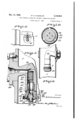
- Figure 1 is a side elevation of an internal combustion engine showing the application of my lin proved construction of fuel feeding system thereto;
- Figure 2 is a transverse sectional view of a portion of an internal combustion engine cylinder illustrating the manner in which the nozzle discharges its fuel into the air passageway leading into the cylinders;
- Figure 3 is an enlarged section through one form of nozzle used in connection with the fuel feeding system
- Figure 4 is a detail view illustrating a means for driving the pump of the fuel feeding system from the cam shaft of the engine;
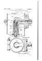
- Figure 5 is an enlarged longitudinal section through another form of nozzle to be used with the fuel feeding system
- Figure 6 is a section taken on line 6-43 of Figure 5;
- Figure 7 is a vertical longitudinal section through another form of nozzle
- Figure 8 is a horizontal section through the air inlet pipe showing the nozzle in plan view
- Figure 9 is a detail section through the air inlet showing the nozzle in elevation in position therein to deliver a spray of fuel against the air passing therethrough.
- A indicates an internal com bustion engine of the four cylinder, four cycle type having the usual crank shaft B which is adapted to drive the cam shaft C in the usual manner.
- the cam shaft C carries a WormDwhich meshes with a worm wheel E adapted to drive the pump shaft of the pump F herein shown constructed substantially in the same manner as disclosed in my application Serial No. 290,492, filed July 5, 1928.
- the pump F receives its fuel from a source of supply G through a pipe H and is constructed to deliver fuel through outlet pipes I into the respective air passages J leading to the respective cylinders of the engine, each of said air passages being controlled by a valve K operated by the cam shaft in the usual manner.
- the type of pump as shown is of the variable output type having variable stroke pistons and is substantially the same as shown in the above referred to application, the same being provided with control means L for increasing or decreasing the stroke of the pistons and while I have shown my fuel feeding system used in connection with this particular type of pump, I am aware that it can be used in connection with other types of pumps which are provided with vmeans for metering and delivering measured charges of fuel to the air inlet passages of the internal combustion engines.
- the four cylinder type of engine herein shown is'provided with an air intake manifold M provided with branches connected respectively with in the above referred to application whereby the proper proportion of fuel to air will be delivered to the cylinders of the engine.
- the nozzles are so constructed and positioned within the air inlet of the engine that I am able to utilize the energy of the fuel to produce an aspirating effect on the air in order to cause the air to penetrate the sheet of fuel sprayed from the nozzle and while certain types have proven more satisfactory-to certain types of engines, the other types shown have many advantages when used in connection with other types of engines and therefore I do not wish to limit myself to the use of any particular construction of nozzle for manifold as my invention consists broadly in providing a nozzle which delivers a sheet of fuel either against the flow of air passing through the air inlet or across the flow of air passing through said air inlet which energy is used to disintegrate the film or sheet of fuel and fuel under pressure is discharged laterally and downwardly in the air passage against the stream of air passing therethrough.
- FIG. 2 and 3 I show the wall of. the air passage J apertures to receive the nozzle herein designated l and shown right angular in form having a fuel inlet passage 2 communicating with a chamber 3 in which is arranged a strainer 4 carried by a plug 5 threaded within the lower which the fuel passes into the annular chamber ll of the head.
- the end of the tube terminates ean be adjusted in respect to its seat by operin a solid portion l2 which is threaded and on which is mounted a cap l3 which carries a washer ll which engages a laminated valve l5 formed of a plurality of flexible discs gradually decreasing in size and constructed substantially the same ating the cap I3.
- the cap- I3 is provided with air inlets l1 and the upper edge thereof is annular1y-reduced so that a zig-zag passageway is formed between the freeends of the flexible discs and the outer face of the head whereby air drawn in through the air inlets H by the energy of the fuel discharged will first penetrate the film of fuel being discharged therefrom and then repenetrate the fllm so as to thoroughly break up the sheet and prevent it from being sprayed against the inner wall of the manifold.
- the horizontal portion of the nozzle l. is clamped in position within the air intake manifold by clamping means 18 whereby novel means are provided for securing the nozzle in position within the air intake so that it can be readily inserted or removed.
- the fuel passage 2 is adapted to be connected to one of the outlet pipes I of the pump whereby metered charges of fuel will be delivered into the air passage which charges are timed by the engine.
- the nozzle is extended downwardly into the air passage so that the fuel discharged therefrom is against the flow of air and as the fuel is being discharged under pressure in an annular sheet or film, it produces an aspirating effect which causes air to bedrawn through the openings I1 and to penetrate the film being discharged from the periphery of the valve and after penetrating this film or sheet, it again penetrates this film or sheet before the sheet discharges from the periphery of the nozzle thereby breaking up the spray in order to produce a homogeneous mixture.
- a zig-zag passage Z is formed annularly by the construction of head and cap and as the walls of this passage are beveled, it has the tendency to such in air through the air inlet H which action is augmented by the natural flow of air through the air intake pipe and also by the increase in velocity in the pipe at the point opposite this aspirating head whereby the air penetrates the film in an upward movement first and then penetrates the film in a downward movement in traveling through the zig-zag passage so as to break up the film of fuel whereby a very finely divided mixture is delivered from the nozzle which will be readily picked up by the main air flowing therethrough.
- the nozzle l9 herein shown is also adapted to be inserted through an opening in the wall of the air intake and secured in position by suitable clamping means 20.
- the nozzle comprises a horizontally disposed portion similar to that disclosed in Figures 2 and 3 and a depending portion similar to that disclosed in Figures 2 and 3 with a fuel chamber 2
- the head 21 is provided with a fuel chamber 3
- the head 21 is annularly reduced and carries a ring'38 which is provided with arc-shaped slots 39 which communicate with annular grooves 40 formed in the under surface of the ring as shown in Figure 6 whereby the energy of the fuel discharged from the nozzle at low speed is utilized to cause air to be drawn down through the slots 39 as shown by the arrow X (Fig. 5) and to penetrate the film of fuel being discharged therefrom.
- the annular sheet or film sprayed from the nozzle is penetrated by the air being sucked through the semi-circular slots so as to prevent it from being sprayed against the wall and to allow it to thoroughly mix with the air in its passage to the cylinder of the engine.
- a nozzle constructed as shown in Figures 5 and 6 when used in connection with a fuel feeding system as disclosed in Figure 1 is as follows As the fuel is delivered in measured charges to the respective air intakes through the pipes I from the pump which is driven and timed by the engine through the medium of the restriction formed in the washer, the fuel is retained in a-full amount in the passage leading from the pump so as to prevent or reduce the tendency of the column of fuel contained in the tube from oscillating whereby surging of the fuel is prevented and I am able to deliver accurate measured charges of fuel into the air stream in a finely divided spray which will be picked up by the air flowing to the respective cylinders of the engine.
- the flexible valve opens to deliver a measured charge of fuel, if the engine is idling, the energy of this fuel which is delivered in an an nular sheet or spray produces an aspirating effect inasmuch as it causes air to be drawn down through the slots 39 and to penetrate the film in order to break it up so as to prevent it from impinging against the inner walls of the manifold.
- the air pipe J is apertured and surrounding this pipe is a split ring member 4
- the nipple 44 communicates with a horizontally disposed fuel duct 45 which in turn communicates with a chamber 46 formed in the (ill depending portion of the nozzle.
- the lower end of the chamber is threaded and has secured therein a head 41 constructed substantially in the same manner as disclosed in Figures 5 and 6, said head having its neck portion internally threaded to receive the stem 48 which is provided with a fuel passage 49 restricted at 50 and communicating with a transverse passage 5
- This stem is located within a circular strainer 52 which is held in place by the head 53, a screw bolt 54 working in a threaded socket formed in the upper end of the stem as clearly shown.
- This provides a novel construction of strainer and restriction for filtering the fuel and for eliminating the surging or ramming effect.
- the lower end of the strainer is preferably seated against a packing ring so that in assembling a tight joint is produced and the strainer is prevented from being injured.
- the circular strainer 52 is formed of a tubular body provided with slots over which is wound a wire to form a straining element.
- the head 41 carries a ring K provided with slots K substantially as shown in the embodiment of my invention as illustrated in Figures 5 and 6.
- my invention consists of a fuel feeding system of this nature wherein there is a cooperation between all of the parts of the fuel feeding system and the internal combustion engine, I wish it to be understood that my invention consists broadly in providing a fuel feeding system with a nozzle which utilizes the energy of the fuel being discharged therefrom to produce an aspirating effect to break up the annular spray of fuel.
- a direct fuel injecting system in which a fuel metering and distributing pump is employed which checks the fuel after measuring each charge and forces it under pressure through a spray nozzle into an air intake pipe in the form of an annular spray against the stream of air passing therethrough so as to reduce the size of the fuel droplets by mechanical atomization whereby the evaporation will be more rapid because of the increased surface exposed to the pulverizing action of the air to form a preliminary homogeneous mixture without the use of heat whereby all cylinders of the engine are maintained at a uniform temperature due to the more perfect distribution of the explosive mixture to the respective cylinders of the engine which obtains a thorough burning of the charge which increases the power.
- a nozzle for pressure fuel feeding systems for internal combustion engines having means for discharging 'an annular spray of fuel therefrom under pressure including a valve seat and a valve yieldably urged to seated position and adapted to be opened by the pressure of the fuel to bedischarged, and means for utilizing the energy of said spray for causing air to penetrate and disintegrate said spray.
- a nozzle for a pressure fuel feeding system for internal combustion engines comprising a valve seat, a flexible valve normally seated and adapted to be opened by the. pressure of the fuel for allowing fuel to be discharged therefrom in an annular spray, said nozzle having air passages for utilizing the energy of the spray to cause air to penetrate the spray discharged therefrom.
- a nozzle for feeding fuel under pressure to fuel feeding systems for internal combustion enginss having an annular vave seat, a flexible disc valve mounted thereon and adapted to open under the pressure of the fuel, said valve being surrounded by an annular groove, a cap having air inlets and an annular projection extending into said groove to form a zig-zag passageway through which the spray of fuel is adapted to pass, the
- a nozzle for fuel feeding means for internal combustion engines adapted to deliver an annular spray of fuel under pressure against the air stream passing to the engine, comprising a head providing a valve seat, a normally closed valve yieldably urged to seated position and opened only by the pressure of the fuel to be discharged, and slots in the head through which air is adapted to be drawn by the energy of the fuel passing through said nozzle for breaking up the annular spray of fuel in its discharge therefrom.
- a nozzle of the kind described comprising a body having an annular valve seat, a flexible valve mounted on said seat, means for adjusting the tension of said valve, said body having an fuel is adapted to be forced under pressure, a-7
- a nozzle for a pressure discharge fuel feeding system for internal combustion engines comprising means for discharging a spray of fuel therefrom under pressure including a valve seat and a normally closed valve yieldably urged to seated position and adapted to be opened by the pressure of the fuel to be discharged, and aspirator-like means utilizing the energy of said spray for creating air currents impinging against the spray to disintegrate the same.
- a nozzle for a pressure fuel feeding system for internal combustion engines comprising means for discharging an annular spray of fuel under pressure including an annular valve seat and a normally closed valve yieldably urged to closed position and opened only by the pressure of the fuel to be discharged, and means providing air passages extending generally transversely of the annular spray and rendering effective the energy of said spray for drawing air through said passages and impinging the same against said annular spray to disintegrate the .same.
- a nozzle for a pressure fuel feeding system for internal combustion engines comprising a tubular body portion having an annular valve seat, a valve yieldably mounted on said seat to permit opening of the valve and discharge of fuel under pressure in a generally radial spray. and air passages in said body portion extending generally axially thereof and adjacent the edge of said valve to utilize the energy of said spray for creating air currents impinging against the spray to disintegrate the same.
- a nozzle for a pressure discharge, fuel feeding system for internal combustion engines comprising a tubular body having an annular valve seat, a fuel passage within said body terminating in an annular chamber, a flexible disk valve mounted on said seat opened by pressure to perrnit of a generally lateral spray discharge of fuel, and air passages in said body extending generally longitudinally thereof and adjacent the edge of said valve to utilize the energy of said spray for creating air currents impinging against said spray to disintegrate the same.
- a nozzle for a pressure discharge. fuel feeding system comprising a tubular body providing an annular valve seat, a valve yieldably mounted on said seat to permit of a generally lateral spray discharge of fuel, said body having an annular passage zig-zag in cross section through which the discharge takes place, and generally longitudinal air inlet passages discharging into said annular zig-zag passage.
- a nozzle for a pressure fuel feeding system comprising a tubular body terminating in an annular valve seat and an annular recess surrounding the seat, a flexible valve mounted on said seat to permit of a generally lateral spray discharge of fuel under pressure, and a cap securing said valve against said seat and having an end edge projecting into said annular recess to provide a passage zig-zag in cross section, said cap having air passages extending generally longitudinally therethrough and terminating at the edge of said valve whereby the spray discharge draws air through the passages and into said zig-zag passage.
- a nozzle for a pressure fuel feeding system for an internal combustion engine, comprising a portion having a fuel inlet passage, a tubular body portion having a chamber communicating with said fuel inlet passage, a plug threaded into said tubular portion terminating in an enlarged head, a tubular member threaded within said plug having an end projecting from said plug and a passageway communicating at one end with the chamber and terminating at the other end in restricted radial passages, a strainer in said chamber interposed between the passage in said tubular member and the fuel inlet passage, an innular flange formed on said head providing a valve seat, an annular recess surrounding said valve seat, a flexible disk valve mounted on the projecting end of said tubular member and cooperating with said seat, and a cap threaded onto the tubular member to retain said valve in position and having an annular end edge disposed opposite the annular groove in said head to form therewith-a zig-zag passage, and inlet passages leading from the exposed end of the cap and discharging
- a nozzle for a pressure fuel feeding system for an internal combustion engine comprising a portion having a fuel inlet passage, a tubular body portion having a chamber communicating with said fuel inlet passage, a plug threaded into said tubular portion terminating in an enlarged head, a tubular member located in the chamber and threaded into the threaded portion of said plug, said head having passages therein communicating with the chamber through said tubular member and terminating in an annular recess in the outer face of the head, a washer remov-- ably interposed between said plug and said tubular member providing a restriction in the passage through the nozzle, a flexible disk valve mounted on the end of said head to control the discharge of fuel therefrom, and an annular flange formed on said head outwardly of the edge of said valve and having arcuate slots extending longitudinally therethrough.
- a nozzle for a pressure discharge, fuel feeding system for internal combustion engines comprising a body portion having a chamber therein, an inlet passage leading to the chamber, a discharge passage leading from the chamber, a valve controlling the discharge passage, and a strainer positioned in the chamber interposed between the inlet and the discharge passage.
- a nozzle for a pressure fuel feeding system having an intake passage through which air flows, comprising a tubular body portion adapted to extend longitudinally of the passage, means including a yieldably mounted pressure actuated valve for producing a spray discharge directed generally laterally and counter to the direction of air flow through the passage, and means utilizing the energy of the spray discharge for creating air currents impinging against the spray operating with the air flow through the passage to disintegrate the spray and prevent the same from striking the walls of the intake passage.
- a nozzle for a pressure discharge, fuel feeding system having an air supply passage, comprising a tubular body portion terminating in a discharge head pointing in a direction oposed to the air flow through the passage, means in the head including an annular valve seat and a yieldable valve for producing an annular generally lateral spray discharge, and apertures in the head disposed to utilize the energy of the spray discharge for producing an aspirating effect creating air currents penetrating the spray discharge to disintegrate the same.
- a nozzle for a pressure discharge, fuel feeding system having a passage through which air flows, comprising a tubular body portion terminating in a, head pointing in a direction counted to the direction of air flow through the passage,
- means in the head including an annular valve seat and a yieldable valve for producing an annular generally lateral spray discharge, an annular passage of zig-zag shape in cross section formed in the head through which the spray is discharged, and air inlet passages opening through the end of the head and discharging into said CE TI Patent No. 2,159,80L
- FIGA'I'E OF CORRECTION is a diagrammatic representation of FIGA'I'E OF CORRECTION.
- a nozzle for a fuelfeeding system for an internal combustion engine having an air intake passage comprising a tubular body portion disposed iongitudinally of the passage, said body portion terminating at one end in an enlarged head substantially reducing the area of the air passage and gradually tapering from the head to terminate in a smoothly curved end, said portion being disposed with the head directed counter to the direction of air flow through the passage, means for efiecting an annular spray discharge from the head, and means formed in the head for utilizing the energy of the discharge to create air currents impinging against the annular discharge to disintegrate the same.
Landscapes
- Engineering & Computer Science (AREA)
- Chemical & Material Sciences (AREA)
- Combustion & Propulsion (AREA)
- Mechanical Engineering (AREA)
- General Engineering & Computer Science (AREA)
- Fuel-Injection Apparatus (AREA)
Description
'1938. M. G. CHANDLER 2,139,804
FUEL FEEDING SYSTEM FOR INTERNAL COMBUSTION ENGINES Filed July 17, 1933 3 SheetsSheet 1 Dec. 13, 1938. M. G. CHANDLER 2,139,804
FUEL FEEDING SYSTEM FOR INTERNAL COMBUSTION ENGINES Filed July 17, 1933 3 Sheets-Sheet 2 I I W'6 I r 2 36(2). Z, v I
Dec. 13, 1938. M, G, CHANDLER 2,139,804
FUEL FEEDING SYSTEM FOR INTERNAL COMBUSTION ENGINES Filed July 17, 1933 5 Sheets-Sheet 3 M u m w Patented Dec. 13, 1938 PATENT OFFICE FUEL FEEDING SYSTEM FOR. INTERNAL COMBUSTION ENGINES Milford G. Chandler, Flint, Diicln, assignor, by
mesne assignments, to Borg-Warner Corporation, Chicago, 111., a corporation of Illinois Application July 17, 1933, Serial No. 680,838
19 Claims.
The invention relates generally to a fuel feeding system for an internal combustion engine, in which individual metered charges of fuel are injected under pressure, and more particularly to a fuel discharge nozzle for such a system.
One object of the invention is to provide a pressure discharge nozzle of novel and improved construction particularly adapted to discharge fuel in an annular spray across or counter to the flow of air past the nozzle into the cylinders of the engine.
Another object is to provide a nozzle which discharges fuel in an annular spray generally laterally of the nozzle and the passage in which 5 the nozzle is disposed and in which the energy of the spray is utilized to distintegrate the spray.
Yet another object is to provide a novel and improved nozzle having means for discharging an annular spray generally laterally of the nozzle and means utilizing the energy of the spray to create an aspirating effect establishing air jets or currents impinging against the spray at right angles to disintegrate the spray and to prevent the spray from striking the walls of the passage in which the nozzle is disposed.
Still another object is to provide a nozzletermlnating in a head having an annular valve seat and an annular groove circumscribing the valve seat, a yleldable valve adapted to engage the seat, and opened by pressure within the nozzle to permit of an annular and lateral spray discharge, and a cap having an annular flange disposed opposite the groove to form therewith a zig-zag passage and air passages providing jets of air impinging against the spray in the zig-zag passage further to disintegrate the same.
A further object is to provide a nozzle of the character described having a fixed restriction in the fuel supply passage to the valve of the nozzle to prevent ramming of the fuel in the passa e toward the valve at the end of the delivery period.
Other and ancillary objects and advantages will become apparent from one following detailed description and the drawings.
In the drawings,
Figure 1 is a side elevation of an internal combustion engine showing the application of my lin proved construction of fuel feeding system thereto;
Figure 2 is a transverse sectional view of a portion of an internal combustion engine cylinder illustrating the manner in which the nozzle discharges its fuel into the air passageway leading into the cylinders;
55 Figure 3 is an enlarged section through one form of nozzle used in connection with the fuel feeding system;
Figure 4 is a detail view illustrating a means for driving the pump of the fuel feeding system from the cam shaft of the engine;
Figure 5 is an enlarged longitudinal section through another form of nozzle to be used with the fuel feeding system;
,Figure 6 is a section taken on line 6-43 of Figure 5;
Figure 7 is a vertical longitudinal section through another form of nozzle;
Figure 8 is a horizontal section through the air inlet pipe showing the nozzle in plan view; and
Figure 9 is a detail section through the air inlet showing the nozzle in elevation in position therein to deliver a spray of fuel against the air passing therethrough.
In illustrating my improved construction of fuel feeding system for internal combustion engines, I have shown the same used in connection with a certain type of engine to enable one skilled in the art to readily understand the operation of the same but it is, of course, understood that I do not Wish to limit myself to the use of any particular type of engine or to any particular type of pump so long as the pump is constructed to deliver metered individual charges of fuel for servicing the respective cylinders of the engine.
In the drawings A indicates an internal com bustion engine of the four cylinder, four cycle type having the usual crank shaft B which is adapted to drive the cam shaft C in the usual manner. The cam shaft C carries a WormDwhich meshes with a worm wheel E adapted to drive the pump shaft of the pump F herein shown constructed substantially in the same manner as disclosed in my application Serial No. 290,492, filed July 5, 1928. The pump F receives its fuel from a source of supply G through a pipe H and is constructed to deliver fuel through outlet pipes I into the respective air passages J leading to the respective cylinders of the engine, each of said air passages being controlled by a valve K operated by the cam shaft in the usual manner.
The type of pump as shown is of the variable output type having variable stroke pistons and is substantially the same as shown in the above referred to application, the same being provided with control means L for increasing or decreasing the stroke of the pistons and while I have shown my fuel feeding system used in connection with this particular type of pump, I am aware that it can be used in connection with other types of pumps which are provided with vmeans for metering and delivering measured charges of fuel to the air inlet passages of the internal combustion engines.
The four cylinder type of engine herein shown is'provided with an air intake manifold M provided with branches connected respectively with in the above referred to application whereby the proper proportion of fuel to air will be delivered to the cylinders of the engine.
In all ofthe embodiments of my invention as hereinafter fully shown and described, the nozzles are so constructed and positioned within the air inlet of the engine that I am able to utilize the energy of the fuel to produce an aspirating effect on the air in order to cause the air to penetrate the sheet of fuel sprayed from the nozzle and while certain types have proven more satisfactory-to certain types of engines, the other types shown have many advantages when used in connection with other types of engines and therefore I do not wish to limit myself to the use of any particular construction of nozzle for manifold as my invention consists broadly in providing a nozzle which delivers a sheet of fuel either against the flow of air passing through the air inlet or across the flow of air passing through said air inlet which energy is used to disintegrate the film or sheet of fuel and fuel under pressure is discharged laterally and downwardly in the air passage against the stream of air passing therethrough.-
vIn the embodiment of my invention as shown in Figures 2 and 3 I show the wall of. the air passage J apertures to receive the nozzle herein designated l and shown right angular in form having a fuel inlet passage 2 communicating with a chamber 3 in which is arranged a strainer 4 carried by a plug 5 threaded within the lower which the fuel passes into the annular chamber ll of the head. The end of the tube terminates ean be adjusted in respect to its seat by operin a solid portion l2 which is threaded and on which is mounted a cap l3 which carries a washer ll which engages a laminated valve l5 formed of a plurality of flexible discs gradually decreasing in size and constructed substantially the same ating the cap I3. The cap- I3 is provided with air inlets l1 and the upper edge thereof is annular1y-reduced so that a zig-zag passageway is formed between the freeends of the flexible discs and the outer face of the head whereby air drawn in through the air inlets H by the energy of the fuel discharged will first penetrate the film of fuel being discharged therefrom and then repenetrate the fllm so as to thoroughly break up the sheet and prevent it from being sprayed against the inner wall of the manifold.
The horizontal portion of the nozzle l. is clamped in position within the air intake manifold by clamping means 18 whereby novel means are provided for securing the nozzle in position within the air intake so that it can be readily inserted or removed. The fuel passage 2 is adapted to be connected to one of the outlet pipes I of the pump whereby metered charges of fuel will be delivered into the air passage which charges are timed by the engine.
In the operation of a fuel feeding system as disclosed with a fuel nozzle constructed as illustrated in Figures 2 and 3 and used in connection with a fuel feeding-system as disclosed in Figure l, the operation is as follows: When the engine is in operation, suction is produced by the piston displacement in order to cause air to be drawn through the air passages and whether the velocity of this air is increased by other mechanical means or not, the. air moves past the nozzle and as the nozzle is disposed in the air inlet and of such a size that'the enlarged head thereof forms more or less a restriction, naturally the velocity of air passing said head is increased.
In this construction the nozzle is extended downwardly into the air passage so that the fuel discharged therefrom is against the flow of air and as the fuel is being discharged under pressure in an annular sheet or film, it produces an aspirating effect which causes air to bedrawn through the openings I1 and to penetrate the film being discharged from the periphery of the valve and after penetrating this film or sheet, it again penetrates this film or sheet before the sheet discharges from the periphery of the nozzle thereby breaking up the spray in order to produce a homogeneous mixture.
It will be noted that a zig-zag passage Z is formed annularly by the construction of head and cap and as the walls of this passage are beveled, it has the tendency to such in air through the air inlet H which action is augmented by the natural flow of air through the air intake pipe and also by the increase in velocity in the pipe at the point opposite this aspirating head whereby the air penetrates the film in an upward movement first and then penetrates the film in a downward movement in traveling through the zig-zag passage so as to break up the film of fuel whereby a very finely divided mixture is delivered from the nozzle which will be readily picked up by the main air flowing therethrough.
As the fuel is being discharged intermittently from the nozzle in measured charges and as the energy of the fuel is used to cause an aspirating effect to produce a breaking up of the film or sheet, I am able to produce a fuel feeding system wherein ,the fuel is thoroughly mixed with the air before it is delivered to the cylinders of the engine.
By having the fixed restriction so as tomain-' tendency of the column of fuel contained in the with a fuel feeding system as illustrated in Figure 1, I have provided a construction to overcome the tendency of the fuel to deposit upon the surface when said flow is very slow, for instance while idling.
The nozzle l9 herein shown is also adapted to be inserted through an opening in the wall of the air intake and secured in position by suitable clamping means 20. The nozzle comprises a horizontally disposed portion similar to that disclosed in Figures 2 and 3 and a depending portion similar to that disclosed in Figures 2 and 3 with a fuel chamber 2| which is in communication with the fuel inlet 22 of the horizontal portion and in which is mounted a strainer 23 carried bya plug 24 provided with a reduced threaded end 25 which in turn is threaded into the internally threaded neck 26 of a head 21 which is threaded into the lower end of the chamber 2|, said head carrying a washer 28 secured in position by the plug 24 and provided with a restricted opening 29 which prevents the surging of the fuel and it will be seen that this washer 28 is removable so that washers of different calibrated openings can be substituted for one another if desired.
The head 21 is provided with a fuel chamber 3|! below the washer 28 from which extend fuel passages 3i which terminate in an annular chamber 32 closed by a laminated flexible valve 33 composed'of a series of flexible discs gradually decreasing in size which are arranged on a stem 34 against a washer 35 and are secured in position by a nut 36 so that these flexible discs are anchored at their center and the larger disc engages a valve seat 3'l surrounding chamber 32.
This provides a construction whereina nozzle is formed with a flexible valve anchored at its center in a similar manner to that disclosed in application Serial No. 421,558 whereby the tension of the disc on the seat can be adjusted by substituting washers 35 of different thicknesses.
The head 21 is annularly reduced and carries a ring'38 which is provided with arc-shaped slots 39 which communicate with annular grooves 40 formed in the under surface of the ring as shown in Figure 6 whereby the energy of the fuel discharged from the nozzle at low speed is utilized to cause air to be drawn down through the slots 39 as shown by the arrow X (Fig. 5) and to penetrate the film of fuel being discharged therefrom.
'As the speed of the engine increases and the air velocity increases the air penetrates through the spray and passes in a reverse direction through the slots 39 so that the air penetrates the spray and prevents it deposited on the outer wall of the intake passage whereby I am able to provide a construction for forming a homogeneous mixture under various air velocities as when the construction is used with an internal combustion engine, when the engine is idling the energy of the fuel discharged in the form of an annular sheet causes air to penetrate the sheet and break it up so as to prevent it from impinging against the wall of the from being manifold whereby incoming air picks up the particles to produce a proper mixture.
As the speed of the engine increases the annular sheet or film sprayed from the nozzle is penetrated by the air being sucked through the semi-circular slots so as to prevent it from being sprayed against the wall and to allow it to thoroughly mix with the air in its passage to the cylinder of the engine.
The operation of a nozzle constructed as shown in Figures 5 and 6 when used in connection with a fuel feeding system as disclosed in Figure 1 is as follows As the fuel is delivered in measured charges to the respective air intakes through the pipes I from the pump which is driven and timed by the engine through the medium of the restriction formed in the washer, the fuel is retained in a-full amount in the passage leading from the pump so as to prevent or reduce the tendency of the column of fuel contained in the tube from oscillating whereby surging of the fuel is prevented and I am able to deliver accurate measured charges of fuel into the air stream in a finely divided spray which will be picked up by the air flowing to the respective cylinders of the engine.
As the flexible valve opens to deliver a measured charge of fuel, if the engine is idling, the energy of this fuel which is delivered in an an nular sheet or spray produces an aspirating effect inasmuch as it causes air to be drawn down through the slots 39 and to penetrate the film in order to break it up so as to prevent it from impinging against the inner walls of the manifold.
As the speed of the engine increases and the velocity of air increases, a reversal of flow is produced as the annular spray is broken up by the suction of the air passing through the air inlet manifold and as this annular spray extends outwardly across the semi-circular slots of the ring, the velocity of air causes the air to pass through this spray and mix with the spray so that a fuel mixture is delivered through the semi-circular slots whereby a very homogeneous primary mixture is produced as the ring of the head forms a restriction so that the velocity of air passing the head at this point is increased and I am able to break up the annular film so as to prevent it from striking the inner wall of the manifold in its passage to the cylinder of the engine whereby it will be picked up by the incoming air so as to produce the proper mixture.
In the embodiment of my invention as shown in Figures 7 and 8 which are adapted to be used in connection with a fuel feeding system as disclosed I in Figure 1 or with any other fuel feeding system which provides means for delivering measured charges of fuel to the respective cylinders of the engine, I have illustrated a construction which is very similar to that disclosed in Figures 5 and 6 and operates in substantially the same manner with the exception that certain structural features are incorporated therein where I provide a central core for the strainer which produces an interchangeable fixed restriction.
In the drawings the air pipe J is apertured and surrounding this pipe is a split ring member 4| clamped in position by a bolt 42, which ring 'member is provided with an aperture to receive the nozzle 43 to which is connected a nipple 44 for connecting the nozzles to one of the feed pipes I. The nipple 44 communicates with a horizontally disposed fuel duct 45 which in turn communicates with a chamber 46 formed in the (ill depending portion of the nozzle. The lower end of the chamber is threaded and has secured therein a head 41 constructed substantially in the same manner as disclosed in Figures 5 and 6, said head having its neck portion internally threaded to receive the stem 48 which is provided with a fuel passage 49 restricted at 50 and communicating with a transverse passage 5|. This stem is located within a circular strainer 52 which is held in place by the head 53, a screw bolt 54 working in a threaded socket formed in the upper end of the stem as clearly shown.
This provides a novel construction of strainer and restriction for filtering the fuel and for eliminating the surging or ramming effect. In this construction the lower end of the strainer is preferably seated against a packing ring so that in assembling a tight joint is produced and the strainer is prevented from being injured.
The circular strainer 52 is formed of a tubular body provided with slots over which is wound a wire to form a straining element.
The head 41 carries a ring K provided with slots K substantially as shown in the embodiment of my invention as illustrated in Figures 5 and 6.
In the operation of this construction of nozzle when used in connection with a fuel feeding system as disclosed in Figure 1, the fuel is delivered to the nozzle in measured charges and discharged therefrom in an annular sheet whereby at idling speed of the engine an aspirating effect is produced by the energy of fuel to cause the air to penetrate the sheet of film to prevent it from impinging against the inner wall of the air intake manifold and as the speed of the engine increases and the velocity of air increases, the air drawn through the slots of the head breaks up the annular spray so as to prevent it from impinging on'the walls of the manifold and in either construction I produce novel means for forming a homogeneous mixture which is drawn by the piston displacement into the respective cylinders of the engine.
In the operation of a fuel feeding system constructed in accordance with'my invention, as the pump is driven and timed by the engine, measured charges of fuel are delivered to the respective cylinders of the engine through nozzles so constructed that the disadvantages existing with prior constructions are eliminated as the surging or ramming of the fuel in the pipe from the pump is eliminated and the energy of the fuel being discharged through the nozzle is utilized to produce an aspirating effect to break up the annular sheet of fuel to prevent it from impinging against the inner walls of the manifold and to allow it to be readily picked up by the inflowing air so as to produce a proper mixture. i
As my invention consists of a fuel feeding system of this nature wherein there is a cooperation between all of the parts of the fuel feeding system and the internal combustion engine, I wish it to be understood that my invention consists broadly in providing a fuel feeding system with a nozzle which utilizes the energy of the fuel being discharged therefrom to produce an aspirating effect to break up the annular spray of fuel.
, While I have shown certain details of construction in carrying out the fuel feeding system, I do not wish to limit myself to these details of construction as I am aware that various changes can be made without departing from the spirit of my invention.
In the fuel feeding system disclosed in'this application a direct fuel injecting system is provided in which a fuel metering and distributing pump is employed which checks the fuel after measuring each charge and forces it under pressure through a spray nozzle into an air intake pipe in the form of an annular spray against the stream of air passing therethrough so as to reduce the size of the fuel droplets by mechanical atomization whereby the evaporation will be more rapid because of the increased surface exposed to the pulverizing action of the air to form a preliminary homogeneous mixture without the use of heat whereby all cylinders of the engine are maintained at a uniform temperature due to the more perfect distribution of the explosive mixture to the respective cylinders of the engine which obtains a thorough burning of the charge which increases the power.
What I claim is:
1. A nozzle for pressure fuel feeding systems for internal combustion engines having means for discharging 'an annular spray of fuel therefrom under pressure including a valve seat and a valve yieldably urged to seated position and adapted to be opened by the pressure of the fuel to bedischarged, and means for utilizing the energy of said spray for causing air to penetrate and disintegrate said spray.
2. A nozzle for a pressure fuel feeding system for internal combustion engines comprising a valve seat, a flexible valve normally seated and adapted to be opened by the. pressure of the fuel for allowing fuel to be discharged therefrom in an annular spray, said nozzle having air passages for utilizing the energy of the spray to cause air to penetrate the spray discharged therefrom.
3. A nozzle for feeding fuel under pressure to fuel feeding systems for internal combustion enginss having an annular vave seat, a flexible disc valve mounted thereon and adapted to open under the pressure of the fuel, said valve being surrounded by an annular groove, a cap having air inlets and an annular projection extending into said groove to form a zig-zag passageway through which the spray of fuel is adapted to pass, the
energy of the fuel passing through said nozzle causing air to be drawn through the cap and to penetrate the spray in its passage through said zig-zag passageway.
4. A nozzle for fuel feeding means for internal combustion engines adapted to deliver an annular spray of fuel under pressure against the air stream passing to the engine, comprising a head providing a valve seat, a normally closed valve yieldably urged to seated position and opened only by the pressure of the fuel to be discharged, and slots in the head through which air is adapted to be drawn by the energy of the fuel passing through said nozzle for breaking up the annular spray of fuel in its discharge therefrom.
5. A nozzle of the kind described comprising a body having an annular valve seat, a flexible valve mounted on said seat, means for adjusting the tension of said valve, said body having an fuel is adapted to be forced under pressure, a-7
laminated valve mounted on said seat, means for adjusting the tension of said valve on its seat, said valve being surrounded by an annular passage of a zig-zag shape in cross section through which the fuel delivered from said valve passes and means for causing air to penetrate the spray of fuel by the energy of the fuel being discharged from said nozzle.
7. A nozzle for a pressure discharge fuel feeding system for internal combustion engines comprising means for discharging a spray of fuel therefrom under pressure including a valve seat and a normally closed valve yieldably urged to seated position and adapted to be opened by the pressure of the fuel to be discharged, and aspirator-like means utilizing the energy of said spray for creating air currents impinging against the spray to disintegrate the same.
8. A nozzle for a pressure fuel feeding system for internal combustion engines comprising means for discharging an annular spray of fuel under pressure including an annular valve seat and a normally closed valve yieldably urged to closed position and opened only by the pressure of the fuel to be discharged, and means providing air passages extending generally transversely of the annular spray and rendering effective the energy of said spray for drawing air through said passages and impinging the same against said annular spray to disintegrate the .same.
' 9. A nozzle for a pressure fuel feeding system for internal combustion engines comprising a tubular body portion having an annular valve seat, a valve yieldably mounted on said seat to permit opening of the valve and discharge of fuel under pressure in a generally radial spray. and air passages in said body portion extending generally axially thereof and adjacent the edge of said valve to utilize the energy of said spray for creating air currents impinging against the spray to disintegrate the same.
10. A nozzle for a pressure discharge, fuel feeding system for internal combustion engines comprising a tubular body having an annular valve seat, a fuel passage within said body terminating in an annular chamber, a flexible disk valve mounted on said seat opened by pressure to perrnit of a generally lateral spray discharge of fuel, and air passages in said body extending generally longitudinally thereof and adjacent the edge of said valve to utilize the energy of said spray for creating air currents impinging against said spray to disintegrate the same.
11. A nozzle for a pressure discharge. fuel feeding system comprising a tubular body providing an annular valve seat, a valve yieldably mounted on said seat to permit of a generally lateral spray discharge of fuel, said body having an annular passage zig-zag in cross section through which the discharge takes place, and generally longitudinal air inlet passages discharging into said annular zig-zag passage.
12. A nozzle for a pressure fuel feeding system comprising a tubular body terminating in an annular valve seat and an annular recess surrounding the seat, a flexible valve mounted on said seat to permit of a generally lateral spray discharge of fuel under pressure, and a cap securing said valve against said seat and having an end edge projecting into said annular recess to provide a passage zig-zag in cross section, said cap having air passages extending generally longitudinally therethrough and terminating at the edge of said valve whereby the spray discharge draws air through the passages and into said zig-zag passage.
13. A nozzle, for a pressure fuel feeding system for an internal combustion engine, comprising a portion having a fuel inlet passage, a tubular body portion having a chamber comunicating with said fuel inlet passage, a plug threaded into said tubular portion terminating in an enlarged head, a tubular member threaded within said plug having an end projecting from said plug and a passageway communicating at one end with the chamber and terminating at the other end in restricted radial passages, a strainer in said chamber interposed between the passage in said tubular member and the fuel inlet passage, an innular flange formed on said head providing a valve seat, an annular recess surrounding said valve seat, a flexible disk valve mounted on the projecting end of said tubular member and cooperating with said seat, and a cap threaded onto the tubular member to retain said valve in position and having an annular end edge disposed opposite the annular groove in said head to form therewith-a zig-zag passage, and inlet passages leading from the exposed end of the cap and discharging into the zig-zag passage adjacent the edge of the valve.
14. A nozzle for a pressure fuel feeding system for an internal combustion engine, comprising a portion having a fuel inlet passage, a tubular body portion having a chamber communicating with said fuel inlet passage, a plug threaded into said tubular portion terminating in an enlarged head, a tubular member located in the chamber and threaded into the threaded portion of said plug, said head having passages therein communicating with the chamber through said tubular member and terminating in an annular recess in the outer face of the head, a washer remov-- ably interposed between said plug and said tubular member providing a restriction in the passage through the nozzle, a flexible disk valve mounted on the end of said head to control the discharge of fuel therefrom, and an annular flange formed on said head outwardly of the edge of said valve and having arcuate slots extending longitudinally therethrough.
15. A nozzle for a pressure discharge, fuel feeding system for internal combustion engines comprising a body portion having a chamber therein, an inlet passage leading to the chamber, a discharge passage leading from the chamber, a valve controlling the discharge passage, and a strainer positioned in the chamber interposed between the inlet and the discharge passage.
16. A nozzle for a pressure fuel feeding system having an intake passage through which air flows, comprising a tubular body portion adapted to extend longitudinally of the passage, means including a yieldably mounted pressure actuated valve for producing a spray discharge directed generally laterally and counter to the direction of air flow through the passage, and means utilizing the energy of the spray discharge for creating air currents impinging against the spray operating with the air flow through the passage to disintegrate the spray and prevent the same from striking the walls of the intake passage.
17. A nozzle for a pressure discharge, fuel feeding system having an air supply passage, comprising a tubular body portion terminating in a discharge head pointing in a direction oposed to the air flow through the passage, means in the head including an annular valve seat and a yieldable valve for producing an annular generally lateral spray discharge, and apertures in the head disposed to utilize the energy of the spray discharge for producing an aspirating effect creating air currents penetrating the spray discharge to disintegrate the same.
18. A nozzle for a pressure discharge, fuel feeding system having a passage through which air flows, comprising a tubular body portion terminating in a, head pointing in a direction counted to the direction of air flow through the passage,
means in the head including an annular valve seat and a yieldable valve for producing an annular generally lateral spray discharge, an annular passage of zig-zag shape in cross section formed in the head through which the spray is discharged, and air inlet passages opening through the end of the head and discharging into said CE TI Patent No. 2,159,80L
FIGA'I'E OF CORRECTION.
annular zig-zag passage at the edge of the valve. 19. A nozzle for a fuelfeeding system for an internal combustion engine having an air intake passage comprising a tubular body portion disposed iongitudinally of the passage, said body portion terminating at one end in an enlarged head substantially reducing the area of the air passage and gradually tapering from the head to terminate in a smoothly curved end, said portion being disposed with the head directed counter to the direction of air flow through the passage, means for efiecting an annular spray discharge from the head, and means formed in the head for utilizing the energy of the discharge to create air currents impinging against the annular discharge to disintegrate the same.
MILFORD G. CHANDLER.
December 15 1958 MILFORD G. CHANDLER. It is hereby certified that error appears in the printed specification of the above numbered patent requiring correction as follows: Page 2, first column, line ifl, for the word "apertures" read apertured;
line 57 for "cranes" read branches; and that the said Letters Patent should be read with this correction therein that the same may conform to the record of the case in the Patent Office.
(Seal) H nry Van Arsdai e Acting Commissioner of Patents.
Priority Applications (1)
| Application Number | Priority Date | Filing Date | Title |
|---|---|---|---|
| US680838A US2139804A (en) | 1933-07-17 | 1933-07-17 | Fuel feeding system for internal combustion engines |
Applications Claiming Priority (1)
| Application Number | Priority Date | Filing Date | Title |
|---|---|---|---|
| US680838A US2139804A (en) | 1933-07-17 | 1933-07-17 | Fuel feeding system for internal combustion engines |
Publications (1)
| Publication Number | Publication Date |
|---|---|
| US2139804A true US2139804A (en) | 1938-12-13 |
Family
ID=24732727
Family Applications (1)
| Application Number | Title | Priority Date | Filing Date |
|---|---|---|---|
| US680838A Expired - Lifetime US2139804A (en) | 1933-07-17 | 1933-07-17 | Fuel feeding system for internal combustion engines |
Country Status (1)
| Country | Link |
|---|---|
| US (1) | US2139804A (en) |
Cited By (4)
| Publication number | Priority date | Publication date | Assignee | Title |
|---|---|---|---|---|
| US2445846A (en) * | 1942-07-22 | 1948-07-27 | Bendix Aviat Corp | Fuel supply system |
| US3211438A (en) * | 1961-07-17 | 1965-10-12 | Clarence R Possell | Fuel injection system |
| US3598321A (en) * | 1969-01-31 | 1971-08-10 | Delavan Manufacturing Co | Leaf spring nozzle flow control |
| US3877459A (en) * | 1973-12-21 | 1975-04-15 | John S Harvey | Atomizing humidifier for central heating systems |
-
1933
- 1933-07-17 US US680838A patent/US2139804A/en not_active Expired - Lifetime
Cited By (4)
| Publication number | Priority date | Publication date | Assignee | Title |
|---|---|---|---|---|
| US2445846A (en) * | 1942-07-22 | 1948-07-27 | Bendix Aviat Corp | Fuel supply system |
| US3211438A (en) * | 1961-07-17 | 1965-10-12 | Clarence R Possell | Fuel injection system |
| US3598321A (en) * | 1969-01-31 | 1971-08-10 | Delavan Manufacturing Co | Leaf spring nozzle flow control |
| US3877459A (en) * | 1973-12-21 | 1975-04-15 | John S Harvey | Atomizing humidifier for central heating systems |
Similar Documents
| Publication | Publication Date | Title |
|---|---|---|
| US4570598A (en) | Air assist fuel distributor type fuel injection system | |
| US3610213A (en) | Fuel injection system | |
| DE3907972A1 (en) | FUEL INJECTION SYSTEM FOR INTERNAL COMBUSTION ENGINES | |
| US1799397A (en) | Internal-combustion engine | |
| US2139804A (en) | Fuel feeding system for internal combustion engines | |
| US3613649A (en) | Fuel injection systems for internal-combustion engines fed with a fuel-and-air mixture | |
| US2869527A (en) | Charge forming means for an internal combustion engine | |
| US2152057A (en) | Nozzle | |
| US3930470A (en) | Vapor injection system for internal combustion engine | |
| US1752506A (en) | Carburation device | |
| US2349675A (en) | Charge forming system for internalcombustion engines with reuse of exhaust gases | |
| US2589946A (en) | Liquid fuel atomizer | |
| US3958759A (en) | Directed atomized fuel jet apparatus | |
| US2117380A (en) | Fuel injection system | |
| US1948825A (en) | Carbureting apparatus | |
| US1977127A (en) | Internal combustion engine | |
| US1838675A (en) | Carburetor | |
| US1283294A (en) | Carbureter. | |
| US1963578A (en) | Internal combustion engine | |
| US2104315A (en) | Carburetor for combustion engines | |
| DE429845C (en) | Ignition chamber motor | |
| US1202331A (en) | Carbureter. | |
| US2103423A (en) | Air chamber diesel engine | |
| DE818884C (en) | Petrol injection device for vehicle engines | |
| US1914787A (en) | Internal combustion engine |