US2139461A - Hollow wall building construction - Google Patents
Hollow wall building construction Download PDFInfo
- Publication number
- US2139461A US2139461A US164091A US16409137A US2139461A US 2139461 A US2139461 A US 2139461A US 164091 A US164091 A US 164091A US 16409137 A US16409137 A US 16409137A US 2139461 A US2139461 A US 2139461A
- Authority
- US
- United States
- Prior art keywords
- wall
- members
- angle
- angle iron
- building
- Prior art date
- Legal status (The legal status is an assumption and is not a legal conclusion. Google has not performed a legal analysis and makes no representation as to the accuracy of the status listed.)
- Expired - Lifetime
Links
- 238000009435 building construction Methods 0.000 title description 5
- 229910000746 Structural steel Inorganic materials 0.000 description 18
- 235000000396 iron Nutrition 0.000 description 17
- 239000011449 brick Substances 0.000 description 8
- 239000000203 mixture Substances 0.000 description 6
- 239000000463 material Substances 0.000 description 5
- 230000000295 complement effect Effects 0.000 description 3
- 238000010276 construction Methods 0.000 description 3
- 239000002184 metal Substances 0.000 description 3
- 229910052751 metal Inorganic materials 0.000 description 3
- 239000002023 wood Substances 0.000 description 3
- XEEYBQQBJWHFJM-UHFFFAOYSA-N Iron Chemical compound [Fe] XEEYBQQBJWHFJM-UHFFFAOYSA-N 0.000 description 2
- 239000011505 plaster Substances 0.000 description 2
- 230000001464 adherent effect Effects 0.000 description 1
- 230000004075 alteration Effects 0.000 description 1
- 238000004873 anchoring Methods 0.000 description 1
- 239000011248 coating agent Substances 0.000 description 1
- 238000000576 coating method Methods 0.000 description 1
- 239000002131 composite material Substances 0.000 description 1
- 239000004567 concrete Substances 0.000 description 1
- 238000001816 cooling Methods 0.000 description 1
- 238000010438 heat treatment Methods 0.000 description 1
- 229910052742 iron Inorganic materials 0.000 description 1
- 230000003014 reinforcing effect Effects 0.000 description 1
Images

Classifications
-
- E—FIXED CONSTRUCTIONS
- E04—BUILDING
- E04B—GENERAL BUILDING CONSTRUCTIONS; WALLS, e.g. PARTITIONS; ROOFS; FLOORS; CEILINGS; INSULATION OR OTHER PROTECTION OF BUILDINGS
- E04B1/00—Constructions in general; Structures which are not restricted either to walls, e.g. partitions, or floors or ceilings or roofs
- E04B1/62—Insulation or other protection; Elements or use of specified material therefor
- E04B1/74—Heat, sound or noise insulation, absorption, or reflection; Other building methods affording favourable thermal or acoustical conditions, e.g. accumulating of heat within walls
- E04B1/76—Heat, sound or noise insulation, absorption, or reflection; Other building methods affording favourable thermal or acoustical conditions, e.g. accumulating of heat within walls specifically with respect to heat only
- E04B1/7675—Insulating linings for the interior face of exterior walls
-
- E—FIXED CONSTRUCTIONS
- E04—BUILDING
- E04B—GENERAL BUILDING CONSTRUCTIONS; WALLS, e.g. PARTITIONS; ROOFS; FLOORS; CEILINGS; INSULATION OR OTHER PROTECTION OF BUILDINGS
- E04B1/00—Constructions in general; Structures which are not restricted either to walls, e.g. partitions, or floors or ceilings or roofs
- E04B1/62—Insulation or other protection; Elements or use of specified material therefor
- E04B1/74—Heat, sound or noise insulation, absorption, or reflection; Other building methods affording favourable thermal or acoustical conditions, e.g. accumulating of heat within walls
- E04B1/76—Heat, sound or noise insulation, absorption, or reflection; Other building methods affording favourable thermal or acoustical conditions, e.g. accumulating of heat within walls specifically with respect to heat only
- E04B1/7608—Heat, sound or noise insulation, absorption, or reflection; Other building methods affording favourable thermal or acoustical conditions, e.g. accumulating of heat within walls specifically with respect to heat only comprising a prefabricated insulating layer, disposed between two other layers or panels
- E04B1/7612—Heat, sound or noise insulation, absorption, or reflection; Other building methods affording favourable thermal or acoustical conditions, e.g. accumulating of heat within walls specifically with respect to heat only comprising a prefabricated insulating layer, disposed between two other layers or panels in combination with an air space
-
- E—FIXED CONSTRUCTIONS
- E04—BUILDING
- E04B—GENERAL BUILDING CONSTRUCTIONS; WALLS, e.g. PARTITIONS; ROOFS; FLOORS; CEILINGS; INSULATION OR OTHER PROTECTION OF BUILDINGS
- E04B2/00—Walls, e.g. partitions, for buildings; Wall construction with regard to insulation; Connections specially adapted to walls
- E04B2/56—Load-bearing walls of framework or pillarwork; Walls incorporating load-bearing elongated members
- E04B2/58—Load-bearing walls of framework or pillarwork; Walls incorporating load-bearing elongated members with elongated members of metal
Definitions
- This invention relates to improvements in hollow wall building constructions and more particularly to the type used for Ventilating purposes.
- the primary object of this invention is to pro- 5 vide a building wall of the above mentioned character including a pair of spaced walls providing an air circulating space capable of being employed for heating and cooling as well as ventilating purposes.
- ⁇ A further object of this invention is to provide a building wall of the above character, comprising a. series of frame angle irons having composition wall boards on opposite sides from which may be spaced an outer wall formed of brick or .115 brick veneer.
- a still further object of this invention is to provide novel means for spacing the outer wall from the composition board covered framework, which includes spaced tie members connected to Y2l) the brick or brick veneer and to the angle iron supporting members, by nterposing the tie members ⁇ between pairs of angle irons forming the framework.
- a still further object of this invention is to l25 provide a ventilated building wall of the character described, including angle iron supporting members placed together with a strip of wood or the like interposed therebetween for the purpose of receiving nails or other fastening means for the tie members.
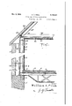
- FIG. 1 is a vertical cross sectional View of the construction embodying this invention showing the vertical angle iron supporting members and the manner in which the outer wall is supported and spaced thereby.
- Fig. 2 is a horizontal cross sectional view taken on lines 2--2 of Fig. l looking in the direction of the arrows of the wall embodying this invention, illustrating the manner in which the tie members are mounted between complementary angle iron l frame members and showing the details adherent thereto.
- Fig. 3 is a vertical cross sectional View through one of the angle iron frame members illustrating the interposed brous strip mounted between complementary flange portions of abutting angle irons.
- Fig. 4 is a detailed view showing the manner in which the tie member is attached to the fibrous strip interposed between the flanges of the complementary angle irons, and
- Fig. 5 is a detail cross sectional view of a modified form of anchoring means for the tie members.
- each of the joint rails i may be suitably braced by means of truss work for reinforcing purposes.
- 'I'he building in- 15 cludes a floor 9 formed of suitable material and supported by a layer of concrete I or the like.
- the vertical walls of the building ⁇ are formed of spaced inner and outer walls I I ,and I2, re- ⁇ 20 spectively, to provide an all" space ⁇ l3 therebetween, allowing free circulation of air throughout the entire structure.
- the outer wall I2 is formed of brick or brick veneer
- the inner wall I I formed of a metal framework 25 covered by plasterboard or other composition .
- a series of 'angle irons I4 are arranged in vertical relation and have their lower ends supported on the foundation 5. As shown in Figure 2, a pair of angle 30 irons I4 are placed together so that the flanges extend in opposite directions and are bolted together by fastening means I5 such as bolt nuts or rivets.
- tie members I6 are interposed between the angle irons I4 as shown in Fig. 2, 40 and may have their outer free ends embedded in the outer brick wall I2 in order to maintain the walls in spaced relation.
- Composition boards I'l and I8 are mounted on the inside and outside of the vertical frame mem- 45 bers I4 and may be fastened in place by lathing clips of the usual type, attached to the vertical angle supporting members.
- a layer of plaster is provided as at I9 for producing a nished appearance. 50
- Horizontal angle irons I4 Connected to the top portions of the Vertical angle irons I4 are horizontal beams 20, also formed of pairs of angle irons placed with abutting flanges fastened together.
- the horizontal beams 20 are connected to the vertical support- 55 ing beams I4 by bolts 2I which extend through bracket members 22 and are held in place by nuts 23.
- a ceiling 24 is attached to the horizontal angle beams 20 and may be finished with a coating of plaster 25.
- a roof 26 is mounted above the structure and includes angle irons 21, welded or otherwise secured to the horizontal angle irons 20 and arranged to extend over the inner and outer walls II andr I2 .to cover the air space I3.
- the walls of the entire buildings may be formed in identically the same manner as the vertically spaced walls II and I2, with minor alterations which may be produced by the average layman, and involves merely changes in the details of construction.
- the roof 26 may be formed of tile or cementitious material and that, if desired, the air space I3 may communicate with the space above the ceiling 24 and below the roof 26.
- Fig. 4 there is shown a modified form of connection between the outer and inner wall and 4as shown, the tie member 30 has its inner end bent angularly as at 3l for attachment by means f nails to the wooden or fibrous strip 32, mounted between the angle iron frame members I4 as shown in Figs. 1 to 3 inclusive.
- the free end of the tie member 3D may be embedded in the outer brick wall in the samefashion as is shown in Figs. 1 to 3.
- a further modified tie member is shown in Fig. 5, as at 30' and includes a strip of metal having one end bifurcated as at 3i to straddle the wooden strip 32 and be locked in place by the angle iron supporting members I4 on opposite sides thereof.
- the form of the invention herewith shown is to include Vwindow and door frames positioned at desired 1oangle iron frame members arranged with their abutting flanges placed face to face, a strip of wood interposed between the angle iron members, tie members having one of their ends connected to the outer wall andthe opposite end connected between the angle iron frame members and means for fastening the tie members in place between the angle iron frame members.
- a building of the character described cornprising an inner wall and an outer wall, said inner Wall being fabricated of a Wall board and angle iron construction, an outer wall spaced from the inner Wall formed of cementitious material, and means for spacing the inner wall from the outer wall including a series of spaced tie members having one end anchored in the outer wall and the opposite end connected between the angle iron frame members.
- a building of the character described comprising an inner wall and an outer wall spaced to form air circulating passages, said inner wall being formed of angle iron supporting framework including pairs of angle irons placed face to face, a fibrous strip interposed between the angle irons, means for fastening the angle irons and fibrous strips together and tie members for spacing the outer wall from the inner wall having one end embedded in the outer wall and the opposite end attached to the fibrous strip.
- a building wall comprising an inner wall and an outer wall providing an air Ventilating space, said inner wall being formed of vertically extending pairs of angle iron frame members arranged with their abutting flanges face to face, a strip of brous material interposed between the abutting flanges, composition boards placed.-y on opposite'sides of the vertical angle iron frame members and tie members for spacing the inner wall from the outer wall including metal straps having one end fastened between the abutting flanges of the angle irons and the opposite end.w
Landscapes
- Engineering & Computer Science (AREA)
- Architecture (AREA)
- Physics & Mathematics (AREA)
- Electromagnetism (AREA)
- Civil Engineering (AREA)
- Structural Engineering (AREA)
- Acoustics & Sound (AREA)
- Load-Bearing And Curtain Walls (AREA)
- Finishing Walls (AREA)
- Building Environments (AREA)
Description
Nr ww m Dec. 6, 1938. W A, pRlDE 2,139,461
HOLLOW WALL BUILDING CONSTRUCTION Filed sept. 16, 1957 2 slwe-slneet 1 William /LPr-ce Dec.v 6, 1938. w. A. PRIDE 2,139,461
HOLLOW WALL BUILDING CONSTRUCTION v 'ff/4 c:| E
/A f Y S. :1.4.
Patented Dec. 6, 1938 UNI-TED STATES PATENT OFFICE 2,139,461 E HOLLOW WALL BUILDING CONSTRUCTION William A. Pride, Medford, Mass. Application September 16, 1937, `Serial No. 164,091
Claims.
` This invention relates to improvements in hollow wall building constructions and more particularly to the type used for Ventilating purposes.
The primary object of this invention is to pro- 5 vide a building wall of the above mentioned character including a pair of spaced walls providing an air circulating space capable of being employed for heating and cooling as well as ventilating purposes.
`A further object of this invention is to provide a building wall of the above character, comprising a. series of frame angle irons having composition wall boards on opposite sides from which may be spaced an outer wall formed of brick or .115 brick veneer.
A still further object of this invention is to provide novel means for spacing the outer wall from the composition board covered framework, which includes spaced tie members connected to Y2l) the brick or brick veneer and to the angle iron supporting members, by nterposing the tie members` between pairs of angle irons forming the framework.
A still further object of this invention is to l25 provide a ventilated building wall of the character described, including angle iron supporting members placed together with a strip of wood or the like interposed therebetween for the purpose of receiving nails or other fastening means for the tie members.
` Other objects and advantages of the invention will become apparent during the course of the following detailed description forming a part of this specification and in which Fig. 1 is a vertical cross sectional View of the construction embodying this invention showing the vertical angle iron supporting members and the manner in which the outer wall is supported and spaced thereby.
Fig. 2 is a horizontal cross sectional view taken on lines 2--2 of Fig. l looking in the direction of the arrows of the wall embodying this invention, illustrating the manner in which the tie members are mounted between complementary angle iron l frame members and showing the details adherent thereto.
Fig. 3 is a vertical cross sectional View through one of the angle iron frame members illustrating the interposed brous strip mounted between complementary flange portions of abutting angle irons.
Fig. 4 is a detailed view showing the manner in which the tie member is attached to the fibrous strip interposed between the flanges of the complementary angle irons, and
( Cl. 'Y2-1) Fig. 5 is a detail cross sectional view of a modified form of anchoring means for the tie members.
In the drawings, wherein for the purpose of illustrating the invention in detail and-wherein 5 like reference characters will be employed to designate like parts throughout the same, the reference character 5 will generally be employed to designate the foundation of a building in accordance with this invention. 10
Mounted on the inner edge of the foundation 5 is an angle iron 6, adapted to form a support for the joint rails 'I as at 8. Each of the joint rails i may be suitably braced by means of truss work for reinforcing purposes. 'I'he building in- 15 cludes a floor 9 formed of suitable material and supported by a layer of concrete I or the like.
The vertical walls of the building `are formed of spaced inner and outer walls I I ,and I2, re-` 20 spectively, to provide an all" space`l3 therebetween, allowing free circulation of air throughout the entire structure. Preferably, the outer wall I2 is formed of brick or brick veneer, while the inner wall I I formed of a metal framework 25 covered by plasterboard or other composition .board In forming the inner walls, a series of 'angle irons I4 are arranged in vertical relation and have their lower ends supported on the foundation 5. As shown in Figure 2, a pair of angle 30 irons I4 are placed together so that the flanges extend in opposite directions and are bolted together by fastening means I5 such as bolt nuts or rivets. Interposed between the abutting faces of the angle irons I4 are strips of fibrous mate- 35 rial 32, and it has been found in practice that wood is preferable, although other similar materials may be used with equal advantages. At spaced intervals, tie members I6 are interposed between the angle irons I4 as shown in Fig. 2, 40 and may have their outer free ends embedded in the outer brick wall I2 in order to maintain the walls in spaced relation.
Composition boards I'l and I8 are mounted on the inside and outside of the vertical frame mem- 45 bers I4 and may be fastened in place by lathing clips of the usual type, attached to the vertical angle supporting members. On the inner composition board I'I, a layer of plaster is provided as at I9 for producing a nished appearance. 50
Connected to the top portions of the Vertical angle irons I4 are horizontal beams 20, also formed of pairs of angle irons placed with abutting flanges fastened together. The horizontal beams 20 are connected to the vertical support- 55 ing beams I4 by bolts 2I which extend through bracket members 22 and are held in place by nuts 23.
A ceiling 24 is attached to the horizontal angle beams 20 and may be finished with a coating of plaster 25. Also, a roof 26 is mounted above the structure and includes angle irons 21, welded or otherwise secured to the horizontal angle irons 20 and arranged to extend over the inner and outer walls II andr I2 .to cover the air space I3. The walls of the entire buildings may be formed in identically the same manner as the vertically spaced walls II and I2, with minor alterations which may be produced by the average layman, and involves merely changes in the details of construction.
It is to be understood that the roof 26 may be formed of tile or cementitious material and that, if desired, the air space I3 may communicate with the space above the ceiling 24 and below the roof 26.
In Fig. 4, there is shown a modified form of connection between the outer and inner wall and 4as shown, the tie member 30 has its inner end bent angularly as at 3l for attachment by means f nails to the wooden or fibrous strip 32, mounted between the angle iron frame members I4 as shown in Figs. 1 to 3 inclusive. The free end of the tie member 3D may be embedded in the outer brick wall in the samefashion as is shown in Figs. 1 to 3.
A further modified tie member is shown in Fig. 5, as at 30' and includes a strip of metal having one end bifurcated as at 3i to straddle the wooden strip 32 and be locked in place by the angle iron supporting members I4 on opposite sides thereof.
It is to be further understood that the form of the invention herewith shown is to include Vwindow and door frames positioned at desired 1oangle iron frame members arranged with their abutting flanges placed face to face, a strip of wood interposed between the angle iron members, tie members having one of their ends connected to the outer wall andthe opposite end connected between the angle iron frame members and means for fastening the tie members in place between the angle iron frame members.
2. A building of the character described cornprising an inner wall and an outer wall, said inner Wall being fabricated of a Wall board and angle iron construction, an outer wall spaced from the inner Wall formed of cementitious material, and means for spacing the inner wall from the outer wall including a series of spaced tie members having one end anchored in the outer wall and the opposite end connected between the angle iron frame members.
3. A building of the character described, comprising an inner wall and an outer wall spaced to form air circulating passages, said inner wall being formed of angle iron supporting framework including pairs of angle irons placed face to face, a fibrous strip interposed between the angle irons, means for fastening the angle irons and fibrous strips together and tie members for spacing the outer wall from the inner wall having one end embedded in the outer wall and the opposite end attached to the fibrous strip.
4. A building of the character described com-. prising an inner wall and an outer wall spaced therefrom, forming an air circulating passageway, said inner wall being formed of angle iron frame members, composite wall boards mounted on opposite sides of the angle iron frame memg bers and tie members, having one end embedded in the outer wall and the opposite end secured to the angle irons.
5. A building wall comprising an inner wall and an outer wall providing an air Ventilating space, said inner wall being formed of vertically extending pairs of angle iron frame members arranged with their abutting flanges face to face, a strip of brous material interposed between the abutting flanges, composition boards placed.-y on opposite'sides of the vertical angle iron frame members and tie members for spacing the inner wall from the outer wall including metal straps having one end fastened between the abutting flanges of the angle irons and the opposite end.w
embedded in the outer wall.
WILLIAM A. PRIDE.
Priority Applications (1)
| Application Number | Priority Date | Filing Date | Title |
|---|---|---|---|
| US164091A US2139461A (en) | 1937-09-16 | 1937-09-16 | Hollow wall building construction |
Applications Claiming Priority (1)
| Application Number | Priority Date | Filing Date | Title |
|---|---|---|---|
| US164091A US2139461A (en) | 1937-09-16 | 1937-09-16 | Hollow wall building construction |
Publications (1)
| Publication Number | Publication Date |
|---|---|
| US2139461A true US2139461A (en) | 1938-12-06 |
Family
ID=22592935
Family Applications (1)
| Application Number | Title | Priority Date | Filing Date |
|---|---|---|---|
| US164091A Expired - Lifetime US2139461A (en) | 1937-09-16 | 1937-09-16 | Hollow wall building construction |
Country Status (1)
| Country | Link |
|---|---|
| US (1) | US2139461A (en) |
Cited By (3)
| Publication number | Priority date | Publication date | Assignee | Title |
|---|---|---|---|---|
| US4663908A (en) * | 1983-09-08 | 1987-05-12 | Kestel Jr John F | Thermal efficient building |
| US4672787A (en) * | 1985-10-25 | 1987-06-16 | Murphy John J | Wall system construction, parts and methods of assembly |
| US4869037A (en) * | 1985-10-25 | 1989-09-26 | Murphy John J | Wall construction |
-
1937
- 1937-09-16 US US164091A patent/US2139461A/en not_active Expired - Lifetime
Cited By (3)
| Publication number | Priority date | Publication date | Assignee | Title |
|---|---|---|---|---|
| US4663908A (en) * | 1983-09-08 | 1987-05-12 | Kestel Jr John F | Thermal efficient building |
| US4672787A (en) * | 1985-10-25 | 1987-06-16 | Murphy John J | Wall system construction, parts and methods of assembly |
| US4869037A (en) * | 1985-10-25 | 1989-09-26 | Murphy John J | Wall construction |
Similar Documents
| Publication | Publication Date | Title |
|---|---|---|
| US2317634A (en) | Building construction | |
| US2191804A (en) | Building construction unit | |
| US1031926A (en) | Building construction. | |
| US1813909A (en) | Building construction | |
| US2724465A (en) | Panel and curtain wall construction | |
| GB1010812A (en) | Improvements in or relating to prefabricated buildings | |
| US2202783A (en) | Wall structure | |
| US2365145A (en) | Building construction | |
| US2138958A (en) | Prefabricated building construction | |
| US3339327A (en) | Assembly with prefabricated wall elements | |
| US2069755A (en) | Building construction | |
| US2864251A (en) | Building wall construction | |
| US2139461A (en) | Hollow wall building construction | |
| US3149437A (en) | Building construction | |
| US2372768A (en) | Building construction | |
| US1963410A (en) | Building unit | |
| US2042370A (en) | Metal support for wooden building construction | |
| US2575758A (en) | Framework for buildings | |
| US2476135A (en) | Furred concrete building wall | |
| US1988253A (en) | Metallic structure | |
| US2280832A (en) | Building | |
| US2307787A (en) | Building structure | |
| US2070479A (en) | Building panel | |
| GB1404675A (en) | Outer wall structure in a multi-storey building | |
| US1978473A (en) | Structural section |