US213936A - Improvement in burglar-alarms - Google Patents
Improvement in burglar-alarms Download PDFInfo
- Publication number
- US213936A US213936A US213936DA US213936A US 213936 A US213936 A US 213936A US 213936D A US213936D A US 213936DA US 213936 A US213936 A US 213936A
- Authority
- US
- United States
- Prior art keywords
- box
- slot
- burglar
- trigger
- alarms
- Prior art date
- Legal status (The legal status is an assumption and is not a legal conclusion. Google has not performed a legal analysis and makes no representation as to the accuracy of the status listed.)
- Expired - Lifetime
Links
- 238000010276 construction Methods 0.000 description 2
- 239000003550 marker Substances 0.000 description 2
- 239000002184 metal Substances 0.000 description 2
- 238000007599 discharging Methods 0.000 description 1
Images

Classifications
-
- A—HUMAN NECESSITIES
- A01—AGRICULTURE; FORESTRY; ANIMAL HUSBANDRY; HUNTING; TRAPPING; FISHING
- A01C—PLANTING; SOWING; FERTILISING
- A01C7/00—Sowing
- A01C7/008—Sod or grassland seeding
Definitions
- Patented A I879.
- My invention relates to a device for operating, adjusting, and discharging fire arms charged with ball or blank in burglar-alarms; and the novelty consists in the construction and arrangement of parts, as will be more fully hereinafter set forth, and pointed out in the claims.
- I employ a box of proper size and shape for the required purpose, said box having a removable top, secured by screws or otherwise.
- a frame or bridge in a slot or mortise in which is pivoted a lever, from the outer end of which are cords leading in opposite directions, and passing through apertures in the side of the box.
- the opposite extremity of this lever is wedgeshaped, so as to afford but little bearing-surface on the trigger-lever, against which it rests, and it is provided with a vertical standard or marker, which extends through a slot in the cover and indicates the condition of the trap.
- the trigger is pivoted in a slot or aperture in one side of the box, a portion thereof extending outside of the box, and adapted to operate upon the triggerof the fire-arm. It is provided with a slot, which receives the back end of the pivoted lever when iaa locked position, and has a metal covered surface, against which the same rests when the trap is set.
- the inner end of this trigger is held with a constant force against the pivoted lever by means of a spring, and a rod or rope is attached to the back side of the same near the end, and passes through the back-end of the box.
- the trap-surfacebf the trigger is situated between the slot and end, and thesame may be set by the diflerent cords without opening the box.
- a bearing-block for the arm having a vertical slot, is secured to the side of the box, and by means of a set-screw may be adjusted vertically at will.
- a similar block, forward is adjustable vertically, and may be also adjusted horizontally by means of a slot in that side of the box, so as to accommodate any length of arm. The arm rests in the upper jaws of these blocks, so that the trigger will rest within the finger-guard of the arm, forward of the trigger, as shown.
- Figure 1 is a representation of a plan view, the cover being broken away to show the in ternal mechanism; and Fig. 2 is a side eleva tion of an alarm embodying the improvements in my invention.
- A represents the box, and A the cover.
- a bridge, B having aperture 1), in which is pivoted, at'b, a lever, 0, from the forward end of which extend in opposite directions cords 0, which cords pass through the side of the box at 0
- the opposite end of this pivoted lever O is wedge-shaped at 0 and a marker,c ,extends upward and passes through a slot, a, in the cover A, as shown.
- D represents the trigger, pivoted at d in the side of the box, and provided with slot d, which receives the part 0 when in a locked condition.
- a metal covered surface, d affords but little friction when the trap is set, and a rope, E, &c., extends from the back through the rear end of the box at e.
- a spring, F holds the inner end of the trigger with a constant force against the end of the lever.
- Gr represents a set-block, having holdingjaws g for the pistol, &c., and a vertical slot, g, by means of which the same is vertically adjustable, a set-screw, a, holding it at any desired point.
- H represents a similar block, having jaws h and vertical slot h but the bolt in this latter case acts in a horizontal slot, I, in the side of the box, and the said block H is adjustable both horizontally and vertically, and may be held at any desired point'by the set-screw no.
Landscapes
- Life Sciences & Earth Sciences (AREA)
- Soil Sciences (AREA)
- Environmental Sciences (AREA)
- Fire Alarms (AREA)
Description
J. A. REESE. Burglar-Alarm.
No. 213,936. Patented A I879.
UNITED STATES PATENT OFFICE.
JOHN A. REESE, OF SEXEOA CITY, SOUTH CAROLINA:
IMPROVEMENT IN BURGLAR-ALARMS.
Specification forming part of Letters Patent No. 213,936, dated April 1, 1879; application filed February 1, 1879.
part of this specification.
My invention relates to a device for operating, adjusting, and discharging fire arms charged with ball or blank in burglar-alarms; and the novelty consists in the construction and arrangement of parts, as will be more fully hereinafter set forth, and pointed out in the claims.
In carrying out my invention I employ a box of proper size and shape for the required purpose, said box having a removable top, secured by screws or otherwise. Rigidly secured to the bottom of this box is a frame or bridge, in a slot or mortise in which is pivoted a lever, from the outer end of which are cords leading in opposite directions, and passing through apertures in the side of the box. The opposite extremity of this lever is wedgeshaped, so as to afford but little bearing-surface on the trigger-lever, against which it rests, and it is provided with a vertical standard or marker, which extends through a slot in the cover and indicates the condition of the trap.
The trigger is pivoted in a slot or aperture in one side of the box, a portion thereof extending outside of the box, and adapted to operate upon the triggerof the fire-arm. It is provided with a slot, which receives the back end of the pivoted lever when iaa locked position, and has a metal covered surface, against which the same rests when the trap is set. The inner end of this trigger is held with a constant force against the pivoted lever by means of a spring, and a rod or rope is attached to the back side of the same near the end, and passes through the back-end of the box. The trap-surfacebf the trigger is situated between the slot and end, and thesame may be set by the diflerent cords without opening the box.
A bearing-block for the arm, having a vertical slot, is secured to the side of the box, and by means of a set-screw may be adjusted vertically at will. A similar block, forward, is adjustable vertically, and may be also adjusted horizontally by means of a slot in that side of the box, so as to accommodate any length of arm. The arm rests in the upper jaws of these blocks, so that the trigger will rest within the finger-guard of the arm, forward of the trigger, as shown.
The operation of the invention is obvious, and the importance thereof lies chiefly in the simplicity of construction, efficiency, and certainty in action, and in its non-liability to get out of order.
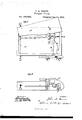
Figure 1 is a representation of a plan view, the cover being broken away to show the in ternal mechanism; and Fig. 2 is a side eleva tion of an alarm embodying the improvements in my invention.
Referring to the drawings, A represents the box, and A the cover. Secured to the bottom of the box A is a bridge, B, having aperture 1), in which is pivoted, at'b, a lever, 0, from the forward end of which extend in opposite directions cords 0, which cords pass through the side of the box at 0 The opposite end of this pivoted lever O is wedge-shaped at 0 and a marker,c ,extends upward and passes through a slot, a, in the cover A, as shown.
D represents the trigger, pivoted at d in the side of the box, and provided with slot d, which receives the part 0 when in a locked condition. A metal covered surface, d affords but little friction when the trap is set, and a rope, E, &c., extends from the back through the rear end of the box at e. A spring, F, holds the inner end of the trigger with a constant force against the end of the lever.
Gr represents a set-block, having holdingjaws g for the pistol, &c., and a vertical slot, g, by means of which the same is vertically adjustable, a set-screw, a, holding it at any desired point. H represents a similar block, having jaws h and vertical slot h but the bolt in this latter case acts in a horizontal slot, I, in the side of the box, and the said block H is adjustable both horizontally and vertically, and may be held at any desired point'by the set-screw no.
and slot 9, and the olock H, having jaws h and slot h, combined with the box A, having slot I, the trigger D, its operating mechanism, and the set-screws, as specified.
In testimony that I claim the foregoing as my own I atfix my signature in presenceof two witnesses.
JOHN ANDERSON REESE. Witnesses:
L. U. JORDAN, J. I". HAMMOND.
Publications (1)
| Publication Number | Publication Date |
|---|---|
| US213936A true US213936A (en) | 1879-04-01 |
Family
ID=2283340
Family Applications (1)
| Application Number | Title | Priority Date | Filing Date |
|---|---|---|---|
| US213936D Expired - Lifetime US213936A (en) | Improvement in burglar-alarms |
Country Status (1)
| Country | Link |
|---|---|
| US (1) | US213936A (en) |
Cited By (1)
| Publication number | Priority date | Publication date | Assignee | Title |
|---|---|---|---|---|
| USD349465S (en) | 1993-08-30 | 1994-08-09 | Steve Jacobs | Burglar alarm for doors |
-
0
- US US213936D patent/US213936A/en not_active Expired - Lifetime
Cited By (1)
| Publication number | Priority date | Publication date | Assignee | Title |
|---|---|---|---|---|
| USD349465S (en) | 1993-08-30 | 1994-08-09 | Steve Jacobs | Burglar alarm for doors |
Similar Documents
| Publication | Publication Date | Title |
|---|---|---|
| US213936A (en) | Improvement in burglar-alarms | |
| US221694A (en) | Improvement in spring-traps for throwing target-balls | |
| US111959A (en) | Improvement in burglar-alarms | |
| US393707A (en) | Simon a | |
| US212826A (en) | Improvement in toy pistols | |
| US116252A (en) | Improvement in gun-locks | |
| US562603A (en) | Halei to otis f | |
| US109035A (en) | Improvement in animal-traps | |
| US252230A (en) | George ligowsky | |
| US128565A (en) | Improvement in door-calls | |
| US212676A (en) | Improvement in door-bells | |
| US75248A (en) | Improvement in gun-looks | |
| US6514A (en) | Improved gun-lock | |
| US153924A (en) | Improvement in mounting and setting guns | |
| US83623A (en) | Improvement in bell-pull | |
| US179391A (en) | Improvement in burglar-alarms | |
| US121020A (en) | Improvement in fishing-reels | |
| US347343A (en) | Umbrella-support | |
| US566844A (en) | Automatic locking and unlocking device | |
| US232728A (en) | Ball-trap | |
| USRE6831E (en) | Improvement in gong attachments for engine-houses | |
| US13478A (en) | Alarm | |
| US323839A (en) | Safety-lock mechanism for fire-arms | |
| US358071A (en) | Fiekd | |
| US85848A (en) | Improvement in burglar-alarm |