US2139348A - Steam generator - Google Patents
Steam generator Download PDFInfo
- Publication number
- US2139348A US2139348A US197497A US19749738A US2139348A US 2139348 A US2139348 A US 2139348A US 197497 A US197497 A US 197497A US 19749738 A US19749738 A US 19749738A US 2139348 A US2139348 A US 2139348A
- Authority
- US
- United States
- Prior art keywords
- tubes
- section
- header
- steam
- fuel
- Prior art date
- Legal status (The legal status is an assumption and is not a legal conclusion. Google has not performed a legal analysis and makes no representation as to the accuracy of the status listed.)
- Expired - Lifetime
Links
- 239000000446 fuel Substances 0.000 description 58
- XLYOFNOQVPJJNP-UHFFFAOYSA-N water Substances O XLYOFNOQVPJJNP-UHFFFAOYSA-N 0.000 description 43
- 238000002485 combustion reaction Methods 0.000 description 30
- 239000000463 material Substances 0.000 description 6
- 239000000567 combustion gas Substances 0.000 description 4
- 239000003245 coal Substances 0.000 description 3
- 238000001816 cooling Methods 0.000 description 3
- 238000004326 stimulated echo acquisition mode for imaging Methods 0.000 description 3
- 238000013021 overheating Methods 0.000 description 2
- 239000011343 solid material Substances 0.000 description 2
- 241000290143 Pyrus x bretschneideri Species 0.000 description 1
- 229940000425 combination drug Drugs 0.000 description 1
- 238000000151 deposition Methods 0.000 description 1
- 239000007789 gas Substances 0.000 description 1
- 238000012986 modification Methods 0.000 description 1
- 230000004048 modification Effects 0.000 description 1
- 239000011819 refractory material Substances 0.000 description 1
- 238000007493 shaping process Methods 0.000 description 1
Images

Classifications
-
- F—MECHANICAL ENGINEERING; LIGHTING; HEATING; WEAPONS; BLASTING
- F22—STEAM GENERATION
- F22B—METHODS OF STEAM GENERATION; STEAM BOILERS
- F22B31/00—Modifications of boiler construction, or of tube systems, dependent on installation of combustion apparatus; Arrangements or dispositions of combustion apparatus
- F22B31/04—Heat supply by installation of two or more combustion apparatus, e.g. of separate combustion apparatus for the boiler and the superheater respectively
-
- Y—GENERAL TAGGING OF NEW TECHNOLOGICAL DEVELOPMENTS; GENERAL TAGGING OF CROSS-SECTIONAL TECHNOLOGIES SPANNING OVER SEVERAL SECTIONS OF THE IPC; TECHNICAL SUBJECTS COVERED BY FORMER USPC CROSS-REFERENCE ART COLLECTIONS [XRACs] AND DIGESTS
- Y10—TECHNICAL SUBJECTS COVERED BY FORMER USPC
- Y10S—TECHNICAL SUBJECTS COVERED BY FORMER USPC CROSS-REFERENCE ART COLLECTIONS [XRACs] AND DIGESTS
- Y10S122/00—Liquid heaters and vaporizers
- Y10S122/01—Air heater
Definitions
- 4It is one of the principal objects of the present invention to provide a steam generator having a wide range of capacity.
- E f v It is a further object of the present invention to provide alsteam generator suitable for coml0 bustion of the combustible constituentsof .pui-f l verized coal, oil, bark and other materials.
- Figure 1 is a vertical central sectional view taken from the front to the back of a preferred embodiment of the apparatus of the lpresent in-.
- Fig. 2 is a horizontal sectional view'taken ap'- proximately'on the line 2-2 of Fig. 1; and Fig. 3 isa Ifront elevational view of the apparatus shown in Fig-1. I.
- 0 ' having steam generating tubes in and along the wallsI I thereof, as hereinafter -more fully referred to, aboiler section
- the furnace section I0 preferably has a front wall I8, side walls I9, a bottom wall 20, a top wall 2
- the front wall I6 is provided near the top there- 'of and near the top of the furnace section I0 with an upper header 26 and near the bottom thereof with a ⁇ lower headerv 21, the headers 26' and 21 being'connected by a bank of tubes 28 also exposed to the radiant heat of combustion.
- the furnace section I0 is preferably divided centrally by a baffle or Wall- 30 which extends from thebottoln thereof to a location spaced from the top wall 2
- the baille or wall 30 terminates at the lower portion thereof at a lower. header 33.
- the floor 20 is preferably separated by bailies 34 and 35 into two sections, one of which is disposed below the upward pass 3
- the oor 20 is preferably lined with suitable refractory material in accordance with the characteristics of the fuel employed.
- .'Ihe floor 20 has located therein a pair of lower ⁇ headers 36 and 31 and banks of tubes 38 are provided for connecting the headers 36 and 31 with the headen 33.
- are provided in the oor 20 for the removal of ash or other non-combustible material depositing on the respective floor sections.
- Doors 42 may be provided for access to the interior of the furnace section I0.
- Another bank of tubes 43 is pro- 4vided for connecting the header 36 with the header 3T, a bank of tubes 44 is provided connecting the header 21 with the header 36, and additional tubes 45 are provided for connecting the lower headers 24 and 36.
- a lower header 46 is provided at the rear of the furnace section and is connected by a. bank of tubes 53 to the header 31.-
- of the furnace section is also provided with a header 41 and a bank of tubes 48 is provided preferably within the wall or baille 30 and connected to the lower header 33.
- This bank of tubes u has portions 4s bent outwarmy,
- portions 59 extending vertically and inclined portions 6I which are connected to the header 41.
- tubes 52 which extend from the lower header 33 to the header 41 in the top wall 2l, these tubes 52 being substantially straight tubes.
- the alternate disposition of the tubes 52 and the tubes 43 and the shaping of the tubes 48 in this manner detlects a substantial portion of ash and other non-combustible material therein back into the upward pass 3
- the boiler section II is provided, in communication with the furnace section I0.
- the boiler section II preferably has an upper steam-and-water drum 55 and vertically therebelow a lower water drum 56 and a baille 51 is provided for dividing the boiler section into an upward pass and a downward pass.
- the baille or wall 22 separates the furnace section I0 from the boiler section I I and extends forwardly from the steam-and-water drum 55 and downwardly and thus provides a rear wall for the furnace section I and the downward pass 32 thereof.
- An inclined rear wall 58 is also preferably provided to close the space between the lower header 46 and the water drum 56.
- a bank of tubes 60 is provided in the upward pass of the boiler section between the water drum 56 and the steam-and-water drum 55, with the forward line of tubes disposed close to the bave or wall 22 for preventing the overheating of the baiiie.
- a bank of tubes 6I is also provided in the downward pass of the boiler section between the water drum 56v and the steam-and-water drum 55.
- the banks of tubes 60 and 6I are preferably connected to the steam-and-water drum 55 below the water level thereof.
- a bank of tubes 63 is provided between the lower header 46 and the steam space of the steamand-water drum 55 and preferably includes inclined portions 64 extending upwardly along the inclined rear wall 56, and portions 65 inclined forwardly for deiiecting ash and other uncombustible material back towards the adjacent oor section for removal, and portions 66 extending upwardly along the baille or rear wall 22 to the steam-and-water drumy 55 for preventing the overheating of the baffle or rear wall 22.
- Banks of tubes 61 may also be provided adjacent the side walls I9 from the lower header 46 ⁇ to the steam space of the steam-and-water drum 55 with straight portions at the opening from the furnace section I 9 to the boiler section II.
- the upper headers 23 in the side walls I9A are connected to the steam spa'ce of the steam-andwater drum 55 by banks of tubes 68.
- Banks of tubes 69 which line the portion of the top wall 2l above the upward pass 3l are provided between the upper header 26 and the top header 41 and an additional bank of tubes 1l lining the portion of the top wall 2l above the downward pass 32 is provided between the header 41 and the steam space of the steam-and-waten drum 55.
- 'Ihe superheater section I2 comprises a bank of superheater tubes 12 which is connected to the steam space of the steam-and-water drum 55 and this bank preferably has the major portion of its length disposed within the upward pass of the boiler section II, and may have a portion thereof 'extending through the furnace section III.
- a superheater header 13 to which the bank of superheater tubes 12 is connected, is
- the economizer section I 3 is located to the rear of the boiler section II and in communication therewith, and includes a lower water drum 15 and an upper steam-and-water drum 16 substantially vertically disposed above the water drum 15.
- Walls 11 and 16 are preferably provided at the front and rear extremities of the economizer section I3 and a bave 19 centrally disposed within the economizer sectionl I3 is also provided and extends upwardly from the water drum 15 to a location spaced from the steam-and-water drum 16 to provide upward and downward passes for the combustion gases.
- are preferably provided respectively within the passes and extend from the water drum 15 to the steam-and-water drum 16.
- the steam-andwater drum 16 of the economizer section I3 is preferably connected to the steam-and-water drum 55 of the boiler section II by a bank of tubes 62 connecting the steam spaces of 'these drums 55 and 16, and another bank of tubes 83 is provided between the steam-and-water drum 16 of the economizer section I3 and the steamand-water drum 55 of the boiler section II below the water levels thereof.
- the air heater I4 for preheating the air for combustion is preferably provided to the rear of the economizer section I3 and in communication therewith so that the heat in the combustion gases ⁇ discharged from the economizer section I3 may be utilized for preheating the air for combustion.
- the air heater I4 has an inlet 84 for the combustion gases connected to the outlet of theeconomizer section, and an outlet 65 for the combustion gases, the outlet 85 being connected by a suitable duct 96 to the induced draft fan I5. fI'he outlet of the fan I5 is connected to the stack (not shown).
- the air heater I4 also has an air inlet 81 to which the forced draft fan I6 is connected by a suitable duct 88.
- the heated air outlet 89 of the air heater I4 is connected by a suitable duct 98 to the ducts 9I and 92, and a portion of this air may also be utilized with the fuel by means of the ducts 93.
- Suitable collecting chambers 95 and 96 may be provided in communication with the outlet of the boiler section I I and inlet of the economizer section I3 and with the outlet of the economizer section I3 and the hot gas inlet 84 of the air heater I4 for the cellecting and 'removal of ash or other non-combustible deposits which are carried over into these collecting chambers.
- Suitlable gates 91 are provided for access to these chambers 95 and 96 for such removal.
- each of the side walls I9 may be provided below the center thereof with suitable nozzles I 80 whichv are supplied by supply pipes I 6I for introducing pulverizedl coal, oil or other suitable fluent fuel.
- the top wall 2l of the furnace section I I above the downward pass 32 may also be provided with a plurality of fuel inlet nozzles
- fuel may be introducedonly at the nozzles Inland as a larger quantity of steam is required the nozzles
- 02 may be used in addition to supply fuel for combusextending upwardly at the'central part thereof and dividing said combustion chamber into an upward pass and a downward pass, fuel inletl devices for supplying fuel into said upward pass, and additional fuel inlet devices for supplying fuel into'said downward pass.
- a combustion chamber the walls of Isaid combustion chamber being lined with water tubes exposed to the radiant heat of the burning 'fuel in 'said chamber, said combustion chamber having' a verticalwall extending upwardly at the central part thereof and dividing said combustion chamber into an upward pass and a downward pass, steam generating tubes for cooling said Wall, fuel inlet devices for supplying fuel into said upward pass, and
- a combustion chamber In a steam generating unit, a combustion chamber, the walls of said combustion chamber being lined with water tubes exposedto the radiant heat of the burning fuel in said chamber, said combustion chamber having a vertical wall extending upwardly at the central part thereof and dividing said combustion chamber into an upward pass and a downward pass, fuel inlet devices in said side walls for supplying fuel into said upward pass, and additional fuel inlet devices insaid top wall for supplying fuel into said downward pass.
- a combustion chamber In a steam generating unit, a combustion chamber, the walls of said combustion chamber being lined with water tubes exposed to the radiant heat of the burningfuel in said chamber,
- said combustion chamber having a vertical wall extending upwardly at the central vpart thereof and dividing said combustion chamber intoan upward pass and a downward pass, steam generating tubes for cooling said wall, fuel inlet devices d)for supplying fuel into said combustion chamber,
- a steam generating unit the combination of a combustion chamber and a boiler section to the rear thereof, the Vwalls ofv said combustion chamber being lined with water tubes exposed to i the radiant heat of the burning fuel in said chamber, said boiler section including an upper steam-and-water drum and a lower water drum, banks of tubes in said boiler section connecting. said upper and lower drums, means for connecting the tubes in said combustion chamber to said upper drum, said combustion chamber having a vertical transverse wall extending upwardly at the central part thereof and dividing said combustlon chamber into an upward pass and' a downward pass, fuel inlet devices for supplying fuel into said upward pass, and additional ⁇ fuel inlet devices for supplying fuel .into said downward'pass; v
- a steam generating unit the combination ⁇ of a combustion chamber and a boiler section to the rear thereof, the wallsv of said combustion chamber being lined with water tubes exposed to the radiant heat of the burning fuel in said chamber, said boiler sectionincluding an .upper transverse steam-and-water drum and al lower transverse water drum substantially vertically-below said first mentioned drum, banks of tubes in-said boiler section connecting said upper and lower drums, means for connecting the tubes in said combustion chamber to said steam-and-water drum, ⁇ said combustion chamber having a vertical transverse wall extending upwardly at the central part thereof and dividing said combustion chamber into an upward pass and a downward pass, steam generating tubes for cooling said wall, means for connecting said tubes to said steam-and-water drum, fuel inlet devices in said side walls for supplying -fuel into said upward pass,4 fuel inlet ydevices in said top wall for supplying fuel downwardly into said downward pass, and air inlet devices in the lower portion of each of said passes.
- L 8 In a steam generatingvunit, ⁇ the combination of a furnace section and a boiler section, the vwalls of said furnace section being linedA with water tubes exposed to the radiant heat of the burning vfuelin said furnace section,l said furnace section having a transverse header centrally disposed in the lower part thereof and a transversfe header in the upper part thereof, a wall extending upwardly from said lower header to a point adjacent butspaced from said upper header for dividing said furnace section into an upward pass and a downward pass, a bank of tubes 'within' said wall extending fromsaid lower header to said upper header. and fuel inlet devices for delivering fuel into said furnace s ection. 4 f
- a steam generating unit the combination of a furnace section and a boiler section.
- the walls ofv said furnace section being lined with water tubes exposed to 4the radiant heat of the burning fuel in said furnace section, laid furnace section havingA a header disposed in the lower part thereof and a heade'rin the top thereof, a 'wall extending upwardly from said lower header to a point adjacent but spaced from said upper header for dividing said furnace section into an upward pass and a downward pass, a
- fuel inlet devices for delivering fuel' into said combustion chamber, a ydownwardly extending wall for separating said furnace section from said boiler section, and banks of tubes along each side ofn said wall, certain of said tubes having oiiset portions for deecting backwardly into said furnace section solid material tending to pass from said furnace sectionl to said boiler section.
- said furnace section having a transverse header centrally disposed in the lower part thereof and a transverse header in the top thereof, a wall extending upwardly from said lower header to a point adjacent but spaced from said upper header for dividing said furnace section' into an upward pass and a downward pass, a bank of tubes within said wall extending from said lower header to said upper header and having the upper portions thereof projecting into said upward pass.
- fuel inlet devices in the side wall for delivering fuel into said upward pass
- fuel inlet devicesjn the top of said furnace section and above said downward pass for delivering fuel downwardly into said downward pass
- a downwardly extending wall for separating said furnace section from -said boiler section.
- said furnace section having a transverse header ceny trally disposed in the lower part thereof and a transverse header in the top thereof, and a wall extending upwardly from said lower header to a point adjacent 4but spaced Afrom said upper header for dividing said furnace section into an upward pass and a downward pass, a bank of tubes within said wall extending from said lower header to said upper header and having the upper portions thereof projecting into said upward pass, fuel inlet devices in the side wall for delivering fuel into said upward pass, fuel inlet devices in the top of .said furnace section and J OHN PHILLIPS BADENHAUSEN.
Landscapes
- Engineering & Computer Science (AREA)
- Chemical & Material Sciences (AREA)
- Combustion & Propulsion (AREA)
- Physics & Mathematics (AREA)
- Thermal Sciences (AREA)
- Mechanical Engineering (AREA)
- General Engineering & Computer Science (AREA)
Description
Dec. 6, 1938. J. P. BADENHAUSEN STEAM GENERATOR Filed March 22, 1938v 2 Smets-sheet 1 l l IIII I 1 /flllnlll Dec. r6, 1938. J. BADENHAUSEN STEAM GENERATOR Filed March 22, 1938 2 Sheets-Sheet 2 Zenkawe Patented 6, 1938 PATENT OFFICE STEAM GENERATOR v .lohn Phillips nadenhausen, Philadelphia, Pa., usignor ofl one-half to Day and Zimmermann, Incorporated, Philadelphia, Pa., a corporation -or Maryland Application Mal-ch zz, 193s, serial No. 191,491 1a claim. 1 (c1. 122-336) This invention relates to steam generators andl more particularly to steam generators suitable for utilizing a plurality of combustible materials at 'a pluralityoflocations.
4It is one of the principal objects of the present invention to provide a steam generator having a wide range of capacity. E f v It is a further object of the present invention to provide alsteam generator suitable for coml0 bustion of the combustible constituentsof .pui-f l verized coal, oil, bark and other materials.
It is a. further .object of the present invention to provide a steam generator suitable for the com- I 4the annexed specification and claims. l
`The nature and characteristic features of the invention will be more readily understood from'l the following description, taken in connection with the accompanying drawings forlning part l hereof, in which:`
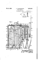
Figure 1 is a vertical central sectional view taken from the front to the back of a preferred embodiment of the apparatus of the lpresent in-.
`vention;
Fig. 2 is a horizontal sectional view'taken ap'- proximately'on the line 2-2 of Fig. 1; and Fig. 3 isa Ifront elevational view of the apparatus shown in Fig-1. I.
It will, of course, be understood that the description and drawings herein contained are il- I lustrative merely, and that'various modifications and changes may be made inthe structure disclosed without departing from the spirit'of the invention. v
Referring more particularly to the drawings, it
. will be seen that in the present steam generator there-is provided a. furnace section |0 'having steam generating tubes in and along the wallsI I thereof, as hereinafter -more fully referred to, aboiler section |I, a superheater section I2, an -economizer section I3, an air preheater I4, an induced draft fan I5 for the withdrawal of the products"ofcornbustiom.a forced draft fan- I6 for the supplying of air preheated by the preheater I4 to the furnace'section l0, and devices furnace section IU.
for introducing combustible material into the The furnace section I0 preferably has a front wall I8, side walls I9, a bottom wall 20, a top wall 2| and a rear wall 22, the exterior walls being suitably insulated.
Tile side walls I9 -are each provided near the top thereof withan upper header 23 and near 'the bottom thereof with a lower header 24, the headers 23 and 24 extending from the front wall I8 to the rear wall 22, and being connected by a' .bank .of tubes 25 lining the walls which is exposed to the radiant heat within the furnace section III.
The front wall I6 is provided near the top there- 'of and near the top of the furnace section I0 with an upper header 26 and near the bottom thereof with a`lower headerv 21, the headers 26' and 21 being'connected by a bank of tubes 28 also exposed to the radiant heat of combustion.
The furnace section I0 is preferably divided centrally by a baffle or Wall- 30 which extends from thebottoln thereof to a location spaced from the top wall 2| to provide within the furnace section vI0 an upward pass 3| and a downward pass 32. The baille or wall 30 terminates at the lower portion thereof at a lower. header 33.
The floor 20 is preferably separated by bailies 34 and 35 into two sections, one of which is disposed below the upward pass 3| and the other of which is disposed below the downward pass 32. -The oor 20 is preferably lined with suitable refractory material in accordance with the characteristics of the fuel employed.
.'Ihe floor 20 has located therein a pair of lower ^headers 36 and 31 and banks of tubes 38 are provided for connecting the headers 36 and 31 with the headen 33. Suitable gates 40 and 4| are provided in the oor 20 for the removal of ash or other non-combustible material depositing on the respective floor sections. Doors 42 may be provided for access to the interior of the furnace section I0. Another bank of tubes 43 is pro- 4vided for connecting the header 36 with the header 3T, a bank of tubes 44 is provided connecting the header 21 with the header 36, and additional tubes 45 are provided for connecting the lower headers 24 and 36. A lower header 46 is provided at the rear of the furnace section and is connected by a. bank of tubes 53 to the header 31.-
The top wall 2| of the furnace section is also provided with a header 41 and a bank of tubes 48 is provided preferably within the wall or baille 30 and connected to the lower header 33. This bank of tubes u has portions 4s bent outwarmy,
portions 59 extending vertically and inclined portions 6I which are connected to the header 41. Alternating with the tubes 48 are tubes 52 which extend from the lower header 33 to the header 41 in the top wall 2l, these tubes 52 being substantially straight tubes. The alternate disposition of the tubes 52 and the tubes 43 and the shaping of the tubes 48 in this manner detlects a substantial portion of ash and other non-combustible material therein back into the upward pass 3| for collection and withdrawal at the bottom thereof.
To the rear of the furnace section I8 the boiler section II is provided, in communication with the furnace section I0.
The boiler section II preferably has an upper steam-and-water drum 55 and vertically therebelow a lower water drum 56 and a baille 51 is provided for dividing the boiler section into an upward pass and a downward pass. The baille or wall 22 separates the furnace section I0 from the boiler section I I and extends forwardly from the steam-and-water drum 55 and downwardly and thus provides a rear wall for the furnace section I and the downward pass 32 thereof.
An inclined rear wall 58 is also preferably provided to close the space between the lower header 46 and the water drum 56.
A bank of tubes 60 is provided in the upward pass of the boiler section between the water drum 56 and the steam-and-water drum 55, with the forward line of tubes disposed close to the baiile or wall 22 for preventing the overheating of the baiiie. A bank of tubes 6I is also provided in the downward pass of the boiler section between the water drum 56v and the steam-and-water drum 55. The banks of tubes 60 and 6I are preferably connected to the steam-and-water drum 55 below the water level thereof.
A bank of tubes 63 is provided between the lower header 46 and the steam space of the steamand-water drum 55 and preferably includes inclined portions 64 extending upwardly along the inclined rear wall 56, and portions 65 inclined forwardly for deiiecting ash and other uncombustible material back towards the adjacent oor section for removal, and portions 66 extending upwardly along the baille or rear wall 22 to the steam-and-water drumy 55 for preventing the overheating of the baffle or rear wall 22.
Banks of tubes 61 may also be provided adjacent the side walls I9 from the lower header 46` to the steam space of the steam-and-water drum 55 with straight portions at the opening from the furnace section I 9 to the boiler section II.
The upper headers 23 in the side walls I9A are connected to the steam spa'ce of the steam-andwater drum 55 by banks of tubes 68. Banks of tubes 69 which line the portion of the top wall 2l above the upward pass 3l are provided between the upper header 26 and the top header 41 and an additional bank of tubes 1l lining the portion of the top wall 2l above the downward pass 32 is provided between the header 41 and the steam space of the steam-and-waten drum 55.
'Ihe superheater section I2 comprises a bank of superheater tubes 12 which is connected to the steam space of the steam-and-water drum 55 and this bank preferably has the major portion of its length disposed within the upward pass of the boiler section II, and may have a portion thereof 'extending through the furnace section III. A superheater header 13 to which the bank of superheater tubes 12 is connected, is
also provided for the withdrawal of the superheated steam.
The economizer section I 3 is located to the rear of the boiler section II and in communication therewith, and includes a lower water drum 15 and an upper steam-and-water drum 16 substantially vertically disposed above the water drum 15.
Walls 11 and 16 are preferably provided at the front and rear extremities of the economizer section I3 and a baiile 19 centrally disposed within the economizer sectionl I3 is also provided and extends upwardly from the water drum 15 to a location spaced from the steam-and-water drum 16 to provide upward and downward passes for the combustion gases. Banks of tubes 88 and 8| are preferably provided respectively within the passes and extend from the water drum 15 to the steam-and-water drum 16. The steam-andwater drum 16 of the economizer section I3 is preferably connected to the steam-and-water drum 55 of the boiler section II by a bank of tubes 62 connecting the steam spaces of 'these drums 55 and 16, and another bank of tubes 83 is provided between the steam-and-water drum 16 of the economizer section I3 and the steamand-water drum 55 of the boiler section II below the water levels thereof.
The air heater I4 for preheating the air for combustion is preferably provided to the rear of the economizer section I3 and in communication therewith so that the heat in the combustion gases `discharged from the economizer section I3 may be utilized for preheating the air for combustion. The air heater I4 has an inlet 84 for the combustion gases connected to the outlet of theeconomizer section, and an outlet 65 for the combustion gases, the outlet 85 being connected by a suitable duct 96 to the induced draft fan I5. fI'he outlet of the fan I5 is connected to the stack (not shown).
The air heater I4 also has an air inlet 81 to which the forced draft fan I6 is connected by a suitable duct 88. The heated air outlet 89 of the air heater I4 is connected by a suitable duct 98 to the ducts 9I and 92, and a portion of this air may also be utilized with the fuel by means of the ducts 93.
Fuel inlet devices -are providedand for this purpose each of the side walls I9 may be provided below the center thereof with suitable nozzles I 80 whichv are supplied by supply pipes I 6I for introducing pulverizedl coal, oil or other suitable fluent fuel.
The top wall 2l of the furnace section I I above the downward pass 32 may also be provided with a plurality of fuel inlet nozzles |62 which are supplied by supply pipes |83 for introducing pulverized coal, oil or othersuitable fuel downwardly into the top of the downward pass 32. It will, of course, be understood that air may be added with the fluent fuel in the well known manner, ducts 93 being provided for this purpose.
While in most instances the same kind of fluent fuel will be introduced at the fuel inlet nozzles `||i|i and at the fuel inlet nozzles |02 different kinds of fuel may, if desired, be introduced thereby. It
will be understood that, if desired, fuel may be introducedonly at the nozzles Inland as a larger quantity of steam is required the nozzles |02 may be used in addition to supply fuel for combusextending upwardly at the'central part thereof and dividing said combustion chamber into an upward pass and a downward pass, fuel inletl devices for supplying fuel into said upward pass, and additional fuel inlet devices for supplying fuel into'said downward pass.
2. In a steam generating unit, a combustion chamber, the walls of Isaid combustion chamber being lined with water tubes exposed to the radiant heat of the burning 'fuel in 'said chamber, said combustion chamber having' a verticalwall extending upwardly at the central part thereof and dividing said combustion chamber into an upward pass and a downward pass, steam generating tubes for cooling said Wall, fuel inlet devices for supplying fuel into said upward pass, and
additional fuel inlet devicesfor supplying fuel` into said downward pass.
3. In a steam generating unit, a combustion chamber, the walls of said combustion chamber being lined with water tubes exposedto the radiant heat of the burning fuel in said chamber, said combustion chamber having a vertical wall extending upwardly at the central part thereof and dividing said combustion chamber into an upward pass and a downward pass, fuel inlet devices in said side walls for supplying fuel into said upward pass, and additional fuel inlet devices insaid top wall for supplying fuel into said downward pass.
4. In a steam generating unit, a combustion chamber, the walls of said combustion chamber being lined with water tubes exposed to the radiant heat of the burningfuel in said chamber,
said combustion chamber having a vertical wall extending upwardly at the central vpart thereof and dividing said combustion chamber intoan upward pass and a downward pass, steam generating tubes for cooling said wall, fuel inlet devices d)for supplying fuel into said combustion chamber,
separate collecting spaces at the bottom of each o f said passes, and air inlet devices 'in the lower portions of each of said passes.
5. In a steam generating unit, the combination of a combustion chamber and a boiler section to the rear thereof, the Vwalls ofv said combustion chamber being lined with water tubes exposed to i the radiant heat of the burning fuel in said chamber, said boiler section including an upper steam-and-water drum and a lower water drum, banks of tubes in said boiler section connecting. said upper and lower drums, means for connecting the tubes in said combustion chamber to said upper drum, said combustion chamber having a vertical transverse wall extending upwardly at the central part thereof and dividing said combustlon chamber into an upward pass and' a downward pass, fuel inlet devices for supplying fuel into said upward pass, and additional` fuel inlet devices for supplying fuel .into said downward'pass; v
6. In a steam generating` unit, the combination of a combustion chamber and a boiler sec, tion to the rear thereof, the walls of said combustion chamber beinglined with water tubes exposed to the radiant heat of the burning fuel.
tubes to said steam-and-water drum, fuel inletl devices for supplying fuel into said combustion chamber, and air inlet devices in the lower portion of each of said passes.
7. In a steam generating unit, the combination \of a combustion chamber and a boiler section to the rear thereof, the wallsv of said combustion chamber being lined with water tubes exposed to the radiant heat of the burning fuel in said chamber, said boiler sectionincluding an .upper transverse steam-and-water drum and al lower transverse water drum substantially vertically-below said first mentioned drum, banks of tubes in-said boiler section connecting said upper and lower drums, means for connecting the tubes in said combustion chamber to said steam-and-water drum, `said combustion chamber having a vertical transverse wall extending upwardly at the central part thereof and dividing said combustion chamber into an upward pass and a downward pass, steam generating tubes for cooling said wall, means for connecting said tubes to said steam-and-water drum, fuel inlet devices in said side walls for supplying -fuel into said upward pass,4 fuel inlet ydevices in said top wall for supplying fuel downwardly into said downward pass, and air inlet devices in the lower portion of each of said passes.
L 8. In a steam generatingvunit, `the combination of a furnace section and a boiler section, the vwalls of said furnace section being linedA with water tubes exposed to the radiant heat of the burning vfuelin said furnace section,l said furnace section having a transverse header centrally disposed in the lower part thereof and a transversfe header in the upper part thereof, a wall extending upwardly from said lower header to a point adjacent butspaced from said upper header for dividing said furnace section into an upward pass and a downward pass, a bank of tubes 'within' said wall extending fromsaid lower header to said upper header. and fuel inlet devices for delivering fuel into said furnace s ection. 4 f
9. In a steam generating unit, the combination of a furnace section and a boiler section. the walls ofv said furnace section being lined with water tubes exposed to 4the radiant heat of the burning fuel in said furnace section, laid furnace section havingA a header disposed in the lower part thereof and a heade'rin the top thereof, a 'wall extending upwardly from said lower header to a point adjacent but spaced from said upper header for dividing said furnace section into an upward pass and a downward pass, a
bank of tubes within said wall extending from said lower header to said upper header, fuel inlet devices for delivering fuel into said furthe walls of said furnace section being lined with water tubes exposed to the radiant heat of the burning fuel in said furnace section, said furnace section having a transverse header entrally disposed in the lower part thereof and a transverse header in the top thereof, a wall extending upwardly from said lower header to a point adjacent-but spaced from said upper header for dividing said furnace section into an upward pass and a vdownward pass, a bank of tubes extending from said lower header to said upper header. and having the upper portions thereof projecting into said upward pass, fuel inlet devices for delivering fuel' into said combustion chamber, a ydownwardly extending wall for separating said furnace section from said boiler section, and banks of tubes along each side ofn said wall, certain of said tubes having oiiset portions for deecting backwardly into said furnace section solid material tending to pass from said furnace sectionl to said boiler section.
ll. In a steam generating unit, the combi-- nation of a furnace section and a boiler section,
the walls of said furnace section being lined with water tubes exposed to the radiant heat of the burning fuel in said furnace section, said furnace section having a transverse header centrally disposed in the lower part thereof and a transverse header in the top thereof, a wall extending upwardly from said lower header to a point adjacent but spaced from said upper header for dividing said furnace section' into an upward pass and a downward pass, a bank of tubes within said wall extending from said lower header to said upper header and having the upper portions thereof projecting into said upward pass. fuel inlet devices in the side wall for delivering fuel into said upward pass, fuel inlet devicesjn the top of said furnace section and above said downward pass for delivering fuel downwardly into said downward pass, a downwardly extending wall for separating said furnace section from -said boiler section. banks of tubes along each side of said wall. certain of said tubes having oifset portions for deflecting backwardly into said furnace section solid material tending to pass from said furnace section to said boiler section, and means for supplying air to said furnace section.
12. In a steam generating unit the combination of a furnace section and a boiler section,v
the walls of said furnace section being lined with water tubes exposed to the radiant heat of the burning fuel in said section, said furnace section having a transverse header ceny trally disposed in the lower part thereof and a transverse header in the top thereof, and a wall extending upwardly from said lower header to a point adjacent 4but spaced Afrom said upper header for dividing said furnace section into an upward pass and a downward pass, a bank of tubes within said wall extending from said lower header to said upper header and having the upper portions thereof projecting into said upward pass, fuel inlet devices in the side wall for delivering fuel into said upward pass, fuel inlet devices in the top of .said furnace section and J OHN PHILLIPS BADENHAUSEN.
Priority Applications (1)
| Application Number | Priority Date | Filing Date | Title |
|---|---|---|---|
| US197497A US2139348A (en) | 1938-03-22 | 1938-03-22 | Steam generator |
Applications Claiming Priority (1)
| Application Number | Priority Date | Filing Date | Title |
|---|---|---|---|
| US197497A US2139348A (en) | 1938-03-22 | 1938-03-22 | Steam generator |
Publications (1)
| Publication Number | Publication Date |
|---|---|
| US2139348A true US2139348A (en) | 1938-12-06 |
Family
ID=22729653
Family Applications (1)
| Application Number | Title | Priority Date | Filing Date |
|---|---|---|---|
| US197497A Expired - Lifetime US2139348A (en) | 1938-03-22 | 1938-03-22 | Steam generator |
Country Status (1)
| Country | Link |
|---|---|
| US (1) | US2139348A (en) |
Cited By (10)
| Publication number | Priority date | Publication date | Assignee | Title |
|---|---|---|---|---|
| US2512677A (en) * | 1946-01-04 | 1950-06-27 | Babcock & Wilcox Co | Steam generator |
| US2519566A (en) * | 1945-11-10 | 1950-08-22 | Comb Eng Superheater Inc | Superheater for chemical recovery units |
| US2551137A (en) * | 1945-03-03 | 1951-05-01 | Kennedy Van Saun Mfg & Eng | Steam generator unit |
| US2567837A (en) * | 1946-11-02 | 1951-09-11 | American Eng Co Ltd | Stoker furnace |
| US2581896A (en) * | 1949-04-26 | 1952-01-08 | Babcock & Wilcox Co | Vapor generator |
| US2620780A (en) * | 1949-08-10 | 1952-12-09 | Babcock & Wilcox Co | Waste heat vapor generator |
| US2673787A (en) * | 1946-01-18 | 1954-03-30 | John E Greenawalt | Method and apparatus for recovering chemical products from waste materials |
| US2816526A (en) * | 1953-04-20 | 1957-12-17 | Svenska Maskinverken Ab | Method of and apparatus for generating steam |
| US2979041A (en) * | 1957-02-07 | 1961-04-11 | Babcock & Wilcox Co | Vapor generator |
| DE976071C (en) * | 1952-10-14 | 1963-02-14 | Duerrwerke Ag | Forced once-through boiler with a large load range and a low-load combustion downstream from the main combustion |
-
1938
- 1938-03-22 US US197497A patent/US2139348A/en not_active Expired - Lifetime
Cited By (10)
| Publication number | Priority date | Publication date | Assignee | Title |
|---|---|---|---|---|
| US2551137A (en) * | 1945-03-03 | 1951-05-01 | Kennedy Van Saun Mfg & Eng | Steam generator unit |
| US2519566A (en) * | 1945-11-10 | 1950-08-22 | Comb Eng Superheater Inc | Superheater for chemical recovery units |
| US2512677A (en) * | 1946-01-04 | 1950-06-27 | Babcock & Wilcox Co | Steam generator |
| US2673787A (en) * | 1946-01-18 | 1954-03-30 | John E Greenawalt | Method and apparatus for recovering chemical products from waste materials |
| US2567837A (en) * | 1946-11-02 | 1951-09-11 | American Eng Co Ltd | Stoker furnace |
| US2581896A (en) * | 1949-04-26 | 1952-01-08 | Babcock & Wilcox Co | Vapor generator |
| US2620780A (en) * | 1949-08-10 | 1952-12-09 | Babcock & Wilcox Co | Waste heat vapor generator |
| DE976071C (en) * | 1952-10-14 | 1963-02-14 | Duerrwerke Ag | Forced once-through boiler with a large load range and a low-load combustion downstream from the main combustion |
| US2816526A (en) * | 1953-04-20 | 1957-12-17 | Svenska Maskinverken Ab | Method of and apparatus for generating steam |
| US2979041A (en) * | 1957-02-07 | 1961-04-11 | Babcock & Wilcox Co | Vapor generator |
Similar Documents
| Publication | Publication Date | Title |
|---|---|---|
| US2139348A (en) | Steam generator | |
| US2330240A (en) | Steam generator | |
| US2245209A (en) | Fluid heat exchange apparatus | |
| US2231872A (en) | Radiant boiler | |
| US1858450A (en) | Pulverized fuel combustion | |
| US2222530A (en) | Steam generator | |
| US2902982A (en) | Forced circulation vapor generating units | |
| US1930688A (en) | Boiler | |
| US2354059A (en) | Steam generator | |
| US1992953A (en) | Steam boiler | |
| US2228590A (en) | Steam generator | |
| US1815086A (en) | Steam generator | |
| US2366717A (en) | Apparatus for generating and superheating steam | |
| US1733474A (en) | Boiler furnace | |
| US2306097A (en) | Steam generator | |
| US2737160A (en) | Steam generators employing radiant superheaters and reheaters | |
| US3265039A (en) | Burning chamber cells formed by horizontal partition-forming tubes | |
| US2197387A (en) | Furnace | |
| US2902010A (en) | Radiant tubular heat exchanger | |
| US1864366A (en) | Boiler | |
| US2402993A (en) | Steam generator | |
| US2109278A (en) | Steam boiler | |
| US2107022A (en) | Steam generator | |
| US1830155A (en) | Art of generating steam | |
| US2243862A (en) | Steam generator |