US2128317A - Rotary sheet transfer mechanism - Google Patents
Rotary sheet transfer mechanism Download PDFInfo
- Publication number
- US2128317A US2128317A US123344A US12334437A US2128317A US 2128317 A US2128317 A US 2128317A US 123344 A US123344 A US 123344A US 12334437 A US12334437 A US 12334437A US 2128317 A US2128317 A US 2128317A
- Authority
- US
- United States
- Prior art keywords
- sheet
- transfer mechanism
- transfer
- rest
- printing
- Prior art date
- Legal status (The legal status is an assumption and is not a legal conclusion. Google has not performed a legal analysis and makes no representation as to the accuracy of the status listed.)
- Expired - Lifetime
Links
- 230000010355 oscillation Effects 0.000 description 3
- 230000000994 depressogenic effect Effects 0.000 description 2
- 101100379079 Emericella variicolor andA gene Proteins 0.000 description 1
- 241000282338 Mustela putorius Species 0.000 description 1
- 238000010276 construction Methods 0.000 description 1
- 230000000737 periodic effect Effects 0.000 description 1
- 230000000717 retained effect Effects 0.000 description 1
- 230000000979 retarding effect Effects 0.000 description 1
- 239000011435 rock Substances 0.000 description 1
Images


Classifications
-
- B—PERFORMING OPERATIONS; TRANSPORTING
- B41—PRINTING; LINING MACHINES; TYPEWRITERS; STAMPS
- B41F—PRINTING MACHINES OR PRESSES
- B41F21/00—Devices for conveying sheets through printing apparatus or machines
- B41F21/10—Combinations of transfer drums and grippers
-
- B—PERFORMING OPERATIONS; TRANSPORTING
- B41—PRINTING; LINING MACHINES; TYPEWRITERS; STAMPS
- B41F—PRINTING MACHINES OR PRESSES
- B41F21/00—Devices for conveying sheets through printing apparatus or machines
- B41F21/04—Grippers
- B41F21/05—In-feed grippers
Definitions
- the invention relates to sheet transfer mechanism and has reference more particularly to an improved rotary sheet transfermeans which will operate to transfer a sheet only when the sheet is properly delivered thereto and accurately registered throughout itsleading edge.
- the improvements of the invention have particular application to mechanism for feeding sheets as shown in Patent No. 1,991,003 granted 1 to Burt D. Stevens on February 12, 1935 wherein the sheetsto be printed are engaged after having been brought to register while at rest on to the speed of a moving printing member such x as an impression cylinder and transferred thereto so that at the time when a sheet is grasped by the sheet holding means of the printing member it I' will have attained the surface speed of said member.
- a moving printing member such x as an impression cylinder
- said transfer means in the event a sheet is not delivered to I", said transfer means the same will operate as I usual. This is very undesirable for a number of reasons and it is also undesirable for the printing couple to operate in the absence of a sheet. Also actuation of the transfer means as heretofore constructed would take place although a sheet may not be properly registered, or if a part only of the leading edge of the sheet were properly registered, which would happen occasionally notwithstanding the efficiency wlthrwhich the mechanism operated to slow down a moving sheet and j bring the same to rest for registering purposes.
- the present invention is an improvement in otary sheet transfer means and accordingly the mproved structure overcomes the above objecionable features. More particularly the invenion resides in the provision of clutch means which ill permit the transfer mechanism to remain at est unless a sheet is delivered thereto and is i roperly registered throughout its leading edge. l us rotary sheet transfer means of the type ascribed when equipped with the improvements f the invention will not operate unless certain ecessary conditions are fulfilled, that is, feeding f a sheet thereto followed by accurate registraa sheet support and are subsequently accelerated the sheets are delivered to the transfer means ing purposes and in a manner preventing jarringl Application February r1 1937, Serial No. 123,344
- a more specific object of the invention is to provide impression cylinder tripping means in combination with rotary transfer mechanism havl5 ing accelerating motion for transferring a sheet from a position of rest to a printing cylinder, followed by uniform motion, and iinallyza decelerating motion for slowing down the next sheet prior to bringing the same to rest for registering purposes.
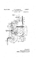
- Figure 1 is an elevational view showing the improvements of the invention applied t o rotary z sheet transfer means adapted to transfer sheets to a rotating impression cylinder;
- Figure 2 is a view similar to Figure 1 showing 3 the position the parts assume when the clutch of the invention has been tripped, preventing operation of the rotary transfer means; and Y Figure 3 is an elevational view'of the mechanism shown in Figure 1, the registering table 40 being shown in section to illustrate the means foi ⁇ detecting the presence or absence of a sheet.
- lil designates the impression cylinder and Il the blanket or plate' cylinder of the printing press chosen for illus- 45 trating the present invention.
- the blankettor plate cylinder Il is suitably journalled by means not shown, while the impression cylinder l0 is carried by shaft I3 journalled in the side frames of the press. yThese cylinders in the type of press shown are continuously rotating'and are geared together in the usual manner. Sheets are transferred from the registering table I4 to the impression cylinder Ill by the transfer mechanism designated in its entirety by l5, which feeds a r 65 Contact with the registering guides throughout its sheet to the usual grippers I6 carried by the cylinder.
- the sheet while being carried around the cylinder I0 will receive its impression as it passes between said cylinder and the plate cylinder II which will be inked in'any well known manner.
- Thetransfer mechanism I5 comprises arms I1 fixed to the transfer shaft ljournalled inframes I9 in the press and which carry sheet engaging grippers 20 pivotally mounted at 2I. Said grippers may be operated, in any well known manner to open and close. Arms I1 are joined'by'a member 22 carrying sheet retarding and aligning fingers 23 which extend into the path of the fed sheet and operate to slow down the sheet for registering purposes. Obviously, any desired number of grippers 20 and cooperating parts may be arranged on the transfer shaft I8, depending on the width of the sheets to be handled. In order to provide clearance for the grlppers 20 and sheet aligning fingers 23 the registering table is recessed so that a plurality of raised portions 25 are formed which will function to support the leading portion of the sheet on the table across its entire width.
- the improvements of the invention reside in the provision of sheet detecting means that will indicate the absence of a sheet on the registering table I4 at the. time the transfer mechanism is'at rest and which will further indicate an improperly registered sheet.
- the structure for accomplishing the above function consists of suction means which are incorporated in the registering table I4 at the forward edge thereof,l the same residing in a plurality of openings 24 in the upper surface of the raised portions 25 which connect with the suction tubl 28 leading to the disc valve 29.
- suction openings 24 are located in the registering table :along the entire width of the registering guides 26 associated with said table so that the same will detect not only the, absence of a sheet but also an improperly registered sheet, that is, one in which the leading edge is not in entire Width.
- suction tube 28 has connection with a disc valve 29, Figure 1, suitably fixed to cam shaft 30 carrying the cam 3I.
- the said disc valve in' turn connects with the main suction supply tube 32 and at the proper time in the operation of the press ,said valve will connect the supply tube 32 with tube 28 leading to the suction openings 24 in the registering table.
- tubev 33 leading to mem- Shaft.
- a coil spring 45 which yieldber 34 suitably fixed to one of the side frames I9 of the press.
- Said member is provided with a suction chamber having piston 35 to which is fixed av piston rod 36 projectingA above the member forming a projection 31.
- the coil spring 38 yieldingly forces said piston in a downward direction against the b ase of member 34.
- the transfershaft -I8 has suitably secured thereto a yoke member 40 having spaced arms 4I which slidably mount a trip latch 42 so as to permit reciprocation thereof.
- a yoke member 40 having spaced arms 4I which slidably mount a trip latch 42 so as to permit reciprocation thereof.
- 'I'he sides of said latch are recessed and the same is retained within said yoke, by screws 43 threaded in the arms 4I and which extend into said recesses.
- 'Ihe lower end of said trip latch is reduced in size forming a rod 44 which vextends into an opening provided therefor in the transfer Encircling said rod and having contact ingly forces said trip latch in an upward direction.
- the transfer mechanism is 'rotated by a driving disc 46, best shown in Figure 3, which is journaled by said transfer shaft I8 for rotation independently thereof.
- Said driving disc isI provided with an annular flange 41 partially shown in section in Figure 1 and which is provided with an opening through which the 4trip latch 42 is adapted to extend to thereby operatively connect the driving disc and the transfer shaft I8. causing rotation of the transfer shaft to take place in accordance with the driving impulses, transmitted thereto by the disc 46.
- Actuation of the trip latch 42 is controlled byA a trip pin adapted to engage the bifurcated upper end of said latch.
- Arm 5I of the bell crank lever 52 carries said trip pin 50the said lever being supported for pivotal movement by shaft 53 and having portion 54 formed on the lower end thereof. Said portion is provided with a shoulder adapted to contact projection 31, the saidbell crank lever being yieldingly biased in a direction to cause movement ofthe portion toward projection 31 by coil spring 55 fixed to the, bell crank lever at one endand secured-to the side frame of the press at its other end.
- the bell crank lever 52 may have movement under themaction o f spring 55 and cam 51, causing said lver to oscillate during which movement roller/56 will have contact with said cam 51.
- the projection 31 is normally located in the path oi' portion 54 integral with the lower end of said bell crank lever 52 and movement of the lever toward the right, Figure 1, is normally prevented by said projection.
- the transfer mechanism does not operate to transfer a sheet to the impression ,cylinder when said sheet 'has been improperly registered or accurately registered for only a portion of its leading ⁇ edge or when a sheet has not been fed thereto at all.
- the mechanism for tripping the printing couple receives its actuation from the bell crank lever 52.
- This mechanism consists of a lever Bil suitably journalled by the trip shaft El and carrying at its outer end roller S2 adapted to ride V'Within the cam race 63 formed in the cam disc 3
- the said lever 5@ is therefore given oscillating motion in timed relation with the operations of the press.
- an arm @d pivotally carrying at its outer end the dog t5 having an. arcuate shape and coincidn ing with the arcuate shape of recess to formed ln lever do.
- Pivotally secured to one end of dog at 5l is a rod 5E carrying at its upper end a pair of springs it.
- the coil spring 78 yieldingly holds the latch member 'll' against portion 80 formed integral with the bell crank lever 52. l
- cam'ft has rota1 .'tionvso as to connect the suction openings with the main suction supply tube 32 during the registering period of a sheet in contact with. the grsteringguidesd. To accomplish this regisn tering function of the sheet the transfer mechil event the sheet is. not properly registered.
- the transfer mechanism will also be held at rest if a sheet is not ferito the transfer mechanism at the proper time. .die though the registering guides 2'@ perform the front registralon of the sheet. the sheet retarciing and aligning ingers 23 also perform a registering function. It is entirety possible to omit the registering guides 2t and rely entirely on the fingers it for proper registration o ⁇ f the entire leading edge of the sheet. However, the main function ofv these fingers is to slow down the sheet, which takes place during the decelerating movement of the transfer mechanism and continues until the transfer mechanism is brought to rest. During .this period .of deceleration of the sheet the fingers function not only to slow down the sheet but also to register the leading edge ofthe same and thus in the mechanism disclosed the guides 26 perform a final registering function.
- the improvements of the invention will' have 5 operation to cause tripping of the clutch means and actuation of the trip shaft 6I only in the event a sheet is not fed to the transfer mechanism or if a sheet, ⁇ although fed thereto, is not accurately registered throughout its leading edge.
- the invention provides a manually actuated rod 82 having a handle or knob B3 and which is yieldingly biased outwardly by spring 84. Therefore normally the end of the rod opposite the knob is out of engagement with portion 5l.
- Said portion is formed with an opening l5 adapted to receive the end of the rod when the same is depressed by the operator and as long locked in an inoperative position, in which position the trip latch will be operatively located to cause successive rotations of the transfer mechamsm-to take place.
- rotary sheet transfer mechanism adapted to have movement from a position of rest for transferring a sheet to a printing member, means for registering a sheet while said transfer mechanism is at rest and before said sheet is transferred thereby.
- clutch means interposed between said transfer mechanism and the drivingmeans therefor, and means having operation to actuate said clutch means permitting said transfer mechanism to remain at rest in the event a sheet is not fed to said mechanism and l accurately registered by said registeringv means throughout its leading edge.
- rotary sheet transfer mechanism for feeding sheets to a member performing an operation thereon, driving means for said transfer mechanism having accelerating mo- .tion from a position ofrest whereby similar motion may "be imparted to said transfer mechanism so that at the time of transfer of said sheet the mechanism will 4have attained the surface speed of said member, clutch Vmeans interposed between the transfer mechanism and'drivingv means therefor, and means having operation in 3,'In a printing press, rotary sheet transfer mechanism for feeding sheets to a member per-- forming an operation thereon, driving means'for said transfer mechanism having acceleratingzmotion from a position of rest whereby similar motion may be imparted to said transfer mechanism so that at the time of transfer of said sheet the mechanism will have attained the surface speed of said member, registering guides for registering said sheet during the period of rest, clutch means interposed between saidtrans'fer mechanism and the driving means therefor. and means having operation in the event a sheet is not fedto said transfer mechanism and accurately registered 70 throughout its leading edge to actuate said clutch L
- a printing/couple of transfer mechanism adapted to have movement from a position of ⁇ rest for transferring a sheet to said printing couple, driving means for said mechanism having continuousr ⁇ operation, clutch means interposed between the transfer mechanism and said driving means, and means for tripping said clutch means and substantially simultaneously tripping the printing couple, said means having operation only in the event a sheet is not ⁇ fed to said transfer mechanism and properly registered during the period f of rest thereof, whereby said transfer mechanism is held at rest and said printing couple is tripped to prevent a printing operation.
- the combination-with a printing couple, of transfer mechanism adapted to have movement from a position of rest for transferring a sheet to said printing couple, driving means for said mechanism having continuous operation, registering guides ⁇ for registering the leading edge of said sheet during said period of Crest and before transfer of the sheet, clutch means interposed between the transfer mechanism and said driving means, 'and'J means for tripping said clutch means and substantially simultaneously tripping the printing couple, said means having operation only in the event a sheet is not fed to said transfer mechanism and properly registered by said registering guides, whereby said transfer mechanism is held at rest and said printing couple is tripped to prevent a printing operation.
- a printing couple for feeding sheets to said couple, driving means imparting periodic movement to said transfer mechanism from a position of rest, a clutch interposed between said sheet detecting means controlling the operation of said clutch and indirectly.
- controlling means for tripping said printingcouple to prevent a printing operation said sheet detecting meansN permitting tripping of the clutch and said printing couple only in the event a sheet is lnot y fed to saidv mechanism and properly registered s duringvtheperiod of rest.
- a printing couple for feeding sheets tol said couple, driving means therefor, said means coming to rest during each revolution, whereby a sheet may be registered during the period of rest of thectransfer mechanism vand prior tov being75 ,il
- sheet detecting means for detecting the presence or absence of a sheet at the transfer mechanism' during the registering period, and means controlled by the operation of said sheet detecting means for actuating said clutch.
- a printing couple for feeding sheets to said couple, driving means therefor, said means coming torest during each revolution whereby said transfer mechanism has a priod of rest for registering a sheet before transferring the same, a clutch interposed between saidl driving means and transfer mechanism, sheet detecting means for detecting the absence of a sheet or the presence of an improperly registered sheet at said transfer mechanism during the registering period, and means having operation to trip said clutchand also said printing couple, said sheet detecting means means preventing operation of y the clutch and printing couple tripping means provided a sheet has been fed to the transfer mechanism and properly registered during said period of rest.
- a printing couple of transfer mechanism including sheet retaining fingers adapted to have movement from a position of rest for transferring a sheet to said printing couple, driving means for Vsaidmechanism having continuous operation, a
- rotary sheet transfer mechanism for feeding sheets to a member performing an operation thereon
- driving means for said transfer mechanism having accelerating motion from a position of rest whereby similar motion may be imparted to said transfer mechanism so that at the time of transfer of said sheet the mechanism will have attained the surface speed of said member
- registering guides for registering the sheet during the period of rest and prior to transfer of the same andA clutch means responsive to the presence or absence of a sheet at said guides during their period of rest for controlling the operation of said transfer mechanism.
- a printing press the combination with a printing couple, of transfer mechanism adapted to have movement from a position of rest for transferring a sheet to said printing couple, driving means for said mechanism havingI continuous operation, a clutch interposed between the transfer mechanism and said driving means, sheet detector means having operation to trip said clutch in the event a sheet is not fed to said transfer mechanism and properly registered during the period of rest thereof, and means also controlled by said sheet detector means for tripping the printing couple, which operation takes place substantially simultaneously with the tripping of the clutch.
- a printing press the combination with a printing couple, of transfer mechanism adapted to have movement from a position of rest for transferring a sheet to said printing couple, driving means for said mechanism having continuous operation, a clutch located between the transfer mechanism and the said driving means, Vmeans for tripping said clutch, sheet detector means having operation to actuate the said tripping means for the clutch in the event a sheet is not fed to said transfer mechanism and properly registered during the period of rest thereof, and
Landscapes
- Supply, Installation And Extraction Of Printed Sheets Or Plates (AREA)
Description
Aug.30,1938. H, EPEYREBRUE f '2,128,311
OTRY SHEET TRANSFER MECHANISM I v FiledlFeb; 1, `195'? s sheets-shed V14 .Aug. 30, 1938. v H. E. PEYREBRUNE 2,128,317
ROTARY SHEETl TRANSFER MECHANISM Filed Feb. 1, 1937 :s sheets-sheet 2 Aug. 30, 1938. a H.. E. PEYREBRUNE 2,128,317
' ROTARY SHEET TRANSFER'MECHANISM FiledF'eb. 1; 1937 h 3 sheets-Sheet s atented Aug. 30,. 1938 untreu STATES PATENT oFFicE Ro'rARY SHEET TRANSFER MEcnAmsM of Illinois The invention relates to sheet transfer mechanism and has reference more particularly to an improved rotary sheet transfermeans which will operate to transfer a sheet only when the sheet is properly delivered thereto and accurately registered throughout itsleading edge.
The improvements of the invention have particular application to mechanism for feeding sheets as shown in Patent No. 1,991,003 granted 1 to Burt D. Stevens on February 12, 1935 wherein the sheetsto be printed are engaged after having been brought to register while at rest on to the speed of a moving printing member such x as an impression cylinder and transferred thereto so that at the time when a sheet is grasped by the sheet holding means of the printing member it I' will have attained the surface speed of said member. To make possible the registration of a sheet while at rest the transfer means of said patent is decelerated prior to being brought to rest and 'l while the same is deceierating. More particul larly, said sheets .are delivered to the transfer means when the velocity of said means is approximately the same as that of the sheet so that the sheets are gradually brought to rest for registerof the sheet. i However, in the event a sheet is not delivered to I", said transfer means the same will operate as I usual. This is very undesirable for a number of reasons and it is also undesirable for the printing couple to operate in the absence of a sheet. Also actuation of the transfer means as heretofore constructed would take place although a sheet may not be properly registered, or if a part only of the leading edge of the sheet were properly registered, which would happen occasionally notwithstanding the efficiency wlthrwhich the mechanism operated to slow down a moving sheet and j bring the same to rest for registering purposes.
The present invention is an improvement in otary sheet transfer means and accordingly the mproved structure overcomes the above objecionable features. More particularly the invenion resides in the provision of clutch means which ill permit the transfer mechanism to remain at est unless a sheet is delivered thereto and is i roperly registered throughout its leading edge. l us rotary sheet transfer means of the type ascribed when equipped with the improvements f the invention will not operate unless certain ecessary conditions are fulfilled, that is, feeding f a sheet thereto followed by accurate registraa sheet support and are subsequently accelerated the sheets are delivered to the transfer means ing purposes and in a manner preventing jarringl Application February r1 1937, Serial No. 123,344
14 Claims. (GLEN- 56) tion of the entire leading edge of the. same. The improvements of the present invention further reside in the provision of tripping means for the printing couple which Will have automatic operation in the event the transfer means remains at 5 rest to trip either the plate or impression cylinder, thereby preventing a printing operation. As a result., the present invention will insure delivery of all sheets in timed relation with other operating parts of the press and will insure perfect reg`- istration of each and every sheet printed by the printing couple associated therewith.
A more specific object of the invention is to provide impression cylinder tripping means in combination with rotary transfer mechanism havl5 ing accelerating motion for transferring a sheet from a position of rest to a printing cylinder, followed by uniform motion, and iinallyza decelerating motion for slowing down the next sheet prior to bringing the same to rest for registering purposes.
With these and various other objects in View, the invention may consist of certain novel features of construction and operation, as will be more fully described and particularly pointed out in the specification, drawings and claims appended hereto. A 'g In the drawings which illustrate anembodiment of the invention and wherein like reference characters are used to designate like parts- Figure 1 is an elevational view showing the improvements of the invention applied t o rotary z sheet transfer means adapted to transfer sheets to a rotating impression cylinder;
Figure 2 is a view similar to Figure 1 showing 3 the position the parts assume when the clutch of the invention has been tripped, preventing operation of the rotary transfer means; and Y Figure 3 is an elevational view'of the mechanism shown in Figure 1, the registering table 40 being shown in section to illustrate the means foi` detecting the presence or absence of a sheet.
Referring to the drawings, lil designates the impression cylinder and Il the blanket or plate' cylinder of the printing press chosen for illus- 45 trating the present invention. The blankettor plate cylinder Il is suitably journalled by means not shown, while the impression cylinder l0 is carried by shaft I3 journalled in the side frames of the press. yThese cylinders in the type of press shown are continuously rotating'and are geared together in the usual manner. Sheets are transferred from the registering table I4 to the impression cylinder Ill by the transfer mechanism designated in its entirety by l5, which feeds a r 65 Contact with the registering guides throughout its sheet to the usual grippers I6 carried by the cylinder. The sheet while being carried around the cylinder I0 will receive its impression as it passes between said cylinder and the plate cylinder II which will be inked in'any well known manner. l l i Thetransfer mechanism I5 comprises arms I1 fixed to the transfer shaft ljournalled inframes I9 in the press and which carry sheet engaging grippers 20 pivotally mounted at 2I. Said grippers may be operated, in any well known manner to open and close. Arms I1 are joined'by'a member 22 carrying sheet retarding and aligning fingers 23 which extend into the path of the fed sheet and operate to slow down the sheet for registering purposes. Obviously, any desired number of grippers 20 and cooperating parts may be arranged on the transfer shaft I8, depending on the width of the sheets to be handled. In order to provide clearance for the grlppers 20 and sheet aligning fingers 23 the registering table is recessed so that a plurality of raised portions 25 are formed which will function to support the leading portion of the sheet on the table across its entire width.
'Ihe transfer mechanism above described has rotation from a position of rest, as shown in Fig-v ure l, during which the 'sheet is registered by the guides 26 provided adjacent the front edge of the registering table I4 and which have pivotal movement on axis 21 so that the guides may movev forward' out lof the pathy of the sheet after their registering function is completed. The registered sheet is engaged by the grippers 2Iland accelerated motion is imparted to the transfer mechanism y so that when the sheet is presented tothe cylinder grippers it will have reached the surface speed of said cylinder. The transfer mechanism will continue to rotate uniformly for part of a revolution and will thenl have decelerating motion for the purpose of slowing down a'sheet and bringing the same to rest gradually for registering purposes. Fora more complete description of the transfer mechanism, its manner of operatiomand the driving means therefor, reference is made to v the StevensPatent No. 1,991,0(13 previously mentioned.
-The improvements of the invention reside in the provision of sheet detecting means that will indicate the absence of a sheet on the registering table I4 at the. time the transfer mechanism is'at rest and which will further indicate an improperly registered sheet. The structure for accomplishing the above function consists of suction means which are incorporated in the registering table I4 at the forward edge thereof,l the same residing in a plurality of openings 24 in the upper surface of the raised portions 25 which connect with the suction tubl 28 leading to the disc valve 29. The suction openings 24 are located in the registering table :along the entire width of the registering guides 26 associated with said table so that the same will detect not only the, absence of a sheet but also an improperly registered sheet, that is, one in which the leading edge is not in entire Width. I'he suction tube 28 has connection with a disc valve 29, Figure 1, suitably fixed to cam shaft 30 carrying the cam 3I. The said disc valve in' turn connects with the main suction supply tube 32 and at the proper time in the operation of the press ,said valve will connect the supply tube 32 with tube 28 leading to the suction openings 24 in the registering table. Also connecting with tube 28 is tubev 33 leading to mem- Shaft. at one end with the trip .latch and at its other' end with the shaft is a coil spring 45 which yieldber 34 suitably fixed to one of the side frames I9 of the press. Said member is provided with a suction chamber having piston 35 to which is fixed av piston rod 36 projectingA above the member forming a projection 31. The coil spring 38 yieldingly forces said piston in a downward direction against the b ase of member 34. f
The operation of the detecting means above described will occur in synchronism with the operations of the printing press since the cam shaft 30.
carrying disc valve 29, is suitably geared so as to rotate continuously and in timed relation with the impression cylinder. When a sheet is regis- Advantage is taken of the presence or absence of y said projection 31 tov control the actuationlof clutch mean's applied to the transfer mechanism, i
which structure will now be described.
' As shown in Figure 1, the transfershaft -I8 has suitably secured thereto a yoke member 40 having spaced arms 4I which slidably mount a trip latch 42 so as to permit reciprocation thereof. 'I'he sides of said latch are recessed and the same is retained within said yoke, by screws 43 threaded in the arms 4I and which extend into said recesses. 'Ihe lower end of said trip latch is reduced in size forming a rod 44 which vextends into an opening provided therefor in the transfer Encircling said rod and having contact ingly forces said trip latch in an upward direction.
The transfer mechanism is 'rotated by a driving disc 46, best shown in Figure 3, which is journaled by said transfer shaft I8 for rotation independently thereof. Said driving disc isI provided with an annular flange 41 partially shown in section in Figure 1 and which is provided with an opening through which the 4trip latch 42 is adapted to extend to thereby operatively connect the driving disc and the transfer shaft I8. causing rotation of the transfer shaft to take place in accordance with the driving impulses, transmitted thereto by the disc 46.
Actuation of the trip latch 42 is controlled byA a trip pin adapted to engage the bifurcated upper end of said latch. Arm 5I of the bell crank lever 52 carries said trip pin 50the said lever being supported for pivotal movement by shaft 53 and having portion 54 formed on the lower end thereof. Said portion is provided with a shoulder adapted to contact projection 31, the saidbell crank lever being yieldingly biased in a direction to cause movement ofthe portion toward projection 31 by coil spring 55 fixed to the, bell crank lever at one endand secured-to the side frame of the press at its other end. The
lowerend of said bell crank lever carries aroller 56which is adapted to have engagement with the cam 51 fixed to and rotating with shaft I3 carrying the impression cylinder.
In operation of the structure above described it will'be understood that the bell crank lever 52 may have movement under themaction o f spring 55 and cam 51, causing said lver to oscillate during which movement roller/56 will have contact with said cam 51. However, the projection 31 is normally located in the path oi' portion 54 integral with the lower end of said bell crank lever 52 and movement of the lever toward the right, Figure 1, is normally prevented by said projection. It will be clear from the previous description that said projection 37 will be located in the path of portion 54 when a sheet has been properly fed--to-the transfer mechanism and'regis-A tered throughout its leading edge since under these circumstances air will be prevented from entering the suction openings 2d andiipiston 35 in the member 34' will be caused to assume an elevated position against the tension of spring 35. However, in the event a sheet is not fed to said registering mechanism, or, if the sheet fed thereto is not properly registered throughout its leading edge, air will enter those openings remaining uncovered and under these circumstancesikair will not be extracted from the chamber in member 3S and thus piston 35 will remain in its loWermost position, locating projection 3F within the member., i
When the projection 3l' is not caused-to be located in the path of the bell crank lever 52 said lever will have movement toward the right under the tension of spring and which movement will be in timed relation with the rotation of the impression cylinder by reason of the cam 5l. Oscillation of the bell crank lever in this direction will cause the trip pin Eil to depress the trip latch tf, whereupon the .driving disc di and the transfer mechanism will be disconnected and rotation of the transfer gripper elements for transferring a sheet to the impression cylinder will not take place but said transfer mechanism will remain at rest.. Ilt is therefore seen that by reason of the improvements of the invention the transfer mechanism does not operate to transfer a sheet to the impression ,cylinder when said sheet 'has been improperly registered or accurately registered for only a portion of its leading` edge or when a sheet has not been fed thereto at all.
The mechanism for tripping the printing couple receives its actuation from the bell crank lever 52. .This mechanism consists of a lever Bil suitably journalled by the trip shaft El and carrying at its outer end roller S2 adapted to ride V'Within the cam race 63 formed in the cam disc 3 The said lever 5@ is therefore given oscillating motion in timed relation with the operations of the press. Suitably fixed to the trip shaft al is an arm @d pivotally carrying at its outer end the dog t5 having an. arcuate shape and coincidn ing with the arcuate shape of recess to formed ln lever do. Pivotally secured to one end of dog at 5l is a rod 5E carrying at its upper end a pair of springs it. Adapted to have slidable movement on rod t8 and positioned between springs 'Iltis a member "il having securement to arm lil of bell crank lever 'it suitably mounted for pivotal movement by shaft lt. The .bell crank lever '13 is yieldingly forced by spring l5 Iin a direction to cause arm l2 to move upwardly and its oppositely directed arm 16 to move downwardly. The shaft 53 journals the latch member 1i against which arm 'i6 is 'adapted to rest when the parts are in the position shown in Figure i.
The coil spring 78 yieldingly holds the latch member 'll' against portion 80 formed integral with the bell crank lever 52. l
In the operation `of the mechanism for tripping the impression cylinder lo or the plate cylinder It, as the case may be, it will he recalled that the projection 31 is normally located in the path of the bell crank lever 52 and therefore the oscillating movement of said levelI is normally re strlcted. However, vwhen a sheet is not fed to the .transfer mechanism, or, in the event a sheet is improperly registered, said projection will not extend in the path of portion 54 and the bell crank lever will have movement in a direction Vtoward the right under the action of spring 55.
-lever 6d. In other words, the said dog is oppositely positioned from that normally assumed by the same, as will be clear by comparing Figures il and 2. As lever @t is caused to oscillate in upward direction by rotation of the cam disc di movement will beimparted to dog @E vand to lever @It fixed to the trip shaft 6i with the result that rocking of said trip shaft will take piace and through connections from said shaft printing couple 'will he tripped to prevent a printe ing operation.
Mechanism having connection with the shaft Si andwhich is actuated upon oscillation of said shaft, as Aabove described, to cause tripping of either the impression cylinder or the plate cylin-n der is not disclosed as this structure forms no part of the present invention ano. any eoiwciiQ tional mechanisinv old and well known in. the art may be employed.
It will be understood that the cam'ft has rota1 .'tionvso as to connect the suction openings with the main suction supply tube 32 during the registering period of a sheet in contact with. the reglsteringguidesd. To accomplish this regisn tering function of the sheet the transfer mechil event the sheet is. not properly registered.
therefore follows that the transfer mechanism will also be held at rest if a sheet is not ferito the transfer mechanism at the proper time. .die though the registering guides 2'@ perform the front registralon of the sheet. the sheet retarciing and aligning ingers 23 also perform a registering function. It is entirety possible to omit the registering guides 2t and rely entirely on the fingers it for proper registration o`f the entire leading edge of the sheet. However, the main function ofv these fingers is to slow down the sheet, which takes place during the decelerating movement of the transfer mechanism and continues until the transfer mechanism is brought to rest. During .this period .of deceleration of the sheet the fingers function not only to slow down the sheet but also to register the leading edge ofthe same and thus in the mechanism disclosed the guides 26 perform a final registering function.
FIn the operation of a ,printing press equipped the projection 3l will be extended into the path 75 y of portion 54 to prevent oscillation of the lever 52 and actuation of the clutch means and tripping mechanism. f
The improvements of the invention will' have 5 operation to cause tripping of the clutch means and actuation of the trip shaft 6I only in the event a sheet is not fed to the transfer mechanism or if a sheet,` although fed thereto, is not accurately registered throughout its leading edge. In order to lock the lever 52 in position, as shown in Figure 1, to permit operation of the transfer mechanism, the invention provides a manually actuated rod 82 having a handle or knob B3 and which is yieldingly biased outwardly by spring 84. Therefore normally the end of the rod opposite the knob is out of engagement with portion 5l. Said portion is formed with an opening l5 adapted to receive the end of the rod when the same is depressed by the operator and as long locked in an inoperative position, in which position the trip latch will be operatively located to cause successive rotations of the transfer mechamsm-to take place.
What is claimed is:
1. In combination, rotary sheet transfer mechanism adapted to have movement from a position of rest for transferring a sheet to a printing member, means for registering a sheet while said transfer mechanism is at rest and before said sheet is transferred thereby. clutch means interposed between said transfer mechanism and the drivingmeans therefor, and means having operation to actuate said clutch means permitting said transfer mechanism to remain at rest in the event a sheet is not fed to said mechanism and l accurately registered by said registeringv means throughout its leading edge.
2. In a printing press, rotary sheet transfer mechanism for feeding sheets to a member performing an operation thereon, driving means for said transfer mechanism having accelerating mo- .tion from a position ofrest whereby similar motion may "be imparted to said transfer mechanism so that at the time of transfer of said sheet the mechanism will 4have attained the surface speed of said member, clutch Vmeans interposed between the transfer mechanism and'drivingv means therefor, and means having operation in 3,'In a printing press, rotary sheet transfer mechanism for feeding sheets to a member per-- forming an operation thereon, driving means'for said transfer mechanism having acceleratingzmotion from a position of rest whereby similar motion may be imparted to said transfer mechanism so that at the time of transfer of said sheet the mechanism will have attained the surface speed of said member, registering guides for registering said sheet during the period of rest, clutch means interposed between saidtrans'fer mechanism and the driving means therefor. and means having operation in the event a sheet is not fedto said transfer mechanism and accurately registered 70 throughout its leading edge to actuate said clutch Lmeans disconnecting the transfer mechanism from its driving means. whereby `the transfer /mechanism will remain at resa,
4. In a printing press, the combination with a 75 printing couple, ,of transfermechanism adapted as said rod is held depressed the lever 52 will beA the event a sheet is not fed to said transfer mechtohave movement from a position of rest for` transferring a sheet to said printing couple, registering guides foi registering the leading edge of saidsheet during said period of rest and before `transfer of the sheet, and means having operation to hold said transfer mechanism at rest and to trip said printing couple preventing a printing operation in the event a sheet is not fed to said transfer mechanism and accurately registered throughout its leadingedge'.
5. In a printing press, the combinationfwith a printing/couple, of transfer mechanism adapted to have movement from a position of `rest for transferring a sheet to said printing couple, driving means for said mechanism having continuousr` operation, clutch means interposed between the transfer mechanism and said driving means, and means for tripping said clutch means and substantially simultaneously tripping the printing couple, said means having operation only in the event a sheet is not`fed to said transfer mechanism and properly registered during the period f of rest thereof, whereby said transfer mechanism is held at rest and said printing couple is tripped to prevent a printing operation.
6. In a printing press, the combination-with a printing couple, of transfer mechanism adapted to have movement from a position of rest for transferring a sheet to said printing couple, driving means for said mechanism having continuous operation, registering guides` for registering the leading edge of said sheet during said period of Crest and before transfer of the sheet, clutch means interposed between the transfer mechanism and said driving means, 'and'J means for tripping said clutch means and substantially simultaneously tripping the printing couple, said means having operation only in the event a sheet is not fed to said transfer mechanism and properly registered by said registering guides, whereby said transfer mechanism is held at rest and said printing couple is tripped to prevent a printing operation.
"1. In a printing press, a printing couple, rotary sheet transfer mechanism for feeding sheets to said couple, driving means imparting periodic movement to said transfer mechanism from a position of rest, a clutch interposed between said sheet detecting means controlling the operation of said clutch and indirectly. controlling means for tripping said printingcouple to prevent a printing operation, said sheet detecting meansN permitting tripping of the clutch and said printing couple only in the event a sheet is lnot y fed to saidv mechanism and properly registered s duringvtheperiod of rest. -f
` 9. In a. printing press, a printing couple, rotary sheet transfer mechanism for feeding sheets tol said couple, driving means therefor, said means coming to rest during each revolution, whereby a sheet may be registered during the period of rest of thectransfer mechanism vand prior tov being75 ,il
2,128,817 transferred thereby, a clutch interposed between said driving means and transfer mechanism. sheet detecting means for detecting the presence or absence of a sheet at the transfer mechanism' during the registering period, and means controlled by the operation of said sheet detecting means for actuating said clutch.
10. In a printing press, a printing couple, rotary sheet transfer mechanism for feeding sheets to said couple, driving means therefor, said means coming torest during each revolution whereby said transfer mechanism has a priod of rest for registering a sheet before transferring the same, a clutch interposed between saidl driving means and transfer mechanism, sheet detecting means for detecting the absence of a sheet or the presence of an improperly registered sheet at said transfer mechanism during the registering period, and means having operation to trip said clutchand also said printing couple, said sheet detecting means means preventing operation of y the clutch and printing couple tripping means provided a sheet has been fed to the transfer mechanism and properly registered during said period of rest.
11. In a printing press, the combination with a printing couple of transfer mechanism including sheet retaining fingers adapted to have movement from a position of rest for transferring a sheet to said printing couple, driving means for Vsaidmechanism having continuous operation, a
clutch interposed between the transfer mechanism and said driving means, means having oscillating movement in synchronism with the printing operation performed by said printing couple, said movement being effective to trip said clutch to cause the transfer mechanism to remain at rest, a trip shaft, connections operatively connecting said trip shaft with said oscillating means whereby tripping of said clutch will cause actuation of the connections to rock the trip shaft and trip said printing couple preventing a printing operation, and sheet detecting means controlling the operation of said oscillating means, said sheet detecting means causing a projection to extend into the path of said oscillating means to preventtripping of said clutch when a sheet is fed to the transfer mechanism and properly registered during the period of rest thereof.
12. In a printing press, in combination, rotary sheet transfer mechanism for feeding sheets to a member performing an operation thereon, driving means for said transfer mechanism having accelerating motion from a position of rest whereby similar motion may be imparted to said transfer mechanism so that at the time of transfer of said sheet the mechanism will have attained the surface speed of said member, registering guides for registering the sheet during the period of rest and prior to transfer of the same, andA clutch means responsive to the presence or absence of a sheet at said guides during their period of rest for controlling the operation of said transfer mechanism.
' 13. In a printing press, the combination with a printing couple, of transfer mechanism adapted to have movement from a position of rest for transferring a sheet to said printing couple, driving means for said mechanism havingI continuous operation, a clutch interposed between the transfer mechanism and said driving means, sheet detector means having operation to trip said clutch in the event a sheet is not fed to said transfer mechanism and properly registered during the period of rest thereof, and means also controlled by said sheet detector means for tripping the printing couple, which operation takes place substantially simultaneously with the tripping of the clutch.
14. -In a printing press, the combination with a printing couple, of transfer mechanism adapted to have movement from a position of rest for transferring a sheet to said printing couple, driving means for said mechanism having continuous operation, a clutch located between the transfer mechanism and the said driving means, Vmeans for tripping said clutch, sheet detector means having operation to actuate the said tripping means for the clutch in the event a sheet is not fed to said transfer mechanism and properly registered during the period of rest thereof, and
means receiving actuation from said clutch trip ping means for tripping the printing couple, which operation takes place substantially simul taneously with the tripping of said clutch.
HENRI E. PEYREBRUNE.
Priority Applications (1)
| Application Number | Priority Date | Filing Date | Title |
|---|---|---|---|
| US123344A US2128317A (en) | 1937-02-01 | 1937-02-01 | Rotary sheet transfer mechanism |
Applications Claiming Priority (1)
| Application Number | Priority Date | Filing Date | Title |
|---|---|---|---|
| US123344A US2128317A (en) | 1937-02-01 | 1937-02-01 | Rotary sheet transfer mechanism |
Publications (1)
| Publication Number | Publication Date |
|---|---|
| US2128317A true US2128317A (en) | 1938-08-30 |
Family
ID=22408129
Family Applications (1)
| Application Number | Title | Priority Date | Filing Date |
|---|---|---|---|
| US123344A Expired - Lifetime US2128317A (en) | 1937-02-01 | 1937-02-01 | Rotary sheet transfer mechanism |
Country Status (1)
| Country | Link |
|---|---|
| US (1) | US2128317A (en) |
Cited By (3)
| Publication number | Priority date | Publication date | Assignee | Title |
|---|---|---|---|---|
| US2539382A (en) * | 1941-08-11 | 1951-01-30 | Davidson Corp | Sheet detector control mechanism for printing presses |
| US2618479A (en) * | 1948-08-03 | 1952-11-18 | Miehle Printing Press & Mfg | Sheet transfer mechanism |
| US2766985A (en) * | 1952-05-28 | 1956-10-16 | Leslie W Claybourn | Sheet transfer mechanism |
-
1937
- 1937-02-01 US US123344A patent/US2128317A/en not_active Expired - Lifetime
Cited By (3)
| Publication number | Priority date | Publication date | Assignee | Title |
|---|---|---|---|---|
| US2539382A (en) * | 1941-08-11 | 1951-01-30 | Davidson Corp | Sheet detector control mechanism for printing presses |
| US2618479A (en) * | 1948-08-03 | 1952-11-18 | Miehle Printing Press & Mfg | Sheet transfer mechanism |
| US2766985A (en) * | 1952-05-28 | 1956-10-16 | Leslie W Claybourn | Sheet transfer mechanism |
Similar Documents
| Publication | Publication Date | Title |
|---|---|---|
| GB915002A (en) | Improvements relating to printing machines | |
| US2454762A (en) | Sheet feeding method and apparatus therefor | |
| US2756672A (en) | Automatic controls for rotary offset printing machines | |
| GB746128A (en) | Improvements relating to rotary printing machines | |
| GB747005A (en) | Improvements in or relating to offset rotary printing machines | |
| JPH0232986B2 (en) | ||
| US2128317A (en) | Rotary sheet transfer mechanism | |
| US2708405A (en) | Printing press feed and registering mechanism | |
| US2773445A (en) | Throwoff mechanism for printing presses | |
| US2517868A (en) | Tripping mechanism for printing machines | |
| US3966197A (en) | Method and apparatus for controlled feeding of sheets to printing machines or the like | |
| GB504818A (en) | Improvements in or relating to the feeding of sheets | |
| JPH0144616B2 (en) | ||
| US3034427A (en) | Control system for printing presses | |
| US2990768A (en) | Automatic plate exchanger for printing machines | |
| US2714351A (en) | Control mechanism of multi-colour printing machines having a plurality of printing units | |
| US2594705A (en) | Control for stack supply and stack delivery for printing presses | |
| US2564591A (en) | Sheet feed interrupter means for printing presses | |
| US2270082A (en) | Tripping mechanism | |
| US1790457A (en) | blaine | |
| US2474983A (en) | Feed table and front guide adjustment | |
| US4311093A (en) | Sheet feeding assembly including provision for coordinated action of pre-gripper and front stop | |
| US1567178A (en) | Printing press | |
| US2841392A (en) | Control for sheet feeder | |
| GB310257A (en) | Improvements in printing presses |