US2125676A - Printing form and method of preparing the same - Google Patents
Printing form and method of preparing the same Download PDFInfo
- Publication number
- US2125676A US2125676A US100662A US10066236A US2125676A US 2125676 A US2125676 A US 2125676A US 100662 A US100662 A US 100662A US 10066236 A US10066236 A US 10066236A US 2125676 A US2125676 A US 2125676A
- Authority
- US
- United States
- Prior art keywords
- slugs
- printing
- holder
- printing form
- centered
- Prior art date
- Legal status (The legal status is an assumption and is not a legal conclusion. Google has not performed a legal analysis and makes no representation as to the accuracy of the status listed.)
- Expired - Lifetime
Links
- 238000000034 method Methods 0.000 title description 9
- 241000237858 Gastropoda Species 0.000 description 89
- 210000002105 tongue Anatomy 0.000 description 8
- 230000000295 complement effect Effects 0.000 description 2
- 241000845077 Iare Species 0.000 description 1
- 238000005266 casting Methods 0.000 description 1
- 230000003750 conditioning effect Effects 0.000 description 1
- 238000012986 modification Methods 0.000 description 1
- 230000004048 modification Effects 0.000 description 1
- 210000003813 thumb Anatomy 0.000 description 1
Images

Classifications
-
- B—PERFORMING OPERATIONS; TRANSPORTING
- B41—PRINTING; LINING MACHINES; TYPEWRITERS; STAMPS
- B41B—MACHINES OR ACCESSORIES FOR MAKING, SETTING, OR DISTRIBUTING TYPE; TYPE; PHOTOGRAPHIC OR PHOTOELECTRIC COMPOSING DEVICES
- B41B1/00—Elements or appliances for hand composition; Chases, quoins, or galleys
- B41B1/18—Chases
Definitions
- This invention lrelates to printing forms and to the -method of preparing the same and contemplates certain improvements vwhich -are intended ⁇ more particularly foruse in printing return addresses on envelopes.
- the return address on an ⁇ envelope consists of three or -four printed lines varying in length but centered with 4respect Yto each other, and with the longest line spaced atV a given distance from the left-hand end of the envelope.
- the .printing form is shown as containing a single groupv of .slugs for the printing of one return address, and moreover it is illustrated asbeing of the fudge box variety ⁇ suitable for mounting directly upon the printing cylinder ⁇ oi" a rotary press, but it will be understood that the invention is not limited in such respects. ⁇
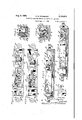
- Fig. 1 is a plan View of a printing form shown as made ⁇ up of a group of slugs for the printing of aV single return address;
- Fig. 2 is a similar view but showing a printing with Linotype composition, comes from the yfact that the slug bearing the longest type line requiresto be quaddedat the right, While the slugs bearing the shorter type lines require -to be quadded both at the Aleft and right ⁇ in such manner that the shorter -type lines will be centered with reference tothe longest quadded type line. While the commercial Linotype machines are equipped with so-called quadding and centering devices, which permitthe casting of slugs quadded at either or both ends of the type line, these devices nevertheless as Vnow constituted are not susceptible of operation to produce the desired result.
- the slugs Being moved as a unit, the slugs will be-maintained in centered relation to veach other.
- the latter is provided with a relatively fixed gage or abutment against which the leading orleft end of the longest type line ybanks when the slugs Iare shiftedendwise. ⁇
- this gageor abutment is permanently attached to the holder,
- Fig. 3 is a longitudinal vertical section taken through the printing form as shown in Fig. 2;
- Fig. 4 is a vertical longitudinal section similar to that of Fig. 3, but showing the parts before the slugs have .been clamped in position;
- Fig. -5 is a transverse vertical section on the line 5-5 of Fig. 3;
- Fig. o is a transverse vertical section on the line 6-6 of Fig. 3, and showing the manner in Which the printing form is associated with the printing cylinder;
- Fig. '7 is aperspective view of a removable gage -or abutment which serves for the location of the slugs in their proper positions in the printing form;
- Fig. 8 is a plan View of an alternative printing form
- Fig. 9 is a longitudinal vertical section taken Ythrough the alternative printing form shown in Flei; Y
- Fig. l isa ⁇ transverse,vertical section taken yon the -line vISD- Ill of Fig..8 ⁇ ;
- Fig. 11 illustratesa series oi envelopes on ⁇ which returnY ⁇ addresses, the lines of which vary in length one from the other,jha ve been printed by means i of the present improvements.
- All ofthe Vs lugs Z are cast with type lines e centered ontheslug body, it beingnoted that the ⁇ type linespresent end ⁇ shoulders e1 risingfrom the blank or quadded portion of the slugs.
- the slugs maybe castinanysuitable machine equipped.
- the base portion A has upwardly extending lateral portions A5 tting into corresponding recesses A6 formed in the side members A1, A2, the parts being detachably secured together by screws a.
- a slug supporting slide C bottomed upon the base portion A and constrained to move longitudinally of the frame by the side members A1 and A2, which at their bottom edges engage in parallel longitudinal grooves C1 formed in the lateral edges of the slide C (see Fig. 5).
- the slide is formed in its underside with a centrally located semi-circular recess C2 which accommodates a spring C3, secured at one end to the slide by a pin. c and anchored at its other end to a pin c1 Xed in the base portion A, the arrangement being such that the slide C is normally urged to the right.
- the slugs are confined within the holder between a jaw C1 xed to the left end of the slide C and a jaw C5 adjustable with the respect to the slide, the latter jaw being carried by a movable member C6 connected by a dove-tailed tongue and groove A7 to the inner face of the side member A2.
- the jaw C5 is held in its different positions of adjustment with respect to the slide C 'by another movable member C7 connected by a dove-tailed tongue and groove A8 to the other side member A1.
- the member C7 is held in its different positions of adjustment with respect to the slide C by a spring-pressed pawl C8 carried by said member and cooperating with a set of ratchet teeth C9 formed on the top face of the slide C adjacent the right end thereof.
- a setscrew C10 threaded through the member C7, banks against the outer face of the jaw C5.
- the jaw carrying member C6 and the pawl carrying member C7 may be adjusted as a unit until the jaw C5 banks against the slugs Z, whereupon the jaw may be tightened through the medium of the set-screw C10, the member C7 of course being held against movement by the pawl C8.
- the jaws C1 and C5 are formed at the top With inclined inner faces c2 and that the slugs Z are correspondingly beveled at their ends to t (Fig. 3), the reason being to prevent the slugs from falling out of the holder when the latter is mounted in the printing cylinder B.
- the top surface of the slide C upon which the slugs stand (Fig. 5) is curved transversely of the holder, as at c3, and also that the inner face of the side member A2 is disposed perpendicularly to the curved surface c3, this arrangement insuring that the printing surface of the slugs will be parallel to the surface of the printing cylinder B when the holder is secured therein (Fig. 6).
- slugs from which a return address is to be printed and which have been cast with the type lines centered thereon, are inserted in the holder on the supporting slide C as shown in Fig. 4. Thereupon, the jaw carrying member C5 and the pawl carrying member C7 are moved to the left until the clamping jaw C5 comes into engagement with the beveled ends of the slug bodies, the pawl C8 acting automatically to hold the parts in their adjusted position. A slight turn of the set-screw C will then take up any play in the ratchet teeth C9 and rmly press the jaw C5 against the slugs.
- the supporting slide C which carries with it the entire group of slugs as clamped between the jaws C4 and C5, is moved to the left against the tension of the spring C3 until the shoulder a1 at the left or leading end of the longest type line in the group of slugs banks. against a transverse bridge member or abutment D previously placed in a xed predetermined position in the holder (see Figs. 1 to 3).
- the bridge ⁇ member D as ⁇ best shown in Fig.
- the holder comprises a frame having a base portion F, side portions F1 and F2, and end portions F3, the latter being provided with drilled retaining lugs F1 by which the holder is secured to the printing cylinder, as in the iirst embodiment.
- the slide C before described is dispensed with and the slugs maintained in alinement with their type portions on a common center line by means of vertical interengaging tongue and groove portions e2 formed G like the bridge member D of the first embodiment serves to locate the slugs in the frame by the banking thereagainst of the left end of the longest type line, but in this instance the bridge member G is permanently secured to the side members of the frameby screws G1.
- the bridge member also serves (in place of the jaw C4 of the first embodiment) to hold the slugs in the frame at their left ends during the printing operation, it being noted, in this connection, that the top surface of the bridge member comes below the printing surface of the slugs so as not to interfere with the printing operation.
- the slugs are held in the frame at their right ends by a clamping jaw H, the active face of which is beveled to cooperate with corresponding beveled portions formed on the top edges of slugs.
- the clamping jaw H has a lower horizontal portion H2 slidably iitted into a square hole H3 formed in a buttress member H5 which is adjustable to various positions depending upon the length of the lines on the slugs.
- the buttress member H5 has a base portion extending the full width of the frame base F between the side members F1 and F2 and an upper portion H6 formed at the sides with tongues I-Irl inclining downwardly toward the right and adapted to cooperate with one pair or another of a series of correspondingly inclined grooves or notches H8 formed in the inner opposed faces of the side members.
- the selection of the grooves H8 depends upon the length of the longest line in the series and, when the buttress member has been located, the clamp H is pressed tightly against the slugs by a setscrevv H9 threaded through the buttress member and banking against the ⁇ clamping member H at the right.
- a printing form holder for supporting a group of printing slugs having their type lines centered with respect to each other, said slugs being adjustable endwise as a unit to position them with one end of the longest type line in a given location ⁇ in the holder.
- a printing form holder for supporting a group of printing slugs having their type lines centered with respect to each other, said slugs being adjustable endwise as a unit to position them with oneend of the longest type line in a given location in the holder, said holder being provided with means for locking up the slugs in their adjusted position.
- a printing form holder for supporting a group of printing slugs having their type lines centered with respect to each other and provided with an abutment set in a given location in the holder, said slugs being adjustable endwise as a unit to a position determined by the engagement of one end of the longest type line with said abutment.
- a printing form holder for supporting a group of printing slugs having their type lines centered with respect to each other and provided with an abutment set in a given location in the holder, said slugs being adjustable endwise as a unit to a position determined by the engagement of one end of the longest type line with said abut- ⁇ ment, and means for locking up the slugs in their adjusted position.
- a printing form holder for supporting a group of printing slugs having their type lines centered with respect to each other and provided with devices for conning the centered slugs therein, said slugs being adjustable endwise as a unit to position them with the end of the longest type line in a given location in the holder.
- a printing form holder according to claim 5, wherein the slug confining devices include an element for determining the given location of the end of the longest type line.
- a printing form holder including, in combination, an open top frame, and a supporting slide in said frame upon which the slugs are clamped in end body alinement with their type lines centered with respect to each other, said slide being adjustable endwise toposition the slugs with one end of the longest type line in a given location in the holder.
- a printing form holder including, in combination, an open top frame, a supporting slide in said frame upon which the slugs are clamped in end body alinement with their type lines centered with respect to each other, an abutment set in a given location in said frame, Spring means for urging the slid-e away from said abutment, and means for setting the slide against the tension of the spring in a position determined by the banking of one end of the longest type line against said abutment.
- a printing form holder including, in combination, van open top frame, a supporting slide in said frame upon which the slugs are clamped i in end body alinement with their type lines centered with respect to each other, an abutment set in a given location in said frame, spring means for urging the slide away from said abutment, means for setting the slide against the tension of the spring in a position determined by the banking of one end of the longest type line against said abutment, and means for locking up the slugs in the adjusted position of the slide.
- a printing form holder including, in combination, an open top frame, a supporting slide in said frame, clamping means including devices carried by the frame, but cooperating with the slide and arranged to hold the slugs upon said slide with their type lines centered with respect to each other, said slide being adjustable to a position determined by the banking of one end of the longest line against an abutment having a xed location in the frame, and means acting through said devices and cooperating with the frame to hold the slide in its adjusted position.
- a printing form comprising a series of slugs rformede'aoh with type lines of varyinglengths centered upon the respective slugs and with interlocking devices for maintaining the slugs centered with respect to each other, and a holder equipped -with a fixed abutment against which the slugs are adapted to be positioned endwise with one end of the longest type line in engagement with said abutment.
- a printing form comprising a series of slugs formed each with type lines of varying lengths centered upon the respective slugs and with interlocking devices for maintaining the slugs centered with respect to each other, and a holder Vequipped with means for setting the slugs endwise with one end of the longest type line in a given location in the printing form.
- the method.V of preparing a printing form from a groupof equal length slugs with centered type lines which consists in arranging the slugs in end body alinement, shifting the slugs endwise as a unit to position them with the end of the longest type line in a given location in the printing form, and then locking up the slugs in their adjusted position.
- the method of preparing a printing form from a group of equal length slugs with centered type lines which consists in arranging the slugs in end body alinement within a suitable holder, shifting the slugs endwise as a unit in the holder to position them with the end of the longest type line in a given location, and then locking up the slugs in their adjusted position.
Landscapes
- Supply, Installation And Extraction Of Printed Sheets Or Plates (AREA)
Description
Aug.v 2, 1938.
G. P.'K INGSBURY PRINTING FORM AND METHOD oF PREPAEING THE SAME Filed Sept. 14, 1936 2 Shee'cs--Sheei'l 1 fh/////// m ...l
www
Augf 2, 193s.
G. P. KlNGSBURY PRINTING FORM AND METHOD OF PREPARING THE SAME Filed Sept. 14, 1936 2 sheets-sheet 2 /N VENTOR A `from/15* xs' culty, as Will be appreciated by those lfamiliar Aso Patented ug. 2, 1938 'UNITED sTArEs PATENT oFFicE RM AND METHOD OF PREPAR- ING THE SAME George P. Kingsbury, Hollis, N. Y., assigner to Mergenthaler Linotype Company, a corpora- `tion of New York Application September 14, 1936, Serial No. 100,662
18 Claims. (Cl. 199,-49)
This invention lrelates to printing forms and to the -method of preparing the same and contemplates certain improvements vwhich -are intended `more particularly foruse in printing return addresses on envelopes.
As a rule, the return address on an `envelope consists of three or -four printed lines varying in length but centered with 4respect Yto each other, and with the longest line spaced atV a given distance from the left-hand end of the envelope. The preparation of printing forms for such Work, when made up of type bars or slugs such das are cast in the commercial Linotype machines, is attended with considerable difficulty, involving slow, tedious and painstaking work. This diiii- PRINTING FO Awhile in another ,embodiment it is designed to be removed after it has subserved its locating function. Once the slugs are properly located in the printing form, they are then locked up in the customary fashion .and the form is ready for use.
In the drawings the .printing form is shown as containing a single groupv of .slugs for the printing of one return address, and moreover it is illustrated asbeing of the fudge box variety `suitable for mounting directly upon the printing cylinder `oi" a rotary press, but it will be understood that the invention is not limited in such respects.`
Referring to the drawings:
Fig. 1 is a plan View of a printing form shown as made `up of a group of slugs for the printing of aV single return address;
Fig. 2 is a similar view but showing a printing with Linotype composition, comes from the yfact that the slug bearing the longest type line requiresto be quaddedat the right, While the slugs bearing the shorter type lines require -to be quadded both at the Aleft and right `in such manner that the shorter -type lines will be centered with reference tothe longest quadded type line. While the commercial Linotype machines are equipped with so-called quadding and centering devices, which permitthe casting of slugs quadded at either or both ends of the type line, these devices nevertheless as Vnow constituted are not susceptible of operation to produce the desired result.
In order to overcome the foregoing Yand other diculties, it is proposed according to -the present invention to provide a printing form which will permit all of the slugs employed for the printing of the return address to be cast with type lines centered thereon regardless of the actual length of the respective lines. Accordingly, it is possible by conditioning the commercial machines for centering to cast such slugs with the-same ease and facility as any other slug. After the slugs have been cast with their centered Atype lines, they are then placed in a suitable -holder .and thereafter shifted endwise as a unit to locate the leading or left end of the longest type line in the required printing position, i. e., in the position necessary to produce the marginal spacing on -the envelope. Being moved as a unit, the slugs will be-maintained in centered relation to veach other. To facilitate -the location of the slugs in the holder, the latter is provided with a relatively fixed gage or abutment against which the leading orleft end of the longest type line ybanks when the slugs Iare shiftedendwise.` In `one of the embodiments illustrated this gageor abutmentis permanently attached to the holder,
the printing of a .different return address;
Fig. 3 is a longitudinal vertical section taken through the printing form as shown in Fig. 2;
Fig. 4 is a vertical longitudinal section similar to that of Fig. 3, but showing the parts before the slugs have .been clamped in position;
Fig. -5 is a transverse vertical section on the line 5-5 of Fig. 3;
Fig. ois a transverse vertical section on the line 6-6 of Fig. 3, and showing the manner in Which the printing form is associated with the printing cylinder;
Fig. '7 is aperspective view of a removable gage -or abutment which serves for the location of the slugs in their proper positions in the printing form;
Fig. 8 is a plan View of an alternative printing form;
Fig. 9 is a longitudinal vertical section taken Ythrough the alternative printing form shown in Flei; Y
Fig. l ,isa `transverse,vertical section taken yon the -line vISD- Ill of Fig..8`; and
Fig. 11 illustratesa series oi envelopes on `which returnY` addresses, the lines of which vary in length one from the other,jha ve been printed by means i of the present improvements.
The.improvedprinting,formcomprises a group oftype'iars` or slugs- Zand a suitable holder in which the slugs are movable in the manner before ,stated and locked up for printing.
, All ofthe Vs lugs Z are cast with type lines e centered ontheslug body, it beingnoted that the `type linespresent end` shoulders e1 risingfrom the blank or quadded portion of the slugs. The slugs maybe castinanysuitable machine equipped.Y
form as made up of another group of slugs for with a line centering mechanism, but see in particular the Frolander U. S. Patent No. 1,971,400
which shows and describes a commercial Linotype sides with lugs A4 drilled to receive fasteningV elements for securing the frame in a printing cylinder B (Fig. 6). Actually, the base portion A has upwardly extending lateral portions A5 tting into corresponding recesses A6 formed in the side members A1, A2, the parts being detachably secured together by screws a.
Within the box-like frame is a slug supporting slide C bottomed upon the base portion A and constrained to move longitudinally of the frame by the side members A1 and A2, which at their bottom edges engage in parallel longitudinal grooves C1 formed in the lateral edges of the slide C (see Fig. 5). The slide is formed in its underside with a centrally located semi-circular recess C2 which accommodates a spring C3, secured at one end to the slide by a pin. c and anchored at its other end to a pin c1 Xed in the base portion A, the arrangement being such that the slide C is normally urged to the right.
The slugs are confined within the holder between a jaw C1 xed to the left end of the slide C and a jaw C5 adjustable with the respect to the slide, the latter jaw being carried by a movable member C6 connected by a dove-tailed tongue and groove A7 to the inner face of the side member A2. The jaw C5 is held in its different positions of adjustment with respect to the slide C 'by another movable member C7 connected by a dove-tailed tongue and groove A8 to the other side member A1. The member C7 is held in its different positions of adjustment with respect to the slide C by a spring-pressed pawl C8 carried by said member and cooperating with a set of ratchet teeth C9 formed on the top face of the slide C adjacent the right end thereof. A setscrew C10, threaded through the member C7, banks against the outer face of the jaw C5. According to this arrangement, the jaw carrying member C6 and the pawl carrying member C7 may be adjusted as a unit until the jaw C5 banks against the slugs Z, whereupon the jaw may be tightened through the medium of the set-screw C10, the member C7 of course being held against movement by the pawl C8. Toremove the slugs Z from between the clamps, it is necessary only to back away the set-screw C1o and lift the pawl C8 out of engagement with the ratchet teeth C9, a nger C11 formed integrally with the pawl C8 being provided for the purpose.
It will be noted that the jaws C1 and C5 are formed at the top With inclined inner faces c2 and that the slugs Z are correspondingly beveled at their ends to t (Fig. 3), the reason being to prevent the slugs from falling out of the holder when the latter is mounted in the printing cylinder B. It will be further noted that the top surface of the slide C upon which the slugs stand (Fig. 5) is curved transversely of the holder, as at c3, and also that the inner face of the side member A2 is disposed perpendicularly to the curved surface c3, this arrangement insuring that the printing surface of the slugs will be parallel to the surface of the printing cylinder B when the holder is secured therein (Fig. 6).
In preparing the printing form, a group of `in print in centered relation. jshown in Fig. 11, three envelopes I, 2 and 3 with three different return addresses printed thereon, v
slugs, from which a return address is to be printed and which have been cast with the type lines centered thereon, are inserted in the holder on the supporting slide C as shown in Fig. 4. Thereupon, the jaw carrying member C5 and the pawl carrying member C7 are moved to the left until the clamping jaw C5 comes into engagement with the beveled ends of the slug bodies, the pawl C8 acting automatically to hold the parts in their adjusted position. A slight turn of the set-screw C will then take up any play in the ratchet teeth C9 and rmly press the jaw C5 against the slugs. Now the supporting slide C, which carries with it the entire group of slugs as clamped between the jaws C4 and C5, is moved to the left against the tension of the spring C3 until the shoulder a1 at the left or leading end of the longest type line in the group of slugs banks. against a transverse bridge member or abutment D previously placed in a xed predetermined position in the holder (see Figs. 1 to 3). The bridge` member D, as` best shown in Fig. 5, has a curved under-surface D1 following the curvature of the upper printing edges of the slugs, and is formed at its opposite ends with a pair of tapered legs D2 arranged to seat in a pair of correspondingly tapered notches A9 formed in the outer faces of the side members A1 and A2 at the top. The slide C is next locked inthe position determined by the bridge member by means of a knurled thumb screw C12 threaded through the member C7 and engaging against the base of the dove-tailed groove in the side member A1, the bridge member thereafter being removed. The slugs are finally locked up in printing form in the usual Way by a pair of quoins E which serve to clamp the slugs firmly against the side member A2. lThe assembled printing form is now ready for use and can be mounted in the printing cylinder B (Fig. 6) Whenever the 'printing is to be proceeded with.
It will have been understood that, since the bridge member D has a xed predetermined location in the holder, the leading end of the longest type line, regardless of its actual length, will likewise have a correspondingly xed predetermined location in the holder or printing form, and this whether it is the rst, second or other slug in the group. And since the type lines are centered on all of the slugs and the slugs, being of equal length, are maintained in end alinement in the holder, all of the lines` will appear Thus, there are and it will be observed that, while the center lines la, 2a and 3a of the diierent addresses vary in location, the longest line of each has the same marginal location, as indicated by the datum line 4 4 (determined by the setting of the bridge member D).
In the alternative embodiment of the invention shown in Figs. 8, 9 and 10, the holder comprises a frame having a base portion F, side portions F1 and F2, and end portions F3, the latter being provided with drilled retaining lugs F1 by which the holder is secured to the printing cylinder, as in the iirst embodiment. In this second embodiment, however, the slide C before described is dispensed with and the slugs maintained in alinement with their type portions on a common center line by means of vertical interengaging tongue and groove portions e2 formed G like the bridge member D of the first embodiment serves to locate the slugs in the frame by the banking thereagainst of the left end of the longest type line, but in this instance the bridge member G is permanently secured to the side members of the frameby screws G1. In addition to locating the slugs, the bridge member also serves (in place of the jaw C4 of the first embodiment) to hold the slugs in the frame at their left ends during the printing operation, it being noted, in this connection, that the top surface of the bridge member comes below the printing surface of the slugs so as not to interfere with the printing operation.
The slugs are held in the frame at their right ends by a clamping jaw H, the active face of which is beveled to cooperate with corresponding beveled portions formed on the top edges of slugs. The clamping jaw H has a lower horizontal portion H2 slidably iitted into a square hole H3 formed in a buttress member H5 which is adjustable to various positions depending upon the length of the lines on the slugs. The buttress member H5 has a base portion extending the full width of the frame base F between the side members F1 and F2 and an upper portion H6 formed at the sides with tongues I-Irl inclining downwardly toward the right and adapted to cooperate with one pair or another of a series of correspondingly inclined grooves or notches H8 formed in the inner opposed faces of the side members. The selection of the grooves H8 depends upon the length of the longest line in the series and, when the buttress member has been located, the clamp H is pressed tightly against the slugs by a setscrevv H9 threaded through the buttress member and banking against the` clamping member H at the right. The reaction against the set-screw presented by the slugs tends to press thebuttress member H5 firmly against the base F of the frame by virtue of the direction of inclination of the cooperating tongue and groove portions. After the slugs have thus been properly located longitudinally, they are firmly clamped against the side member F1 by a pair of quoins J similar to the quoins E in theV first embodiment. The modied holder, as far as printing is concerned, operates in the same manner as the one previously described.
In the accompanying drawings, the invention has been shown merely by way of example and in referred form, and obviously, many variations and modifications may be made therein which will still be comprised within its spirit. It is to be understood, therefore, that the invention is not limited to any specific form or embodiment, except insofar as such limitations are specied in the appended claims.
Having thus described my invention, what I claim is:
l. A printing form holder for supporting a group of printing slugs having their type lines centered with respect to each other, said slugs being adjustable endwise as a unit to position them with one end of the longest type line in a given location` in the holder.
2. A printing form holder for supporting a group of printing slugs having their type lines centered with respect to each other, said slugs being adjustable endwise as a unit to position them with oneend of the longest type line in a given location in the holder, said holder being provided with means for locking up the slugs in their adjusted position.
3. A printing form holder for supporting a group of printing slugs having their type lines centered with respect to each other and provided with an abutment set in a given location in the holder, said slugs being adjustable endwise as a unit to a position determined by the engagement of one end of the longest type line with said abutment.
4. A printing form holder for supporting a group of printing slugs having their type lines centered with respect to each other and provided with an abutment set in a given location in the holder, said slugs being adjustable endwise as a unit to a position determined by the engagement of one end of the longest type line with said abut- `ment, and means for locking up the slugs in their adjusted position.
5. A printing form holder for supporting a group of printing slugs having their type lines centered with respect to each other and provided with devices for conning the centered slugs therein, said slugs being adjustable endwise as a unit to position them with the end of the longest type line in a given location in the holder.
6. A printing form holder according to claim 5, wherein the slug confining devices include an element for determining the given location of the end of the longest type line.
'7. A printing form holder according to claim 5, wherein the given location of the -end of the longest type line is determined by anabutment removable from the holder after the endwise adjustment of the slugs.
8. A printing form holder including, in combination, an open top frame, and a supporting slide in said frame upon which the slugs are clamped in end body alinement with their type lines centered with respect to each other, said slide being adjustable endwise toposition the slugs with one end of the longest type line in a given location in the holder.
9. A printing form holder including, in combination, an open top frame, a supporting slide in said frame upon which the slugs are clamped in end body alinement with their type lines centered with respect to each other, an abutment set in a given location in said frame, Spring means for urging the slid-e away from said abutment, and means for setting the slide against the tension of the spring in a position determined by the banking of one end of the longest type line against said abutment.
10. A printing form holder including, in combination, van open top frame, a supporting slide in said frame upon which the slugs are clamped i in end body alinement with their type lines centered with respect to each other, an abutment set in a given location in said frame, spring means for urging the slide away from said abutment, means for setting the slide against the tension of the spring in a position determined by the banking of one end of the longest type line against said abutment, and means for locking up the slugs in the adjusted position of the slide.
V11. A printing form holder including, in combination, an open top frame, a supporting slide in said frame, clamping means including devices carried by the frame, but cooperating with the slide and arranged to hold the slugs upon said slide with their type lines centered with respect to each other, said slide being adjustable to a position determined by the banking of one end of the longest line against an abutment having a xed location in the frame, and means acting through said devices and cooperating with the frame to hold the slide in its adjusted position.
12. A printing form comprising a series of slugs rformede'aoh with type lines of varyinglengths centered upon the respective slugs and with interlocking devices for maintaining the slugs centered with respect to each other, and a holder equipped -with a fixed abutment against which the slugs are adapted to be positioned endwise with one end of the longest type line in engagement with said abutment.
13. A printing form comprising a series of slugs formed each with type lines of varying lengths centered upon the respective slugs and with interlocking devices for maintaining the slugs centered with respect to each other, and a holder Vequipped with means for setting the slugs endwise with one end of the longest type line in a given location in the printing form.
14. The method of preparing a printing form from a group of slugs with centered type lines, which consists in positioning the slugs as a unit While maintaining their type lines in centered relation With the end of the longest type line in a given location inthe printing form, and then locking up the slugs in said position.
151 The method of preparing a printing form from a group of slugs with centered type lines, which consists in shifting the slugs endwise as a unit while maintaining their type lines in centered relation to position them with the end of the longestA type vline in agiven location in the printing form, 'and then locking up the slugs in their adjusted position.
16. The method.V of preparing a printing form from a groupof equal length slugs with centered type lines, which consists in arranging the slugs in end body alinement, shifting the slugs endwise as a unit to position them with the end of the longest type line in a given location in the printing form, and then locking up the slugs in their adjusted position.
17. The method of preparing a printing form from a group of equal length slugs with centered type lines, which consists in arranging the slugs in end body alinement within a suitable holder, shifting the slugs endwise as a unit in the holder to position them with the end of the longest type line in a given location, and then locking up the slugs in their adjusted position.
18. A printing form according to claim 12, wherein the slugs to constitute the interlocking devices therein referred to, are each formed in one side with a tongue and in the other side with a groove, both of which are perpendicular to the printing edge of the slug, said tongue and said groove being adapted to t a complementary groove and a complementary tongue formed respectively in each two adjacent slugs of the printing form.
GEORGE P. KINGSBURY.
Priority Applications (1)
| Application Number | Priority Date | Filing Date | Title |
|---|---|---|---|
| US100662A US2125676A (en) | 1936-09-14 | 1936-09-14 | Printing form and method of preparing the same |
Applications Claiming Priority (1)
| Application Number | Priority Date | Filing Date | Title |
|---|---|---|---|
| US100662A US2125676A (en) | 1936-09-14 | 1936-09-14 | Printing form and method of preparing the same |
Publications (1)
| Publication Number | Publication Date |
|---|---|
| US2125676A true US2125676A (en) | 1938-08-02 |
Family
ID=22280885
Family Applications (1)
| Application Number | Title | Priority Date | Filing Date |
|---|---|---|---|
| US100662A Expired - Lifetime US2125676A (en) | 1936-09-14 | 1936-09-14 | Printing form and method of preparing the same |
Country Status (1)
| Country | Link |
|---|---|
| US (1) | US2125676A (en) |
-
1936
- 1936-09-14 US US100662A patent/US2125676A/en not_active Expired - Lifetime
Similar Documents
| Publication | Publication Date | Title |
|---|---|---|
| US2125676A (en) | Printing form and method of preparing the same | |
| US1139984A (en) | Imposing-table and proof-press. | |
| USRE16977E (en) | Stamping machine | |
| US2032820A (en) | Key machine | |
| US2038750A (en) | Slug casting machine | |
| US619209A (en) | Harry nathan | |
| US1232718A (en) | Method of making type-bars. | |
| US1276268A (en) | Typograph mechanism. | |
| US1629328A (en) | Beam compass | |
| US809229A (en) | Printing-plate holder. | |
| US2652145A (en) | Matrix assembly stick | |
| US1228736A (en) | Machine for marking golf-balls. | |
| US1056839A (en) | Means for positioning typographic surfaces. | |
| US2011092A (en) | Type bar and holder therefor | |
| US1886772A (en) | Matrix assembly for typesetting machines | |
| US1676602A (en) | Method oe forming- molds fob pb | |
| US2286087A (en) | Printing apparatus and attachment therefor | |
| US1551367A (en) | James cabb | |
| US2785629A (en) | Printer's chase | |
| US1095150A (en) | Adjustable printing-plate holder. | |
| US1131866A (en) | Type-carrier and marking-machine. | |
| US1979045A (en) | Printing device | |
| US2023557A (en) | Slug casting machine | |
| US609883A (en) | Office | |
| US1300846A (en) | Apparatus for preparing type-bars or slugs for use in printing-forms. |