US2125592A - Form for making rubber articles - Google Patents
Form for making rubber articles Download PDFInfo
- Publication number
- US2125592A US2125592A US53923A US5392335A US2125592A US 2125592 A US2125592 A US 2125592A US 53923 A US53923 A US 53923A US 5392335 A US5392335 A US 5392335A US 2125592 A US2125592 A US 2125592A
- Authority
- US
- United States
- Prior art keywords
- cap
- rubber
- strip
- abrupt
- head
- Prior art date
- Legal status (The legal status is an assumption and is not a legal conclusion. Google has not performed a legal analysis and makes no representation as to the accuracy of the status listed.)
- Expired - Lifetime
Links
Images
Classifications
-
- B—PERFORMING OPERATIONS; TRANSPORTING
- B29—WORKING OF PLASTICS; WORKING OF SUBSTANCES IN A PLASTIC STATE IN GENERAL
- B29C—SHAPING OR JOINING OF PLASTICS; SHAPING OF MATERIAL IN A PLASTIC STATE, NOT OTHERWISE PROVIDED FOR; AFTER-TREATMENT OF THE SHAPED PRODUCTS, e.g. REPAIRING
- B29C41/00—Shaping by coating a mould, core or other substrate, i.e. by depositing material and stripping-off the shaped article; Apparatus therefor
- B29C41/34—Component parts, details or accessories; Auxiliary operations
- B29C41/38—Moulds, cores or other substrates
-
- B—PERFORMING OPERATIONS; TRANSPORTING
- B29—WORKING OF PLASTICS; WORKING OF SUBSTANCES IN A PLASTIC STATE IN GENERAL
- B29C—SHAPING OR JOINING OF PLASTICS; SHAPING OF MATERIAL IN A PLASTIC STATE, NOT OTHERWISE PROVIDED FOR; AFTER-TREATMENT OF THE SHAPED PRODUCTS, e.g. REPAIRING
- B29C41/00—Shaping by coating a mould, core or other substrate, i.e. by depositing material and stripping-off the shaped article; Apparatus therefor
- B29C41/02—Shaping by coating a mould, core or other substrate, i.e. by depositing material and stripping-off the shaped article; Apparatus therefor for making articles of definite length, i.e. discrete articles
- B29C41/14—Dipping a core
-
- B—PERFORMING OPERATIONS; TRANSPORTING
- B29—WORKING OF PLASTICS; WORKING OF SUBSTANCES IN A PLASTIC STATE IN GENERAL
- B29K—INDEXING SCHEME ASSOCIATED WITH SUBCLASSES B29B, B29C OR B29D, RELATING TO MOULDING MATERIALS OR TO MATERIALS FOR MOULDS, REINFORCEMENTS, FILLERS OR PREFORMED PARTS, e.g. INSERTS
- B29K2021/00—Use of unspecified rubbers as moulding material
Definitions
- This invention relates to fcrms for making rubber articles and more particularly to forms for making rubber bathing caps and the like.
- a dipped rubber bathing cap with a strip constituting a part thereof which can be tied about the wearer's head whereby a 11 more efiicient water seal between the edge of the cap and the head of the weareris obtained and whereby various decorative and style effects may be obtained with the cap.
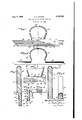
- Fig. 1 is a front elevation and Fig. 2 is a fragmentary rear elevation ofa form on which a rubber cap' and a strip integral there-- with as well as a second independent strip, can be made;
- Fig. 3 is a vertical section of this form with acap thereon, taken'substantially on the line 3-3 of Fig. 1 illustrating how a second strip can be made on the form at the same time that the cap and its integral strip aremade;
- Fig. 4 is a fragmentary cross sectional view of this form taken substantially onthe line 44 of. Fig. 2; and Fig.
- Fig. 5 is a vertical section of this form taken on the line 55 also of Fig. 2;
- Fig. 6 is a front I elevation of a still further modified form on which a rubber cap and tying strips integral there- With can be made;
- Fig. 7 is a vertical section of this last-mentioned form with a cap thereon, taken substantially on the 1ine 1'l of Fig. 6 and
- Fig. 8 is a different vertical section of this form witha cap thereon, taken substantially on the line 88 of Fig. 6.
- FIG. 1 to 5 there is shown a form on which a cap 51) and a tying strip lb, integral therewith as well as a separate tying strip 1a can be made simultaneously byidepositing rubber thereon.
- This form which is flattened, has
- a head portion of the general outline or shape of the desired cap and is provided at the portion thereof where the head opening is to be generated in the cap, with an abrupt edge 36 above which a reinforcing bead or ridge of rubber 3! accumulates, as best indicated in Fig. 3.
- a stripgenerating portion 38 is connected through a restricted neck 39, to the bottom of the head portion 35.
- the front of the portion 38 is made” ders terminating in abrupt edges 44 and 45 re-- spectively.
- the borders 43 graduallymerge, as indicated at 45, with the abrupt edge 36 of the head portion of the form.
- the rear surface of the-portion 38 is provided, as illustrated in Figs. 2 and 3 with a panel 4!
- This panel which is provided with bosses 48 each terminating in an abrupt edge 49, is similar to the panel (Fig. 1) except that its upper edge is bounded by a raised border 53 with a continuous abrupt edge 56. The ends of this panel are likewise bounded by a raised border With an abrupt edge 52 and the lower edge or the panel terminates in the abrupt edge- 53 in the surface of the panel. W
- the forminay be submerged one or more times in an aqueous dispersion of rubber or the like with,
- the rubber will accumulate as a thickened angular reinforcing ridge, while at the abrupt edges 49, 52 and 56 aline of Weakness will be developed in the layer of rubber.
- the excess rubber is torn away from the layer as far as the abrupt edges 36, 45, 44, and 4
- the extra band on the face of the panel 41 can then be re- PATENT OFF CE" moved from the form and the cap with its attached band which is generated on the panel 46 can also be removed from the form and treated in accordance with the usual practice tc prepare it for market.
- the cap b may be worn with the strip 1b tied about the head to provide a more effective seal against water entering between the margin of the cap and the head of the wearer.
- the strip may be tied in various positions on thelhead to give different style It will be understood that the bosses effects. 7 3 and 54 may be of any decorative shape such diamond-shape, heart shape, circular, etc.-,, to provide similarly shaped openings in the tying strip, the invention not being limited to bosses of the outline shown in the drawing l
- a still further modified type of cap 50 can be generated on the form 51 illustrated in Figs. '6;
- This form whichis flattened,v has the general outline of the desired bathing cap but differs from the form previously described in that the form has extensions" 58 prpjeeting in" V opposite directions from the side edges of the form.
- the upper surfaces of these extensions are rounded as best illustrated in Fig, 8 while the bottom surfaces-thereof, which'are' continue ous with the bottom of theform proper, as well as the bevelled ends of the extensions; are provided with abrupt edges 59*and; 60,-; l.
- the rubber accumulates above the abrupt edges, 59 and Bfi asa reinforcing bead or;
- the portionof the rubber layer on the bottom of the ,form is stripped, away as far as the lines of weakness at abrupt edgesb and 60. Thereafter, theremainder of the layer corn 425 stituting. the cap and the attached strips are ree moved from the form.
- the cap 5c may be worn in much the'same manner as the cap 5b,-
- each extension having an abrupt edge.
- one surfaceof said elongatedtportion being adapted to develop a tyings-trip integral with"the'head cap,v an opposing surface of said elongated pon tionvbeing providedwith edgere'iniorcement gen erating means defining a-second tie strip develop-- ing surface.
- a form comprising a headporti'on terminating in an abrupt edge atone end to develop a reinforced margin on a cap deposited on the head portion, an elongated portion connected to said head portion adjacent said abrupt edge, one surface of said elongated portion merging with the cap developing surface'of the head portion to develop a tie-strip integral with the cap, another surface of said' elongated porti-onhaving rein forcement-generating means thereon defining separate tie-strip developing surface.
- cap witharein forced margin defining a head openingztherein
- an elongated portion having a tying strip developing surface thereon bounded by 'reinforcement'Fgenerat ing means to develop LTD'egraledge reinforce ments on the resulting tying strip, said elongated" portion beingconnected atah intermediate portion thereof to said head portion, said tyingfstrip' developi-ngisurface being spaced" from thereinforcement-generating' means of 'said h-e ad por: tion and merging through; a restrictedare'a' atsaid intermediateportion withsaid cap develop ing surface" adjacent the"reinforcement generating means, Whereby'th'eresultingfcap and'tyingstrip will be i-ntegrallyjoired.
- anelongated portion having a tyingstrip' developing surface thereon bounded by .r'einfor'cem'ent generating means to develop" integral edge' rein fcrcements on the resultingtying strip, raised bosses on said tying strip'developing surface"; said elongated portion being connect'ed'at an interme diate portionthereof to said head portion, said tying strip developing surface being spacedfrom the reinforcement-generating means of saidhe'ad portion and'merging through are'stricted area-at said intermediateyportion with saidfcap developestrip will bejintegrally joined.
Landscapes
- Engineering & Computer Science (AREA)
- Mechanical Engineering (AREA)
- Orthopedics, Nursing, And Contraception (AREA)
Description
' Aug, 2, 1938. N SPANEL 2,125,592
FORM FOR MAKING RUBBER ARTICLES Filed Dec. 11, 1935 442:5 ATTORNEY.
UNITED [STATES Patented Aug. 2, 1938 FORM FOR MAKING RUBBER ARTICLES V I Abraham N. Spanel, Rochester, N. Y. 7 Application December 11, 1 935, Serial-No. 53,923
6. Claims. (01. 18-41) This invention relates to fcrms for making rubber articles and more particularly to forms for making rubber bathing caps and the like.
In the past dipped rubber bathing caps while they have been durable and satisfactory in service, have not always prevented leakage of water between the edge of the cap and the head of the wearer. Furthermore, with such bathing caps it has been difficult to produce decorative patterns thereon or to obtain varied style eflects.
In accordance with the present invention, there is provided a dipped rubber bathing cap with a strip constituting a part thereof which can be tied about the wearer's head whereby a 11 more efiicient water seal between the edge of the cap and the head of the weareris obtained and whereby various decorative and style effects may be obtained with the cap.
The variousfeatures and advantages of the invention will appearfrom the detailed descr'ip tion' and claims when taken with the drawing in which Fig. 1 is a front elevation and Fig. 2 is a fragmentary rear elevation ofa form on which a rubber cap' and a strip integral there-- with as well as a second independent strip, can be made; Fig. 3 is a vertical section of this form with acap thereon, taken'substantially on the line 3-3 of Fig. 1 illustrating how a second strip can be made on the form at the same time that the cap and its integral strip aremade; Fig. 4 is a fragmentary cross sectional view of this form taken substantially onthe line 44 of. Fig. 2; and Fig. 5 is a vertical section of this form taken on the line 55 also of Fig. 2; Fig. 6 is a front I elevation of a still further modified form on which a rubber cap and tying strips integral there- With can be made; Fig. 7 is a vertical section of this last-mentioned form with a cap thereon, taken substantially on the 1ine 1'l of Fig. 6 and Fig. 8 is a different vertical section of this form witha cap thereon, taken substantially on the line 88 of Fig. 6. e
Referring to Figs. 1 to 5, there is shown a form on which a cap 51) and a tying strip lb, integral therewith as well as a separate tying strip 1a can be made simultaneously byidepositing rubber thereon. This form, which is flattened, has
a head portion of the general outline or shape of the desired cap and is provided at the portion thereof where the head opening is to be generated in the cap, with an abrupt edge 36 above which a reinforcing bead or ridge of rubber 3! accumulates, as best indicated in Fig. 3. A stripgenerating portion 38 is connected through a restricted neck 39, to the bottom of the head portion 35. The front of the portion 38 is made" ders terminating in abrupt edges 44 and 45 re-- spectively. It should be noted that the borders 43 graduallymerge, as indicated at 45, with the abrupt edge 36 of the head portion of the form. In order that there will not be a large amount of waste rubber deposited, the rear surface of the-portion 38, is provided, as illustrated in Figs. 2 and 3 with a panel 4! on which a second strip independent from the cap can be deposited. This panel, which is provided with bosses 48 each terminating in an abrupt edge 49, is similar to the panel (Fig. 1) except that its upper edge is bounded by a raised border 53 with a continuous abrupt edge 56. The ends of this panel are likewise bounded by a raised border With an abrupt edge 52 and the lower edge or the panel terminates in the abrupt edge- 53 in the surface of the panel. W
In making a cap and its attached band and also in making a separate band on this form, the forminay be submerged one or more times in an aqueous dispersion of rubber or the like with,
a setting interval between each dip until a layer of rubber of the desired thickness is deposited over the face of the form. The rubber will accumulate above the abrupt edges 36, 44 and 53 to provide a reinforcing bead or ridge of rubber, as indicated at 37 in Fig. 3, while a line of weakness will develop in the rubber layer at these abrupt edges. In the junction between the panel 46 and the bosses 54 and raised borders 42 and 43 the rubber will accumulate as a thickened angular reinforcing ridge while at the abrupt edges 44, and 55 a line of weakness will be developed in the rubber layer. Similarly, in the junction between the panel 4'! and the raised border and the bosses 48, the rubber will accumulate as a thickened angular reinforcing ridge, while at the abrupt edges 49, 52 and 56 aline of Weakness will be developed in the layer of rubber. After the rubber layer thus deposited, has been suitably dried and/or cured, the excess rubber is torn away from the layer as far as the abrupt edges 36, 45, 44, and 4| and on the rear surface of the form as far as the abrupt edges 49, 52, 56 and 53. The extra band on the face of the panel 41can then be re- PATENT OFF CE" moved from the form and the cap with its attached band which is generated on the panel 46 can also be removed from the form and treated in accordance with the usual practice tc prepare it for market. The cap b may be worn with the strip 1b tied about the head to provide a more effective seal against water entering between the margin of the cap and the head of the wearer. The strip may be tied in various positions on thelhead to give different style It will be understood that the bosses effects. 7 3 and 54 may be of any decorative shape such diamond-shape, heart shape, circular, etc.-,, to provide similarly shaped openings in the tying strip, the invention not being limited to bosses of the outline shown in the drawing l A still further modified type of cap 50 can be generated on the form 51 illustrated in Figs. '6;
7 and 8. This form whichis flattened,v has the general outline of the desired bathing cap but differs from the form previously described in that the form has extensions" 58 prpjeeting in" V opposite directions from the side edges of the form. The upper surfaces of these extensions are rounded as best illustrated in Fig, 8 while the bottom surfaces-thereof, which'are' continue ous with the bottom of theform proper, as well as the bevelled ends of the extensions; are provided with abrupt edges 59*and; 60,-; l.
In making I a bathing cap on this form; the form is dipped one or more times until ittis submergedin an aqueous dispersion of rubaergwith a fsetting interval between each clip, to deposit;
a layer of the desiredithickness on the surface of the form. The rubber accumulates above the abrupt edges, 59 and Bfi asa reinforcing bead or;
ridge which is semi oval or semi-pearflsha-ped in cross-section, while at these abrupt edges a line of weakness develops in the rubber" layer; 4% After the deposited layer is suitably dried and/or;
cured, the portionof the rubber layer on the bottom of the ,form is stripped, away as far as the lines of weakness at abrupt edgesb and 60. Thereafter, theremainder of the layer corn 425 stituting. the cap and the attached strips are ree moved from the form. The cap 5c may be worn in much the'same manner as the cap 5b,-
WhatIclaimis: .71. A form on whicha bathing cap-or the like anda tying strip therefor can be deposited simultaneously, saidform com-prising a- -he'ad' portion terminating-in an abrupt edge to ,d'efine'a head! opening in the cap and extensions on said head:
portion extending in opposite directions therefrom, each extension having an abrupt edge.
2. A form-on which abathing cap or the like and tying strips therefor canjbedeposited simul t aneously, saidform comprising a head portion terminatingin an abrupt edge to develop; a-cap with a reinforced margin de fininga head7opening therein, anelongated portion; connected-to said head portion adjacent tosaid abrupt edge,
one surfaceof said elongatedtportion being adapted to develop a tyings-trip integral with"the'head cap,v an opposing surface of said elongated pon tionvbeing providedwith edgere'iniorcement gen erating means defining a-second tie strip develop-- ing surface. f l
A form comprising a headporti'on terminat ing in an abrupt edge atone end to develop a reinforced margin on a cap deposited on the head portion, an elongated portion connected to said head portion adjacent said abrupt edge, one surface of said elongated portion merging with the cap developing surface'of the head portion to develop a tie-strip integral with the cap, another surface of said' elongated porti-onhaving rein forcement-generating means thereon defining separate tie-strip developing surface. 7
' 4. 'A form on which a bathing cap oif the 11kt and a; tying strip integral therewith be deposited simultaneously, said ferm comprising a head portion having a, cap developing surface l provided with a marginal reinforcement-generating means to develop a cap with a reinforced 1 margin defining a head opening therein, an elonposited simultaneously; said form. comprising-ahead" portion having'a cap'developing surface provided with a marginal reinforcement -generating means to develop, a. cap witharein forced margin defining a head openingztherein, an elongated portion having a tying strip developing surface thereon bounded by 'reinforcement'Fgenerat ing means to develop irit'egraledge reinforce ments on the resulting tying strip, said elongated" portion beingconnected atah intermediate portion thereof to said head portion, said tyingfstrip' developi-ngisurface being spaced" from thereinforcement-generating' means of 'said h-e ad por: tion and merging through; a restrictedare'a' atsaid intermediateportion withsaid cap develop ing surface" adjacent the"reinforcement generating means, Whereby'th'eresultingfcap and'tyingstrip will be i-ntegrally joiired.
A form onwhichabathing cap or the and a tying'strip'integral therewith" canr belde posited simultaneously, said form comprising a head portion having 'a" cap'developing surface provided with a marginal reinforoemenvgenerating means to develop a capj witha reinforced.- margin defining a head opening therein;. anelongated portion having a tyingstrip' developing surface thereon bounded by .r'einfor'cem'ent generating means to develop" integral edge' rein fcrcements on the resultingtying strip, raised bosses on said tying strip'developing surface"; said elongated portion being connect'ed'at an interme diate portionthereof to said head portion, said tying strip developing surface being spacedfrom the reinforcement-generating means of saidhe'ad portion and'merging through are'stricted area-at said intermediateyportion with saidfcap developestrip will bejintegrally joined.
ing surface adjacent the reinforcement-generat gmeans',"whereby the' resulting-cap and-' tying BR HAM N; sPANEH
Priority Applications (2)
| Application Number | Priority Date | Filing Date | Title |
|---|---|---|---|
| US53923A US2125592A (en) | 1935-12-11 | 1935-12-11 | Form for making rubber articles |
| US97985A US2147504A (en) | 1935-12-11 | 1936-08-26 | Cap |
Applications Claiming Priority (1)
| Application Number | Priority Date | Filing Date | Title |
|---|---|---|---|
| US53923A US2125592A (en) | 1935-12-11 | 1935-12-11 | Form for making rubber articles |
Publications (1)
| Publication Number | Publication Date |
|---|---|
| US2125592A true US2125592A (en) | 1938-08-02 |
Family
ID=21987474
Family Applications (1)
| Application Number | Title | Priority Date | Filing Date |
|---|---|---|---|
| US53923A Expired - Lifetime US2125592A (en) | 1935-12-11 | 1935-12-11 | Form for making rubber articles |
Country Status (1)
| Country | Link |
|---|---|
| US (1) | US2125592A (en) |
Cited By (1)
| Publication number | Priority date | Publication date | Assignee | Title |
|---|---|---|---|---|
| US3170194A (en) * | 1961-08-14 | 1965-02-23 | Plastomeric Products Corp | Glove mold |
-
1935
- 1935-12-11 US US53923A patent/US2125592A/en not_active Expired - Lifetime
Cited By (1)
| Publication number | Priority date | Publication date | Assignee | Title |
|---|---|---|---|---|
| US3170194A (en) * | 1961-08-14 | 1965-02-23 | Plastomeric Products Corp | Glove mold |
Similar Documents
| Publication | Publication Date | Title |
|---|---|---|
| CA189258S (en) | Headgear and yoke assembly for direct nasal mask assembly | |
| US4573219A (en) | Necktie knot simulator | |
| US2600392A (en) | Shampoo device | |
| US2033065A (en) | Rubber bathing suit | |
| US7272861B2 (en) | Face-mask neck sash | |
| US2125592A (en) | Form for making rubber articles | |
| US1968401A (en) | Clasp for scarfs, neckties, and the like | |
| US2604104A (en) | Toupee | |
| ITFI940133A1 (en) | FIN FOR SWIMMING AND ITS PRODUCTION PROCESS | |
| Corbett | Preliminary sketch in Greek vase-painting | |
| US2175693A (en) | Hair bearing figure and method of making same | |
| US2100576A (en) | Form for making rubber articles | |
| US2032804A (en) | Lather mask | |
| GB2575837A (en) | Template for makeup | |
| US1331527A (en) | Pattern and method of cutting skins or the like | |
| US2068760A (en) | Hat ornament | |
| US1444436A (en) | Porcelain veneer crown and process of making same | |
| US1711402A (en) | Method of making dental crowns | |
| US2413283A (en) | Ear muff | |
| JP2001095956A (en) | Golf club head | |
| JPS6188713U (en) | ||
| US20190014878A1 (en) | Waterproof Hair Accessory | |
| US2100575A (en) | Form for making rubber articles | |
| US2074004A (en) | Pump | |
| US1669732A (en) | Method of and apparatus for attaching flexible retaining margins to artificial dentures |