US2118941A - Gauge feeding means for cutting machines - Google Patents
Gauge feeding means for cutting machines Download PDFInfo
- Publication number
- US2118941A US2118941A US96184A US9618436A US2118941A US 2118941 A US2118941 A US 2118941A US 96184 A US96184 A US 96184A US 9618436 A US9618436 A US 9618436A US 2118941 A US2118941 A US 2118941A
- Authority
- US
- United States
- Prior art keywords
- gauge
- worm
- stack
- shaft
- moving
- Prior art date
- Legal status (The legal status is an assumption and is not a legal conclusion. Google has not performed a legal analysis and makes no representation as to the accuracy of the status listed.)
- Expired - Lifetime
Links
Images

Classifications
-
- B—PERFORMING OPERATIONS; TRANSPORTING
- B26—HAND CUTTING TOOLS; CUTTING; SEVERING
- B26D—CUTTING; DETAILS COMMON TO MACHINES FOR PERFORATING, PUNCHING, CUTTING-OUT, STAMPING-OUT OR SEVERING
- B26D7/00—Details of apparatus for cutting, cutting-out, stamping-out, punching, perforating, or severing by means other than cutting
- B26D7/01—Means for holding or positioning work
- B26D7/015—Means for holding or positioning work for sheet material or piles of sheets
- B26D7/016—Back gauges
-
- Y—GENERAL TAGGING OF NEW TECHNOLOGICAL DEVELOPMENTS; GENERAL TAGGING OF CROSS-SECTIONAL TECHNOLOGIES SPANNING OVER SEVERAL SECTIONS OF THE IPC; TECHNICAL SUBJECTS COVERED BY FORMER USPC CROSS-REFERENCE ART COLLECTIONS [XRACs] AND DIGESTS
- Y10—TECHNICAL SUBJECTS COVERED BY FORMER USPC
- Y10T—TECHNICAL SUBJECTS COVERED BY FORMER US CLASSIFICATION
- Y10T83/00—Cutting
- Y10T83/647—With means to convey work relative to tool station
- Y10T83/6656—Rectilinear movement only
- Y10T83/6657—Tool opposing pusher
- Y10T83/6662—Gear or pulley actuated
Landscapes
- Life Sciences & Earth Sciences (AREA)
- Forests & Forestry (AREA)
- Engineering & Computer Science (AREA)
- Mechanical Engineering (AREA)
- Forming Counted Batches (AREA)
Description
May 31, 1938. M PORTER 2,118,941
GAUGE FEEDING MEANS FOR CUTTING MACHINES Filed Aug. 15, 1936 2 Sheets-Sheet l INVENTOR 650266 M. PORTER ATTO R N EY May 31, 1938.
G. M. PORTER GAUGE FEEDING MEANS FOR CUTTING MACHINES Filed Aug. 15, 1936 2 Sheets-Sheet 2 INVENTO GEORGE M. P02 r? VZWM TTORNEY Patented May 31, 1938 GAUGE FEEDING MEANS FOR CUTTING MACHINES George M. Porter, Brooklyn, N. Y.
Application August 15, 1936, Serial No. 96,184
6 Claims.
The present invention relates to power operated gauges and more particularly to means for moving the gauge of a machine such as a paper cutter of the guillotine type.
Paper cutters of the above-mentioned type are often of large size having tables from 28" to '72" or more across and designed to handle stacks or packs of paper of considerable weight. These packs are prepared for the printing press by cutting them up into the required sizes. Hence, the pack of paper upon the cutter table is moved and slid to positions against and by gauges several times during such cutting operation.
Heretofore, the positioning of the back gauge, against which the stack is positioned, was in nearly all cases accomplished manually through the manipulation of a handle or handwheel. This is quite an arduous and tiring job of work, particularly when it is borne in mind that the machine attendant may be doing this for many consecutive hours. In addition, the operator must first remove from the table the cut-01f portion of the stack before moving the remainder of the stack to a new cutting position.
Paper cutters and certain other machines have been constructed in which power operated gauges were incorporated as an integral whole with the machine. These machines were .quite complicated and costly and included mechanism not particularly adapted as attachments for machines originally constructed for manual operation. As can be well understood, these mechanisms were not adaptable for employment as attachments and hence, one of the problems encountered resided in the provision of simple means quickly applicable, for converting a non-power machine to a power machine.
The invention therefore seeks to obviate the above both arduous and costly methodof handling a paper stack on a cutting machine table by providing power operated means in the form of an attachment, for moving the back gauge and hence the stack, and thereby also shortening the handling time, since cut-off portions. of paper may be removed from the table during the period of operation of said power means.
More specifically, the invention seeks to provide power means for moving a paper stack into approximate position in relation to a cutter, and means affording accurate positioning of the stack by manual final adjustment.
In carrying out the invention, it is contemplated to use a reversible electric motor and reversing switch for moving the stack-positioning back gauge in eitherdirection in relation to the cutter.
The latter is accomplished through the medium of a slow drive such as a worm and worm wheel, and by mounting the worm for sliding movement, the back'gauge may be manually advanced in the direction of its initial travel for accurate setting of said gauge.
The accompanying drawings which are hereinafter described in detail, illustrate preferred arrangements for carrying out the'principles of the invention as at present contemplated.
In the drawings:-
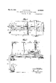
Fig. 1 isa plan View of a guillotine type cutter incorporating features of the invention.
Fig. 2 is a longitudinal sectional view taken approximately through the center of Figure 1.
Fig. 3 is an enlarged fragmentary end view of the intermediate driving means for the back gauge.
Fig. 4 is a top plan view thereof.
Fig. 5 is a view, partly in section, as taken on the line 5-5 of Figure 3.
Fig. 6 is a, fragmentary longitudinal sectional view of an alternate form of intermediate driving mechanism.
In the drawings, the paper cutter bed or table It! is provided with lateral gauge plates H, a back gauge I2, and a guillotine knife or cutter I3.
The back gauge I2 is provided with a connection M to an endless chain l5 trained around a sprocket wheel I! at the other end so that movement of the chain will cause movement of the back gauge along a keyway 18 in the table.
The gauge, in this manner, may be moved by operation of the handwheel IS on the stud 20 upon which the sprocket I6 is mounted.
In order to disclose the position of the back gauge in relation to the knife l3, a graduated tape or band 2|, readable in association with an index 22, is provided, this band being mounted on wheels or drums 23 and 24 at the respective front and rear portions of the machine. The band 2| moves with the back gauge as by means of a connection 25 between the gauge and the band.
As contemplated in this invention, the gauge l2 may be moved as by the following power means.
A reversible electric motor 26 is arranged to drive, through the medium of a belt 21 or the like, a pulley 28 carried on a shaft 29, mounted in a bracket 30, preferably bolted to the underface of the table II).
Upon the shaft 29 there is slidably mounted a worm 3| as by means of key means 32. The worm is arranged to abut either of the opposed shoulder 33 or 34 carried by the bracket and to mesh with a worm wheel 35, also carried by said bracket as by means of the stud 36 to which the sprocket I1 is also fixed.
This assemblage of parts, starting with the pulley 28 and terminating in the sprocket ll, comprise the intermediate power drive means between the motor 26 and the gauge moving chain 15 forming the essence of this invention.
While the invention is shown as applied to a paper cutter having a chain drive for the back gauge, as shown in Figure 6, the invention may also be applied on machines using a screw drive.
In this event, the screw 40 operating to feed the nut 4! which is fixed with the gauge I2, is arranged to be driven by the worm wheel 35 through the medium of miter gears 42.
If desired, the shaft 29 may be extended as at 29 to the front of the machine and provided with a handwheel l9 as shown in Figure 1. In this event the handwheel l9 may be omitted, and the above described sliding of the worm 3|, obviated.
The operation of the device is as follows: A stack of paper P is placed on the table and positioned against the preset back gauge I2 and against one of the lateral gauges H. The knife 13 is then operated in the usual manner to cut through the stack as on the line a.
The motor switch S is then operated to cause the motor 26 to move the gauge I2 and hence the stack towards the knife. Assuming a direction of rotation of the pulley 28 as indicated by the arrow (Figure 4), the worm 3| will drive the worm wheel in a clockwise direction, first, however, assuming a position against the shoulder 33.
During this operation, the attendant may remove the cut-off portion of the stack from the table of the machine. The tape 2|, at the index 22, is watched to obviate an over feed of the gauge, and as the desired reading of said tape approaches the index, the motor 26 is cut out. The gauge, at this time, is not in the required position and in order to place it in the exact position required, the hand wheel I9 is manipulated until the desired mark on the tape 2| is read in association with the index 22. This latter setting of the gauge I2 is readily accomplished since in moving the chain l5 in the direction of its original drive, the worm wheel 35 merely rotates to slide the worm 3| along the shaft 29 and towards the abutment 34. Hence, the initial space between the worm 3| and the shoulder 34, represents the amount of adjustment, the gauge [2 is afforded after the power drive is out out.
The stack is now positioned so the knife will cut through the line b. This process may be continued until the entire stack has been cut up. Now, in order to move the gauge l2 back towards the rear of the machine, the motor switch is operated to cause operation of the motor in the reverse direction. The worm will now assume a position against the shoulder 34 to cause rotation of the worm wheel in a counterclockwise direction. Again the tape 2| is watched so the motor may be stopped before the gauge is in exact position, and again the handwheel I9 is operated to exactly position the gauge in accordance with the tape reading at the index 22.
When the machine is provided with the extension shaft 29 and handwheel Ill the poweroperated portion of the machine is employed as above described and the handwheel I9 utilized for final adjustment to bring the back gauge and thus the stack to position under the knife.
As can be seen from the foregoing, a power operated gauge has been provided in its preferred embodiments; that considerable time and physical effort are saved in its employment; that it may be quickly and inexpensively installed in new and existing machines; and that no great degree of skill is needed to operate it efficiently. However, although disclosed in detail, changes by skilled persons may readily be made without departing from the scope of the invention as claimed. Therefore, the prior art rather than this specific disclosure shown form the basis of interpretation of these claims.
I claim:
1. In combination with a machine having a table and a knife, a member adapted to move and to position a stack on said table in relation to said knife, power operated means for moving said member to an approximate position, manual means for moving said member from the approximate position to an exact position, said power operated means including a driven shaft, a worm rotatable with and slidably mounted on said shaft and means for limiting the slidable movementof said worm.
2. In combination with a machine having a table for the reception of a stack of flat articles and an instrument for operation on said stack, a gauge for one edge of said stack, said gauge being adapted to move and to position said stack in relation to said instrument, power operated means for moving said gauge to an approximate position in relation to said instrument, said means comprising a driven shaft, a worm rotatable with and slidably mounted on said shaft, means for limiting the slidable movement of said Worm, and a member driven by said worm and adapted to slide the worm on its shaft toward one of its limiting means, and manual means for moving said gauge from said approximate position to an exact position in relation to said instrument.
3. In combination with a machine having a table for the reception of. a stack of flat articles and an instrument for operation on said stack, a gauge for one edge of said stack, said gauge being adapted to move and to position said stack in relation to said instrument, power operated means for moving said gauge to an approximate position in relation to said instrument, said means including a driven shaft, a worm rotatable with and slidably mounted on said shaft, a shoulder to each side of the worm for limiting its slidable movement and a Worm Wheel operatively engaged with said worm to be rotated by it, said operative engagement being such that upon operation of the worm wheel the worm will be forced to slide toward one of the mentioned shoulders before the worm can rotate the worm wheel, and manual means for moving said gauge from said approximate position to an exact position in relation to said instrument.
4. In combination With a machine having a table and a knife, a member adapted to move and to position a stack on said table in relation to said knife, power operated means for moving said member to an approximate position, and manual means for moving said member from the approximate position to an exact position, said power operated means including a shaft adapted to be driven in clockwise or counterclockwise direction selectively, a worm rotatable with and slidable on said shaft, a fixed shoulder to each side of the worm for limiting its slidable movement, said worm being adapted to assume a position against one shoulder when said shaft is driven clockwise and against the other shoulder when said shaft is driven counterclockwise.
5. In combination with a machine having a table for the reception of a stack of flat articles and an instrument for operation on said stack, a gauge for one edge of said stack, said gauge being adapted to move and to position said stack in relation to said instrument, power operated means for moving said gauge to an approximate position in relation to said instrument, said power operated means including, a shaft adapted to be driven in clockwise or counterclockwise direction selectively, a worm rotatable with and slidable on said shaft, a fixed shoulder to each side of the worm for limiting its slidable movement, and a worm wheel adapted to be driven by said worm, said worm being adapted to assume a position against one shoulder when said shaft is driven clockwise and against the other shoulder when said shaft is driven counterclockwise, and manual means for moving said gauge from said approximate position to an exact position in relation to said instrument.
6. In combination with a machine having a table for the reception of a stack of flat articles and an instrument for operation on said stack, a gauge for one edge of. said stack, said gauge being adapted to move and to position said stack in relation to said instrument, power operated means for moving said gauge to an approximate position in relation to said instrument, said power operated means comprising an endless chain secured to the gauge, a power of sprockets form ing the end bights of said chain, a bracket mounting one of said sprockets, a worm wheel mounted with said last mentioned sprocket, a worm, a shaft rotationally and slidably mounting said worm, said worm and worm wheel being in driving engagement whereby initial rotation of the worm will cause it to slide, and continued rotation of the worm will cause the worm wheel to rotate, and means for driving said shaft in either direction.
GEORGE M. PORTER.
Priority Applications (1)
| Application Number | Priority Date | Filing Date | Title |
|---|---|---|---|
| US96184A US2118941A (en) | 1936-08-15 | 1936-08-15 | Gauge feeding means for cutting machines |
Applications Claiming Priority (1)
| Application Number | Priority Date | Filing Date | Title |
|---|---|---|---|
| US96184A US2118941A (en) | 1936-08-15 | 1936-08-15 | Gauge feeding means for cutting machines |
Publications (1)
| Publication Number | Publication Date |
|---|---|
| US2118941A true US2118941A (en) | 1938-05-31 |
Family
ID=22256151
Family Applications (1)
| Application Number | Title | Priority Date | Filing Date |
|---|---|---|---|
| US96184A Expired - Lifetime US2118941A (en) | 1936-08-15 | 1936-08-15 | Gauge feeding means for cutting machines |
Country Status (1)
| Country | Link |
|---|---|
| US (1) | US2118941A (en) |
-
1936
- 1936-08-15 US US96184A patent/US2118941A/en not_active Expired - Lifetime
Similar Documents
| Publication | Publication Date | Title |
|---|---|---|
| US3260146A (en) | Double head side trimmer | |
| US3566932A (en) | Process for rational production of size plates with a plate saw, in particular using an electronic control and device for practicing | |
| US1838011A (en) | Mandrel de-corer | |
| US1982880A (en) | Automatic book cutting machine | |
| US2846005A (en) | Trimmer or paper cutter | |
| US2118941A (en) | Gauge feeding means for cutting machines | |
| US1678458A (en) | Multiple shears | |
| US2169517A (en) | Meat sawing machine | |
| US3759124A (en) | Automatic cut-off saw | |
| US2751003A (en) | Sheet feeder | |
| US2164616A (en) | Punching and cutting machine | |
| DE884804C (en) | Machine for finishing stereotype plates | |
| GB1458133A (en) | Continuous business forms stationary processing apparatus | |
| GB1125377A (en) | Rotary knife machine for cutting single or multiple rolls | |
| US1050194A (en) | Machine for cutting sheet metal. | |
| US2786497A (en) | Guide fence for a machine table | |
| US1711275A (en) | Double-end tenoner | |
| US1267283A (en) | Paper-cutting machine. | |
| US2208022A (en) | Machine for cutting sheet metal | |
| US1985500A (en) | Saw mill | |
| US2165953A (en) | Cutting machine | |
| GB1223030A (en) | Grinding machines | |
| US1693361A (en) | Machine for cutting off stock | |
| US1007355A (en) | Combined metal saw and trimmer. | |
| US1566064A (en) | Bacon slicer |