US2118902A - Grinding machine - Google Patents
Grinding machine Download PDFInfo
- Publication number
- US2118902A US2118902A US34148A US3414835A US2118902A US 2118902 A US2118902 A US 2118902A US 34148 A US34148 A US 34148A US 3414835 A US3414835 A US 3414835A US 2118902 A US2118902 A US 2118902A
- Authority
- US
- United States
- Prior art keywords
- shaft
- axis
- grinding
- grinding wheel
- wheel
- Prior art date
- Legal status (The legal status is an assumption and is not a legal conclusion. Google has not performed a legal analysis and makes no representation as to the accuracy of the status listed.)
- Expired - Lifetime
Links
- 230000033001 locomotion Effects 0.000 description 42
- 230000010355 oscillation Effects 0.000 description 40
- 230000008093 supporting effect Effects 0.000 description 22
- 229910003460 diamond Inorganic materials 0.000 description 13
- 239000010432 diamond Substances 0.000 description 13
- 150000001875 compounds Chemical class 0.000 description 5
- 238000010276 construction Methods 0.000 description 5
- 230000003247 decreasing effect Effects 0.000 description 3
- 238000010586 diagram Methods 0.000 description 3
- 238000000034 method Methods 0.000 description 3
- 238000013459 approach Methods 0.000 description 2
- 230000000694 effects Effects 0.000 description 2
- 101150000595 CLMP gene Proteins 0.000 description 1
- 101100382322 Drosophila melanogaster Acam gene Proteins 0.000 description 1
- 230000015572 biosynthetic process Effects 0.000 description 1
- 239000002245 particle Substances 0.000 description 1
- 229920000136 polysorbate Polymers 0.000 description 1
- 210000003813 thumb Anatomy 0.000 description 1
Images


Classifications
-
- B—PERFORMING OPERATIONS; TRANSPORTING
- B24—GRINDING; POLISHING
- B24B—MACHINES, DEVICES, OR PROCESSES FOR GRINDING OR POLISHING; DRESSING OR CONDITIONING OF ABRADING SURFACES; FEEDING OF GRINDING, POLISHING, OR LAPPING AGENTS
- B24B19/00—Single-purpose machines or devices for particular grinding operations not covered by any other main group
- B24B19/02—Single-purpose machines or devices for particular grinding operations not covered by any other main group for grinding grooves, e.g. on shafts, in casings, in tubes, homokinetic joint elements
- B24B19/06—Single-purpose machines or devices for particular grinding operations not covered by any other main group for grinding grooves, e.g. on shafts, in casings, in tubes, homokinetic joint elements for grinding races, e.g. roller races
Definitions
- the invention is illustrated in connection with the formation of elliptical race curvatures for race rings of antiiriction bearings.
- raceway grooves are transversely arcuate and have a radius of curvature which is slightly larger than the radii of the balls.
- These raceways are usually produced on an oscillating grinding machine in which either the work or a grinding wheel is oscillated around a center. It has been found that certain raceway curvatures which are not circularly arcuate have certain advantages in respect to load capacity and endurance when applied to ball bearings, especially elliptical race- Ways wherein the curvature is defined by that part of an ellipse adjacent one end of the major axis. Accuracy of curvature is very important to get the desired advantages, and a departure of even one ten-thousandth part of an inch from the desired curve is'too large an error to be allowable.
- An object of the invention accordingly, is to provide a machine to generate accurately a noncircular curve, especially an elliptical curve. Another object is to produce a predetermined curve on a work-piece without the use of prepared templates and yet to create that curve by simple mechanism and motions which can be accurately its broader aspects, the invention is not necessarily limited to the specific constructions selected for illustrative purposes in the accompanying drawings in which Fig. 1 is a front elevation of 'a grinding machine.
- Fig. 2 is a sectional View on the line 22 of Fig. l but showing some parts broken away at a lower level.
- Fig. 3 is a sectional view on the line 3-3 Fig. l.
- Fig. 4A is a front view of a slide.
- Fig. 5 is a view of portions of Fig. 4 enlarged.
- Fig. 6 is a sectional view on line 6-6 of Fig. 5.
- Fig. 7 is chiefly a vertical sectional view on the line 'l-l of Fig. 4.
- Figs. 8 and 9 are diagrams.
- Fig. 10 is a front elevation, partly broken away and in section, of a grinding machine of modified construction but utilizing the same basic principles of curve generation as in .the preceding figures.
- Fig. 11 is a side elevation of Fig. 10.
- Fig. 12 is a section on the line l2-l2 of Fig. 10.
- Fig. 13 is a section on the line Ill-l3 of Fig. 11.
- Fig. 14 is a section on the line i l-l4 of Fig. 11.
- Figs. 15, 16 and 17 are diagrams.
- this invention utilizes the principle that a particle travel-' ling around the axis of a right cylinder in the surface thereof and also in an inclined plane will generate an ellipse.
- the minor axis of the ellipse is then the diameter of the cylinder and the major axis depends on the inclination.
- the ellipse can be varied to suit the particular bearing by changing the inclination or the diameter or both.
- actual movementof the generating member is controlled by rigidly connected and accurately mounted parts one of which moves in an amplified and hence accurately controlled ellipse which has a known relation to the desired elliptical path of the generating member.
- the curvature' may be directly generated upon the race ring or work itself or maybe generated upon an abrading member which transfers the curve to the work.
- the line A represents the axis of a cylinder, and a generating member D moves around such axis in' an inclined plane represented by the line K having the inclination T which can be selected.
- the generating point moves angularly or oscillates at aselect'ed distance r from the axis while also having a selected vertical travel of an amplitude represented by the line P.
- Fig. 4 is a side elevation of the grinding masmall (though exaggerated. in the diagram), con
- a cam roller 18 travels on a cam represented as an inclined plane H having a selected inclination B.
- the line R represents the distance of the roller contact point from the axis A, and the roller has a vertical travel represented by line P, the roller imparting the same vertical travel to the connected member D.
- the contact point of the roller with the cam also travels in an ellipse E which is more nearly circular than the desired ellipse e but has a predetermined and computable: relation to the latter.
- the generating member or point D may be a diamond for producing a-transverse elliptical 'curve on a grinding wheel which transfers the shape to a work-piece.
- the numeral 2 indicates a frame supportingv a work head 4 which may have any suitable chuck to hold and rotate a workpiece W (indicated by broken lines in Fig. 4) in contact with a grinding wheell
- the grinding wheel 6 is rotatably supported by a head 8 having a cross feed slide I8 controlled by a hand wheel/I2.
- a head 8 having a cross feed slide I8 controlled by a hand wheel/I2.
- Bolted to the rear of the head 8 is an upright bracket I4 whose upper end is provided with arcuate slots I6 for clamping screws I8 which adjustably secure a circular flange28 of an inclined slide base 22.
- the flange 28 has a centering plug 28 entering a circular recessin the bracket I4.
- the slide base has dovetail ways 24 one of which is provided with an adjustable gib 25 secured by screws 28.
- a dovetail tongue or slide 28 projects laterally into the ways from a circular flange 38 which is adjustably secured by clamping screws 82 to a circular flange 84 orf a carrier 36, the flange 34 having arcuate slots similar to the arcuate slots I8.
- the tongue or slide 28 has a nut 31 for a feed screw 88 which is journalled for rotation without endwise move ment in an end plate 48 fastened at the front ofand the slots I 6, a suitable scale 44 co-operating with an index line to show the angularity or inclination.
- a similar scale 48 on the flange 88, but graduated in the opposite direction, indicates the angular adjustment of the flange 84 and the parts carried by the carrier 88, such parts having a corrective angular adjustment to bring the gen-' erating member or diamond D back to the wheel periphery when moved away by adjustment of the inclination of the slide base.
- the carrier 36 (see Fig. '7) has flanged bearing bushings 46 and 48 which support an upright shaft 58 for oscillation and vertical sliding.
- An arm 52 is fastened to the shaft by clamping screws 54, the arm being split as shown in Fig. 2 and having a vertical slot for a key 56 which enters a vertical keyway in the shaft, thus preventing relative rotation but providing for vertical adjustment of the arm on the shaft.
- the arm has a horizontal slot 68 receiving an eccentric 62 which can be turned on a supporting screw 64 projecting from the shaft.
- the latter has a nut-like head 66.
- the clamping screws 54 are clination provided by pivot screws I6 extending into a lug I8 of the carrier 86, ⁇
- the yoke has a wear plug 88 engaging the upperjend of a vertical adjusting screw 82 which is threaded in a web of the carrier 36.
- a lock nut 84 holds the screw 82 in adjusted position with the cam in the selected inclined plane H of Fig. 8.
- the lower end of the shaft 88 has a squared enlargement 98 with slots for clamping screws 92 which adjustably anchor a detachable and replaceable bracket or arm 84 to the shaft.
- the slots provide for lateral adjustment of the bracket, the latter having a guide tongue 86 (Figs. 3 and 5) slidable in a groove of the enlargement 88.
- a pin 88 is driven into a hole of the bracket or arm 84 and has a flattened portion entering a slot in the enlargement.
- Vernier screws I88 are threaded in the enlargement in a position to abut against opposite sides of the flattened portion of the pin.
- a dial I82 is secured to each screw by a clamping screw I84. The foregoing mechanism provides for.
- the bracket or arm 84 has 'a rearwardly oflset and inclined extension I86 for a cone-ended stud 8' which supports the diamond D.
- the stud has a shank secured to a slidable pin II2 which is adjustable endwise in a guide openingof the extension.
- the pin has an annular notch II4 into which projects a collar II6 on an adjusting screw III which is threaded in a tapped opening I28 of the extension I88.
- a dial I22 is flxed to the adjuilting screw by a clamping screw I24.
- This adjustment provides for movement of the diamond D along a radius of the grinding wheel 8 and it also determines the distance of the diamond from the axis of oscillation. In other words, it determines the radius r or horizontal distance of the diamond from the axis A as'indicated in Fig. 8. This distance r is also one half the minor aids of the ellipse e because the point D is always in the surface of a cylinder having the radius r.
- the upper portion of the shaft 58 (see Fig. '1) is reduced in diameter to receive a sleeve I28 which is keyed from rotation on the shaft by a taper "pin I38.
- the sleeve has opposite pairs of elonbeing partly confined in a recess of a skirted housing I48 which is fastened to the carrier 36.
- the hub member is fastened by screws I to a worm Wheel I42 driven by a worm I44 on a shaft I46 which is journalled in lugs I48 on the carrier 86.
- the shaft I46 also carries a worm wheel I50 driven by a worm I52 keyed to a shaft I54 which is journalled in lugs I56 and I58 on the carrier 36.
- the shaft is turned by a crank I60'and this provides the power for giving the shaft and the diamond their oscillating and vertical shifting movements.
- the shaft and its larger arm 52 and its shorter arm 94 form a rugged unit which gives a compound movement to the diamond D without lost motion, the movement being compounded of oscillation around an axis A intersecting the grinding wheel parallel to the sides thereof and translation or linear movement parallel to said axis, said linear movement being controlled by and directly proportional to the angular movement in each direction.
- a dial plate I62 Fixed by screws to the top of the housing I40 (see Figs. 1 and 4) is a. dial plate I62 having graduations co-operating with a pointer I64 fastened to the front of an arm I66 which is'keyed to the shaft 50 and secured by a screw I68. This device indicates the angle through which the shaft swings.
- the arm I66 will rise or fall with the shaft, its rear end being contained in a housing I10 which is fastened by screws I12 to the top of the housing I40.
- the housing I10 is open at the front to expose the dial and has an upright flange I14 to which an extension housing I16 is secured by a thumb screw I18. An opening at the top of.
- the extension housing receives a plug I which is carried by a cap I62 and fastened by a set screw I84.
- the cap has any suitable clamping means to hold a dial indicator I86 whose indicator stem I88 is slidable through the cap and plug to bear against a wear plug I90 in the top of the shaft 50.
- the indicator is used to determine the vertical movement of the shaft and enables the cam 12 to be set by the adjusting screw 82 at the proper inclination to give the desired vertical movement of the shaft for a given angular oscillation, the latter being determined by the dial I62.
- the adjustment afforded by the eccentric 62 when the clamping screws 54 are loosened gives a delicate adjustment of the shaft and diamond vertically up or down in order that the diamond may just touch the wheel in the central plane when the cam roller 10 is in its highest position on the cam.
- crank I60 In operation, the crank I60 is turned to swing the shaft 50 and the diamond or generating point D back and forth.
- the diamond must travel in an ellipse across the grinding wheel because, while oscillating around an axis, it is also caused to shift parallel'to that axis by the cam.
- a partial revolution of the shaft is sufficient to generate an elliptical contour on the grinding wheel.
- the previously described adjustments provide for varying the character of the ellipse.
- the curvature is generated directly upon the work W by causing a controlled relative shifting movement between the work and a grinding wheel and, in the selected embodiment, the work is shifted in an elliptical path while the wheel merely rotates on a fixed axis.
- a work head 202 is mounted on an upper slide 204 for longitudinal adjustment controlled by a feed screw 206. This adjustment will center the work with respect to the wheel.
- the upper slide is supported on a cross slide 208 adjustable by a feed screw 2I0 on a swingable supporting arm 2I2, the latter having an operating handle 2I3.
- the arm is connected to a vertical shaft 2M which is mounted to rotate and to slide vertically in suitable bearings offa casing 2I6 depending from a frame 2I8.
- the crosswise adjustment of the slide 208 will position the work at the desired distance from the shaft 2I4 and will thus determine the radius 1' of Fig. 15.
- An arm 220 (corresponding to the arm 52 of Fig. 7) isfastened to the shaft M4 by clamping screws 222.
- a roller 224 is rotatably mounted in a slot of the arm 220 by a pivot stud 226 and runs on an arcuate cam plate 228 which is fastened by screws to a yoke 230.
- the yoke has its ends pivoted by pivot screws 232 to a bracket 234 fastened to the casing 2I6.
- a wear plug 236 on the yoke bears against the upper end of an adjusting screw 238 which is threaded in a lug 240 of the bracket 234. This adjustment provides for selecting the plane H or the angle of inclination B of the cam plate to give a predetermined rise and fall P to the work head as such work head is oscillated.
- a grinding wheel 250 is rotatably mounted in a-head 252 carried by an inclined slide 254 having a dovetail slot fitting a dovetail guide tongue 256 (Fig. 13) on a supporting bar 258.
- the slide is shiftable by a feed screw 260 threaded in a nut 262 on the bar 258, the screw being journalled for rotation without endwise movement in a plate 264 bolted to the slide.
- the feed screw has a hand crank 266 and its operation will shift the grinding wheel radially with respect to the point where it engages the work-piece W and so compensate for wear or change in diameter of the wheel,
- the bar 258 is supported at its lower end by a pivot bolt 268 which is secured by caps 210 in bearing recesses of a slide 212.
- the bar has a projection 214 carrying a clamping bolt 216 which passes through arcuate slots 210 in lugs 280 ofa bracket 282.
- a nut 283 provides for clamping the projection 214 to the lugs with the bar 258 at aselected inclination which can be nicely determined by an adjusting screw 284.
- the setting determines the inclination of the plane K or the angle T.
- the slide 212 has a dovetail slot guided on a dovetail tongue 286 of a support or table 288.
- a feed screw 290 is threaded in a nut 292 fastened to the support,
- the screw being journalled for rotation without endwise movement in a plate 288 attached to the front of the slide.
- the screw has an operating hand wheel 296 and its operation adjusts the wheel with respect to the particular work.
- every point in the workpiece is caused to travel in an elliptical path and every point along the grooved raceway will come in contact with the operative edge 'is the same as if the operative point of the grinding wheel were moved in the same ellipse while the work is stationary or merely rotating on its axis.
- the operative point of .the grinding wheel may be regarded as the generating point D because that point and the raceway have relative movement in an ellipse.
- a single selected point on the member W could be made to generate an ellipse on the grinding wheel since it has a motion directly comparable to the generating point D of Fig. 8.
- the ellipse is produced by giving just one of the engaging members a movement of both oscillation and translation.
- the diamond is given the two simultaneous movements and in Figs. to 16, the work is given these movements.
- Fig. 1 to 9 the diamond is given the two simultaneous movements and in Figs. to 16, the work is given these movements.
- one of the engaging members may be given oscillating movement around an axis and simultaneously the-other member may be given the movement of translation.
- the work W is oscillated around an axis A and the grinding wheel 250 is moved vertically, such vertical movement being controlled by an inclined cam 300 carried by an oscillating work support 302 and engaging a cam roller 304 on a vertically guided support 306 for the grinding wheel.
- the grinding wheel is moved down and up as the work oscillates.
- the two constantly engaging members have a relative movement which will generate an ellipse on the work although neither member alone moves in an elliptical path.
- the motions are exceedingly simple .and reliably controlled and the ellipse can be easily varied thus avoiding the expense of special templates to control the curvature.
- a support for a grinding member a support for a member having a point contact with the grinding member, means for oscillating one of said members around a fixed axis parallel to the sides of the grinding member to cause the point of contact to shift widthwise of one of the members, and means for causing said oscillated member to-have a linear movement in the plane of the grinding member during said oscillation; substantially as described.
- a support for a grinding member a support for a member engaging the grinding member, means for giving the members a compound relative movement while in contact, said compound movement being composed of oscillation of one member around an axis intersecting the grinding member in a plane parallel to the sides thereof and linear translation of one member in a direction parallel to said axis of oscillation; substantially as described.
- a support for a grinding member a support for a member engaging the grinding member, and means for giving said engaging member a compound movement while in contact with the grinding member, said compound movement being composed of oscillation around an axis intersecting the grinding member in a plane parallel to the sides thereof and linear movement parallel to said axis of oscillation; substantially as described.
- a support for a grinding wheel a support for a member engaging the grinding wheel, means for oscillating said member around an axis to traverse it across the width of the grinding wheel, and means for shifting the member in the plane of the wheel as it oscillates across the wheel; substantially as described.
- a support for a grinding member a support for a member engaging the grinding member, one of the supports comprising a shaft having rigid connection with one of the members, means for supporting the shaft for angular oscillation around an axis intersecting the grinding mem her in a plane parallel to the sides thereof, and means for causing the shaft to shift endwise as it oscillates; substantially as described.
- a support for a grinding member a support for a member engaging the grinding member, one of the supports comprising a shaft having rigid connections with one of the members, means for supporting the shaft for angular oscillation, and
- a support for a grinding member a support for a member engaging the grinding member, one of the supports comprising a shaft having connection with one of the members, means for supporting the shaft for angular oscillation, a cam, a cam follower, one of said last-named parts having connection with the shaft and the other part being relatively fixed whereby oscillation of the shaft causes it to shift endwise; substantially as described.
- a support for a grinding member a support for a member engaging the grinding member, one of the supports comprising a shaft having connection with one of the members, means for supporting the shaft for angular oscillation on its axis, a cam, a cam follower, one of said lastnamed parts having connection with the shaft,
- a support for a, grinding member a support for a member engaging the grinding member, one of the supports comprising a shaft carrying one of the members, means for supporting the shaft for oscillation around its axis and for axial shifting, acam, a cam follower, one of said lastnamed parts being carried by the shaft, the cam presenting a surface inclined to the axis of the.
- a support for a grinding wheel a member engaging the grinding wheel, a shaft having rigid connec-- tion with one of said parts, means for supporting inclined to said axis, and means for causing relative movement between the wheel and the member'in said inclined plane; substantially as described.
- a support for a grinding wheel a member engaging the grinding wheel, a shaft having rigid connection with one of said parts, means for sup-- porting the shaft for angular oscillation around its axis, said axis being fixed and arranged to intersect the wheel in a plane paralle to the sides of the wheel, and means to cause the shaft to shift axially on said fixed axis during said oscillation; substantially as described.
- a support for a grinding wheel a support for a member engaging the grinding wheel, one of the 'tially as described.
- a support for a grinding wheel a support for a member engaging the grinding wheel, one of the supports comprising an arm carrying the member, means for mounting the arm for angular oscillation around .a fixed axis to traverse the member across the width' of the wheel, and means for causing the arm to shift bodily in opposite directions lengthwise of said axis as a result of said oscillation; substantially as described.
- a support for a grinding wheel a support for a member engaging the grinding wheel, one of the supports comprising a pair of connected arms of different length mounted to oscillate around an axis intersecting the grinding wheel, the member being carried by the shorter arm, and means cooperating with the longer arm for controlling movement of the member in a direction parallel to the axis of oscillation; substantially as described.
- a support for a grinding wheel a support for a member engaging the grinding wheel
- support for a'grinding member a support for a the supports comprising a shaft carrying one of the members, means for supporting the shaft for oscillation around its axis and for endwise shifting, a cam, a, cam follower, one of said last-.- named parts being carried by the shaft whereby oscillation of the shaft causes it to shift endwise, and means for indicating the amplitude of endwise shifting; substantially as described.
- a support for a grinding member a support for a member engaging the grinding member, one of the supports comprising a shaft connected to one of said members, means for supporting the shaft for oscillation around a fixed axis, means for shifting the shaft lengthwise of its fixed axis and a slide for moving one of the members, said slide being inclined with respect to the shaft at an angle to produce relative movement of the members along a radius of the grinding member; substantially as described.
- a support for a grinding wheel a member engaging the grinding wheel, a shaft carrying the member, a carrier for supporting the shaft for oscillation around its axis, a slide for supporting the carrier, said slide being inclined with respect to the shaft at an angle to guide the member radially of the wheel, and means for shifting the slide at said angle; substantially as described.
- a support for a grinding wheel a member engaging the grinding wheel, a shaft carrying the member, a carrier for supporting the shaft for oscillation around its axis, a slide for supporting the carrier, said slide being inclined with respect to the shaft at an angle to move the member radially of the wheel, and means for changing the inclination of the slide; substantially as described.
- a grinding wheel a. member for supporting a workpiece in engagement with the grinding wheel, a shaft connected to the member, means for supporting the shaft for oscillation around its axis, a slide for supporting the grinding wheel, said slide being inclined with respect to the shaft at an angle to move the grinding wheel along that radius where it is engaged by the work-piece; substantially as described.
- a work head In a machine of the character described, a work head, a grinding wheel head, means for oscillating one of said heads around afixed axis parallel. to the sides of the grinding wheel, and
- a work-head having means to rotatably. support a work-piece, a grinding wheel, a head for rotatoscillating one of the heads around an axis with the work and wheel in contact, the wheel engaging the work on a radius which is inclined with respect to theaxis of oscillation, and means for eflecting relative movement between the workpiece and the wheel in the substantially as described.
- a work head having means to rotatably support a work-piece, a grinding member, a head for supporting the grinding member in contact with the work-piece, means for oscillating one of the heads around an axis, the grinding member enplane of the wheel;
- the method 01' generating an elliptical curve transversely across the periphery of a grinding wheel, whichco in establishing an 2,118,902 ably supporting the grinding wheel, means for axis in the plane of the grinding wheel, and moving a generating member across the periphery of the wheel in a plane inclined to said axis while maintaining the generating member at a constant distance from said axis; substantially as described 30.
- the method of grinding an elliptical curve transversely across the periphery of a circular work-piece which consists in establishing an axis in the plane of a grinding wheel, shifting said work-piece with respect to the grinding wheel in such manner that the point where the grinding wheel engages the work is maintained at a constant distance from said established axis and in a plane inclined to said axis; substantially as described.
Landscapes
- Engineering & Computer Science (AREA)
- Mechanical Engineering (AREA)
- Grinding Of Cylindrical And Plane Surfaces (AREA)
Description
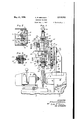
May 31, 1938. A. R. SPICACCI GRINDING MACHINE Filed Aug. 1, 1935 6 Sheets-Sheet 1 I K W c 0 nww M5 0, mo w 0 Z T T U 0. vv. 8
May 31, 1938. A. R. SPICACCI GRINDING MACHINE Filed Aug. 1, 1955 6 Sheets-Sheet 2 wi i a N R w T H w H May 31, 1938.
A68 I M2 1 i t i /38 A. R. SPICACCI GRINDING MACHINE Filed Aug. 1, 1935 6 Sheets-Sheet 5 INVENTOR. fiTTiMG R. spl cmcl, BY 4% Hi5 @Tmm/EY May 31, 1938. A. R. SPICACCI I GRINDING MACHINE Filed Aug. 1, 1935 6 Sheets-Sheet 4 m N .C w W m mo amw w m mfi w m H L EM mid Y 8 May 31, 1938. A. R. sP|cAcc| GRINDING MACHINE Filed Aug. 1, 1935 6 Sheets-Sheet 5 F113". ll
.Jm/I pvt m m fm Wm M R0 5 m H L T w? Y B atented ay 31, 1938 UNITED, STATES- PATENT OFFICE GRINDING MACHINE Attilio R. Spicacci, Bristol, Conn, assignor to General Motors Corporation, Detroit, Mich, a corporation of Delaware Application August 1,
31 Claims.
the invention is illustrated in connection with the formation of elliptical race curvatures for race rings of antiiriction bearings.
In the usual ball bearing, the raceway grooves are transversely arcuate and have a radius of curvature which is slightly larger than the radii of the balls. These raceways are usually produced on an oscillating grinding machine in which either the work or a grinding wheel is oscillated around a center. It has been found that certain raceway curvatures which are not circularly arcuate have certain advantages in respect to load capacity and endurance when applied to ball bearings, especially elliptical race- Ways wherein the curvature is defined by that part of an ellipse adjacent one end of the major axis. Accuracy of curvature is very important to get the desired advantages, and a departure of even one ten-thousandth part of an inch from the desired curve is'too large an error to be allowable.
An object of the invention, accordingly, is to provide a machine to generate accurately a noncircular curve, especially an elliptical curve. Another object is to produce a predetermined curve on a work-piece without the use of prepared templates and yet to create that curve by simple mechanism and motions which can be accurately its broader aspects, the invention is not necessarily limited to the specific constructions selected for illustrative purposes in the accompanying drawings in which Fig. 1 is a front elevation of 'a grinding machine.
Fig. 2 is a sectional View on the line 22 of Fig. l but showing some parts broken away at a lower level.
Fig. 3 is a sectional view on the line 3-3 Fig. l.
. axis.
1935, Serial No. 34,148
chine.
Fig. 4A is a front view of a slide. Fig. 5 is a view of portions of Fig. 4 enlarged.
Fig. 6 is a sectional view on line 6-6 of Fig. 5.
Fig. 7 is chiefly a vertical sectional view on the line 'l-l of Fig. 4.
Figs. 8 and 9 are diagrams.
Fig. 10 is a front elevation, partly broken away and in section, of a grinding machine of modified construction but utilizing the same basic principles of curve generation as in .the preceding figures.
Fig. 11 is a side elevation of Fig. 10.
Fig. 12 is a section on the line l2-l2 of Fig. 10.
Fig. 13 is a section on the line Ill-l3 of Fig. 11.
Fig. 14 is a section on the line i l-l4 of Fig. 11.
Figs. 15, 16 and 17 are diagrams.
In generating an elliptical curve, this invention utilizes the principle that a particle travel-' ling around the axis of a right cylinder in the surface thereof and also in an inclined plane will generate an ellipse. The minor axis of the ellipse is then the diameter of the cylinder and the major axis depends on the inclination. The ellipse can be varied to suit the particular bearing by changing the inclination or the diameter or both. Inasmuch as the desired curve is rather small in practice, actual movementof the generating member is controlled by rigidly connected and accurately mounted parts one of which moves in an amplified and hence accurately controlled ellipse which has a known relation to the desired elliptical path of the generating member.
The curvature'may be directly generated upon the race ring or work itself or maybe generated upon an abrading member which transfers the curve to the work.
In Fig. 8, the line A represents the axis of a cylinder, and a generating member D moves around such axis in' an inclined plane represented by the line K having the inclination T which can be selected. Referring to the triangle having sides K, P and r, the generating point moves angularly or oscillates at aselect'ed distance r from the axis while also having a selected vertical travel of an amplitude represented by the line P. The ellipse generated is indicated by the broken line e shown as 90 'out of its proper plane, such ellipse becoming more nearly circular if the inclination of K is decreased so that the distance K which is the semi-major axis approaches the distance T which is the semi-minor inasmuch as the distances. 7 and P are Fig. 4 is a side elevation of the grinding masmall (though exaggerated. in the diagram), con
trol of the path of the generating member is effected by certain rigidly connected members of rugged construction whose path is of related but more ample dimensions. A cam roller 18 travels on a cam represented as an inclined plane H having a selected inclination B. The line R represents the distance of the roller contact point from the axis A, and the roller has a vertical travel represented by line P, the roller imparting the same vertical travel to the connected member D. The contact point of the roller with the cam also travels in an ellipse E which is more nearly circular than the desired ellipse e but has a predetermined and computable: relation to the latter. The generating member or point D may be a diamond for producing a-transverse elliptical 'curve on a grinding wheel which transfers the shape to a work-piece.
In Figs. 1 and 4, the numeral 2 indicates a frame supportingv a work head 4 which may have any suitable chuck to hold and rotate a workpiece W (indicated by broken lines in Fig. 4) in contact with a grinding wheell The grinding wheel 6 is rotatably supported by a head 8 having a cross feed slide I8 controlled by a hand wheel/I2. Bolted to the rear of the head 8 is an upright bracket I4 whose upper end is provided with arcuate slots I6 for clamping screws I8 which adjustably secure a circular flange28 of an inclined slide base 22. The flange 28 has a centering plug 28 entering a circular recessin the bracket I4. The slide base has dovetail ways 24 one of which is provided with an adjustable gib 25 secured by screws 28. A dovetail tongue or slide 28 projects laterally into the ways from a circular flange 38 which is adjustably secured by clamping screws 82 to a circular flange 84 orf a carrier 36, the flange 34 having arcuate slots similar to the arcuate slots I8. The tongue or slide 28 has a nut 31 for a feed screw 88 which is journalled for rotation without endwise move ment in an end plate 48 fastened at the front ofand the slots I 6, a suitable scale 44 co-operating with an index line to show the angularity or inclination. A similar scale 48 on the flange 88, but graduated in the opposite direction, indicates the angular adjustment of the flange 84 and the parts carried by the carrier 88, such parts having a corrective angular adjustment to bring the gen-' erating member or diamond D back to the wheel periphery when moved away by adjustment of the inclination of the slide base.
The carrier 36 (see Fig. '7) has flanged bearing bushings 46 and 48 which support an upright shaft 58 for oscillation and vertical sliding. An arm 52 is fastened to the shaft by clamping screws 54, the arm being split as shown in Fig. 2 and having a vertical slot for a key 56 which enters a vertical keyway in the shaft, thus preventing relative rotation but providing for vertical adjustment of the arm on the shaft. To control a fine adjustment, the arm has a horizontal slot 68 receiving an eccentric 62 which can be turned on a supporting screw 64 projecting from the shaft. To control turning of the eccentric, the latter has a nut-like head 66. The clamping screws 54 are clination provided by pivot screws I6 extending into a lug I8 of the carrier 86, {The yoke has a wear plug 88 engaging the upperjend of a vertical adjusting screw 82 which is threaded in a web of the carrier 36. A lock nut 84 holds the screw 82 in adjusted position with the cam in the selected inclined plane H of Fig. 8. From the foregoing, it is apparent that, upon angular oscillation of the shaft 58 in its bearings, the cam and the cam roller will control vertical sliding of the shaft, the amplitude of vertical movement being determined by the inclination of the cam and the extent of angular oscillation of the arm 62. 1
The lower end of the shaft 88 has a squared enlargement 98 with slots for clamping screws 92 which adjustably anchor a detachable and replaceable bracket or arm 84 to the shaft. The slots provide for lateral adjustment of the bracket, the latter having a guide tongue 86 (Figs. 3 and 5) slidable in a groove of the enlargement 88. A pin 88 is driven into a hole of the bracket or arm 84 and has a flattened portion entering a slot in the enlargement. Vernier screws I88 are threaded in the enlargement in a position to abut against opposite sides of the flattened portion of the pin. A dial I82 is secured to each screw by a clamping screw I84. The foregoing mechanism provides for. accurate adjustment of the bracket or arm laterally so as to locate the generating member D in the plane of the center of the grinding wheel. The bracket or arm 84 has 'a rearwardly oflset and inclined extension I86 for a cone-ended stud 8' which supports the diamond D. The stud has a shank secured to a slidable pin II2 which is adjustable endwise in a guide openingof the extension. The pin has an annular notch II4 into which projects a collar II6 on an adjusting screw III which is threaded in a tapped opening I28 of the extension I88. A dial I22 is flxed to the adjuilting screw by a clamping screw I24. This adjustment provides for movement of the diamond D along a radius of the grinding wheel 8 and it also determines the distance of the diamond from the axis of oscillation. In other words, it determines the radius r or horizontal distance of the diamond from the axis A as'indicated in Fig. 8. This distance r is also one half the minor aids of the ellipse e because the point D is always in the surface of a cylinder having the radius r. The
' slide pin H2 is clamped in adjusted position by a clamping screw I26. I
The upper portion of the shaft 58 (see Fig. '1) is reduced in diameter to receive a sleeve I28 which is keyed from rotation on the shaft by a taper "pin I38. The sleeve has opposite pairs of elonbeing partly confined in a recess of a skirted housing I48 which is fastened to the carrier 36. The hub member is fastened by screws I to a worm Wheel I42 driven by a worm I44 on a shaft I46 which is journalled in lugs I48 on the carrier 86. The shaft I46 also carries a worm wheel I50 driven by a worm I52 keyed to a shaft I54 which is journalled in lugs I56 and I58 on the carrier 36. The shaft is turned by a crank I60'and this provides the power for giving the shaft and the diamond their oscillating and vertical shifting movements. The shaft and its larger arm 52 and its shorter arm 94 form a rugged unit which gives a compound movement to the diamond D without lost motion, the movement being compounded of oscillation around an axis A intersecting the grinding wheel parallel to the sides thereof and translation or linear movement parallel to said axis, said linear movement being controlled by and directly proportional to the angular movement in each direction.
Fixed by screws to the top of the housing I40 (see Figs. 1 and 4) is a. dial plate I62 having graduations co-operating with a pointer I64 fastened to the front of an arm I66 which is'keyed to the shaft 50 and secured by a screw I68. This device indicates the angle through which the shaft swings. The arm I66 will rise or fall with the shaft, its rear end being contained in a housing I10 which is fastened by screws I12 to the top of the housing I40. The housing I10 is open at the front to expose the dial and has an upright flange I14 to which an extension housing I16 is secured by a thumb screw I18. An opening at the top of. the extension housing receives a plug I which is carried by a cap I62 and fastened by a set screw I84. The cap has any suitable clamping means to hold a dial indicator I86 whose indicator stem I88 is slidable through the cap and plug to bear against a wear plug I90 in the top of the shaft 50. The indicator is used to determine the vertical movement of the shaft and enables the cam 12 to be set by the adjusting screw 82 at the proper inclination to give the desired vertical movement of the shaft for a given angular oscillation, the latter being determined by the dial I62. The adjustment afforded by the eccentric 62 when the clamping screws 54 are loosened gives a delicate adjustment of the shaft and diamond vertically up or down in order that the diamond may just touch the wheel in the central plane when the cam roller 10 is in its highest position on the cam.
In operation, the crank I60 is turned to swing the shaft 50 and the diamond or generating point D back and forth. The diamond must travel in an ellipse across the grinding wheel because, while oscillating around an axis, it is also caused to shift parallel'to that axis by the cam. A partial revolution of the shaft is sufficient to generate an elliptical contour on the grinding wheel. The previously described adjustments provide for varying the character of the ellipse.
Decreasing the inclination B of the cam 12 will obviously decrease the vertical travel P and the ellipse will more nearly approach a circle. This is equivalent to decreasing the distance K which is necessarily the'semi-major axis of the ellipse. The character of the ellipse can also be varied by adjusting the distance 1' which is always the semi-minor axis of the ellipse because it is the radius of a cylinder in the surface of which the point D moves while in the inclined plane K.
In Figs. 10 to 16, the curvature is generated directly upon the work W by causing a controlled relative shifting movement between the work and a grinding wheel and, in the selected embodiment, the work is shifted in an elliptical path while the wheel merely rotates on a fixed axis. A work head 202 is mounted on an upper slide 204 for longitudinal adjustment controlled by a feed screw 206. This adjustment will center the work with respect to the wheel. The upper slide is supported on a cross slide 208 adjustable by a feed screw 2I0 on a swingable supporting arm 2I2, the latter having an operating handle 2I3. The arm is connected to a vertical shaft 2M which is mounted to rotate and to slide vertically in suitable bearings offa casing 2I6 depending from a frame 2I8. The crosswise adjustment of the slide 208 will position the work at the desired distance from the shaft 2I4 and will thus determine the radius 1' of Fig. 15.
An arm 220 (corresponding to the arm 52 of Fig. 7) isfastened to the shaft M4 by clamping screws 222. A roller 224 is rotatably mounted in a slot of the arm 220 by a pivot stud 226 and runs on an arcuate cam plate 228 which is fastened by screws to a yoke 230. The yoke has its ends pivoted by pivot screws 232 to a bracket 234 fastened to the casing 2I6. A wear plug 236 on the yoke bears against the upper end of an adjusting screw 238 which is threaded in a lug 240 of the bracket 234. This adjustment provides for selecting the plane H or the angle of inclination B of the cam plate to give a predetermined rise and fall P to the work head as such work head is oscillated.
A grinding wheel 250 is rotatably mounted in a-head 252 carried by an inclined slide 254 having a dovetail slot fitting a dovetail guide tongue 256 (Fig. 13) on a supporting bar 258. The slide is shiftable by a feed screw 260 threaded in a nut 262 on the bar 258, the screw being journalled for rotation without endwise movement in a plate 264 bolted to the slide. The feed screw has a hand crank 266 and its operation will shift the grinding wheel radially with respect to the point where it engages the work-piece W and so compensate for wear or change in diameter of the wheel, The bar 258 is supported at its lower end by a pivot bolt 268 which is secured by caps 210 in bearing recesses of a slide 212. At the higher end, the bar has a projection 214 carrying a clamping bolt 216 which passes through arcuate slots 210 in lugs 280 ofa bracket 282. A nut 283 provides for clamping the projection 214 to the lugs with the bar 258 at aselected inclination which can be nicely determined by an adjusting screw 284. The setting determines the inclination of the plane K or the angle T. In order that the plane K may always pass through the centers of the wheel and the work the vertical location of the work can be varied, as by changing the position of the arm 220 on the shaft 2w by the clamping screws 222. The slide 212 has a dovetail slot guided on a dovetail tongue 286 of a support or table 288. A feed screw 290 is threaded in a nut 292 fastened to the support,
the screw being journalled for rotation without endwise movement in a plate 288 attached to the front of the slide. The screw has an operating hand wheel 296 and its operation adjusts the wheel with respect to the particular work. When the work is thus oscillated around an axis A with the accompanying rise and fall P, every point in the workpiece is caused to travel in an elliptical path and every point along the grooved raceway will come in contact with the operative edge 'is the same as if the operative point of the grinding wheel were moved in the same ellipse while the work is stationary or merely rotating on its axis. Hence the operative point of .the grinding wheel may be regarded as the generating point D because that point and the raceway have relative movement in an ellipse. Also a single selected point on the member W could be made to generate an ellipse on the grinding wheel since it has a motion directly comparable to the generating point D of Fig. 8.
In the preceding illustrated constructions, the ellipse is produced by giving just one of the engaging members a movement of both oscillation and translation. In Figs. 1 to 9, the diamond is given the two simultaneous movements and in Figs. to 16, the work is given these movements. As indicated diagrammatically in Fig.
,l'l, one of the engaging members may be given oscillating movement around an axis and simultaneously the-other member may be given the movement of translation. In this figure, the work W is oscillated around an axis A and the grinding wheel 250 is moved vertically, such vertical movement being controlled by an inclined cam 300 carried by an oscillating work support 302 and engaging a cam roller 304 on a vertically guided support 306 for the grinding wheel. Thus as compared with Fig. wherein the work is moved up and down, the grinding wheel is moved down and up as the work oscillates. Thus the two constantly engaging members have a relative movement which will generate an ellipse on the work although neither member alone moves in an elliptical path. In the foregoing constructions, the motions are exceedingly simple .and reliably controlled and the ellipse can be easily varied thus avoiding the expense of special templates to control the curvature.
I claim:
1. In a machine of the character described, a support for a grinding member, a support for a member having a point contact with the grinding member, means for oscillating one of said members around a fixed axis parallel to the sides of the grinding member to cause the point of contact to shift widthwise of one of the members, and means for causing said oscillated member to-have a linear movement in the plane of the grinding member during said oscillation; substantially as described.
2. In a machine of the character described, a support for a grinding member, a support for a member engaging the grinding member, means for giving the members a compound relative movement while in contact, said compound movement being composed of oscillation of one member around an axis intersecting the grinding member in a plane parallel to the sides thereof and linear translation of one member in a direction parallel to said axis of oscillation; substantially as described.
3. In a machine of the character described, a support for a grinding member, a support for a member engaging the grinding member, and means for giving said engaging member a compound movement while in contact with the grinding member, said compound movement being composed of oscillation around an axis intersecting the grinding member in a plane parallel to the sides thereof and linear movement parallel to said axis of oscillation; substantially as described.
4. In a machine of the character described, a support for a grinding wheel, a support for a member engaging the grinding wheel, means for oscillating said member around an axis to traverse it across the width of the grinding wheel, and means for shifting the member in the plane of the wheel as it oscillates across the wheel; substantially as described.
5. In a machine of the character described, a support for a grinding member, a support for a member engaging the grinding member, one of the supports comprising a shaft having rigid connection with one of the members, means for supporting the shaft for angular oscillation around an axis intersecting the grinding mem her in a plane parallel to the sides thereof, and means for causing the shaft to shift endwise as it oscillates; substantially as described.
-6. In a machine of the character described, a support for a grinding member, a support for a member engaging the grinding member, one of the supports comprising a shaft having rigid connections with one of the members, means for supporting the shaft for angular oscillation, and
means for causing the angular oscillation of the.
shaftto effect a. relative linear translation between the members, the linear translation being directly proportional to. the angular movement in each direction; substantially as described.
7. In a machine of the character described, a support for a grinding member, a support for a member engaging the grinding member, one of the supports comprising a shaft having connection with one of the members, means for supporting the shaft for angular oscillation, a cam, a cam follower, one of said last-named parts having connection with the shaft and the other part being relatively fixed whereby oscillation of the shaft causes it to shift endwise; substantially as described.
8. In a machine of the character described, a support for a grinding member, a support for a member engaging the grinding member, one of the supports comprising a shaft having connection with one of the members, means for supporting the shaft for angular oscillation on its axis, a cam, a cam follower, one of said lastnamed parts having connection with the shaft,
means for oscillating the shaft to cause the cam follower to traversethe cam and move the shaft along its axis, and means for changing the inclination of the cam; substantially as described.
9. In a machine of the character described, a
support for a, grinding member a support for a member engaging the grinding member, one of the supports comprising a shaft carrying one of the members, means for supporting the shaft for oscillation around its axis and for axial shifting, acam, a cam follower, one of said lastnamed parts being carried by the shaft, the cam presenting a surface inclined to the axis of the.
shaft, and a pivotal mounting for the cam to provide for varying its inclination; substantially as described.
10. In a machine of the character described, a support for a grinding wheel, a member engaging the grinding wheel, a shaft having rigid connec-- tion with one of said parts, means for supporting inclined to said axis, and means for causing relative movement between the wheel and the member'in said inclined plane; substantially as described.
12. In a machine of the character described, a support for a grinding wheel, a member engaging the grinding wheel, a shaft having rigid connection with one of said parts, means for sup-- porting the shaft for angular oscillation around its axis, said axis being fixed and arranged to intersect the wheel in a plane paralle to the sides of the wheel, and means to cause the shaft to shift axially on said fixed axis during said oscillation; substantially as described.
13. In a machine of the character described, a support for a grinding wheel, a support for a member engaging the grinding wheel, one of the 'tially as described.
14. In a machine of the character described, a support for a grinding wheel, a support for a member engaging the grinding wheel, one of the supports comprising an arm carrying the member, means for mounting the arm for angular oscillation around .a fixed axis to traverse the member across the width' of the wheel, and means for causing the arm to shift bodily in opposite directions lengthwise of said axis as a result of said oscillation; substantially as described.
15. ,In a machine of the character described, a support for a grinding wheel, a support for a member engaging the grinding wheel, one of the supports comprising a pair of connected arms of different length mounted to oscillate around an axis intersecting the grinding wheel, the member being carried by the shorter arm, and means cooperating with the longer arm for controlling movement of the member in a direction parallel to the axis of oscillation; substantially as described.
16. In a machine of the character described, a support for a grinding wheel, a support for a member engaging the grinding wheel, one of the supports'comprising a shaft, an arm mounted on the shaft and carrying the member, means for supporting the shaft for angular oscillation around its axis, and means for adjusting the arm and the member with respect to the shaft in a direction crosswise of the wheel to locate the member in the plane of the wheel; substantially as described.
17. In a machine of the character described, a
, support for a'grinding member, a support for a the supports comprising a shaft carrying one of the members, means for supporting the shaft for oscillation around its axis and for endwise shifting, a cam, a, cam follower, one of said last-.- named parts being carried by the shaft whereby oscillation of the shaft causes it to shift endwise, and means for indicating the amplitude of endwise shifting; substantially as described.
19. In a machine of the character described, a support for a grinding member, a support for a member engaging the grinding member, one of the supports comprising a shaft connected to one of said members, means for supporting the shaft for oscillation around a fixed axis, means for shifting the shaft lengthwise of its fixed axis and a slide for moving one of the members, said slide being inclined with respect to the shaft at an angle to produce relative movement of the members along a radius of the grinding member; substantially as described. A
20. In a machine of the character described, a support for a grinding wheel, a member engaging the grinding wheel, a shaft carrying the member, a carrier for supporting the shaft for oscillation around its axis, a slide for supporting the carrier, said slide being inclined with respect to the shaft at an angle to guide the member radially of the wheel, and means for shifting the slide at said angle; substantially as described.
21. In a machine of the character described, a support for a grinding wheel, a member engaging the grinding wheel, a shaft carrying the member, a carrier for supporting the shaft for oscillation around its axis, a slide for supporting the carrier, said slide being inclined with respect to the shaft at an angle to move the member radially of the wheel, and means for changing the inclination of the slide; substantially as described.
22. In a machine of the character described, a grinding wheel, a. member for supporting a workpiece in engagement with the grinding wheel, a shaft connected to the member, means for supporting the shaft for oscillation around its axis, a slide for supporting the grinding wheel, said slide being inclined with respect to the shaft at an angle to move the grinding wheel along that radius where it is engaged by the work-piece; substantially as described.
23. In a machine of the character described, a work head, a grinding wheel head, means for oscillating one of said heads around afixed axis parallel. to the sides of the grinding wheel, and
- means for causing relative movement of transallel to the sides of the grinding wheel, and 50 means for causing said oscillation to effect a relative movement of translation between said heads in opposite directions parallel to the axis of oscillation; substantially as described.
25. In a machine of the character described, a 5
work head, a grinding wheel head, means for oscillating one of said heads around an axis, a cam, a cam follower, and means for connecting one of said last-named members to the oscillating head whereby oscillation around an axis causes a relative movement of translation between the heads; substantially as described.
26. In a machine of the character described, a work-head having means to rotatably. support a work-piece, a grinding wheel, a head for rotatoscillating one of the heads around an axis with the work and wheel in contact, the wheel engaging the work on a radius which is inclined with respect to theaxis of oscillation, and means for eflecting relative movement between the workpiece and the wheel in the substantially as described.
27. In a machine or the character described, a work head having means to rotatably support a work-piece, a grinding member, a head for supporting the grinding member in contact with the work-piece, means for oscillating one of the heads around an axis, the grinding member enplane of the wheel;
gaging the work on a line which is inclined with tween the circular member and a generating member such that the point of engagement between the circular member and the generating member moves in a plane inclined to said established' axis while kept at a constant distance from said axis; substantially as described.
29. The method 01' generating an elliptical curve transversely across the periphery of a grinding wheel, whichco in establishing an 2,118,902 ably supporting the grinding wheel, means for axis in the plane of the grinding wheel, and moving a generating member across the periphery of the wheel in a plane inclined to said axis while maintaining the generating member at a constant distance from said axis; substantially as described 30. The method of grinding an elliptical curve transversely across the periphery of a circular work-piece which consists in establishing an axis in the plane of a grinding wheel, shifting said work-piece with respect to the grinding wheel in such manner that the point where the grinding wheel engages the work is maintained at a constant distance from said established axis and in a plane inclined to said axis; substantially as described.
31. The method of generating an elliptical surface of revolution on the periphery of a circular member which consists in establishing an axis of oscillation in a fixed location in the central plane 01' the circular member, rotating the circular member on its axis, and causing-said circular member and a contacting generating member to have relative shifting movement at their point 01' contact, the relative shitting movement being compounded of angular oscillation of one of the members around said fixed axis of oscillation, and straight line reciprocation of one of .the members in a direction parallel to said axis of oscillation and in proportion to the oscillation; substantially as described.
AT'I'ILIO R. SPICACCI.
Priority Applications (1)
| Application Number | Priority Date | Filing Date | Title |
|---|---|---|---|
| US34148A US2118902A (en) | 1935-08-01 | 1935-08-01 | Grinding machine |
Applications Claiming Priority (1)
| Application Number | Priority Date | Filing Date | Title |
|---|---|---|---|
| US34148A US2118902A (en) | 1935-08-01 | 1935-08-01 | Grinding machine |
Publications (1)
| Publication Number | Publication Date |
|---|---|
| US2118902A true US2118902A (en) | 1938-05-31 |
Family
ID=21874599
Family Applications (1)
| Application Number | Title | Priority Date | Filing Date |
|---|---|---|---|
| US34148A Expired - Lifetime US2118902A (en) | 1935-08-01 | 1935-08-01 | Grinding machine |
Country Status (1)
| Country | Link |
|---|---|
| US (1) | US2118902A (en) |
Cited By (4)
| Publication number | Priority date | Publication date | Assignee | Title |
|---|---|---|---|---|
| US2450742A (en) * | 1943-11-06 | 1948-10-05 | Gen Motors Corp | Lapping or polishing |
| US2453501A (en) * | 1944-04-03 | 1948-11-09 | Gear Grinding Mach Co | Trimming mechanism for grinder wheels |
| US2539506A (en) * | 1946-06-21 | 1951-01-30 | Norton Co | Grinding machine |
| US2583480A (en) * | 1948-05-15 | 1952-01-22 | Alfonse T Giglia | Radius and angle dresser |
-
1935
- 1935-08-01 US US34148A patent/US2118902A/en not_active Expired - Lifetime
Cited By (4)
| Publication number | Priority date | Publication date | Assignee | Title |
|---|---|---|---|---|
| US2450742A (en) * | 1943-11-06 | 1948-10-05 | Gen Motors Corp | Lapping or polishing |
| US2453501A (en) * | 1944-04-03 | 1948-11-09 | Gear Grinding Mach Co | Trimming mechanism for grinder wheels |
| US2539506A (en) * | 1946-06-21 | 1951-01-30 | Norton Co | Grinding machine |
| US2583480A (en) * | 1948-05-15 | 1952-01-22 | Alfonse T Giglia | Radius and angle dresser |
Similar Documents
| Publication | Publication Date | Title |
|---|---|---|
| US2747339A (en) | Lens grinding machine | |
| GB1450710A (en) | Machine for producing aspherical surfaces | |
| US2291000A (en) | Apparatus for producing multifocal lenses | |
| US2135202A (en) | Means for shaping the operative surfaces of grinding wheels | |
| US2836936A (en) | Apparatus for generating non-circular profiles and surfaces of revolution | |
| US2118902A (en) | Grinding machine | |
| US3289355A (en) | Automatic lens grinding machine | |
| US2401874A (en) | Grinding machine | |
| US2585973A (en) | Milling machine and method for impeller wheel manufacture | |
| US2932227A (en) | Machines for machining hollow bodies | |
| US1388039A (en) | Drill-grinder | |
| US467857A (en) | Universal tool-grinder | |
| US1897035A (en) | Grinding machine | |
| US2419529A (en) | Contour cutter grinder | |
| US2364322A (en) | Abrading machine | |
| US2396281A (en) | Machine tool | |
| US2231762A (en) | Grinding apparatus | |
| US2213756A (en) | Grinding machine | |
| US2429464A (en) | Lapping machine for generating diamond shapes | |
| US2384527A (en) | Machine tool | |
| US2442453A (en) | Grinding wheel dressing tool | |
| US2417413A (en) | Centerless grinding machine | |
| US1260022A (en) | Surfacing mechanism. | |
| US2932131A (en) | Tool grinder | |
| US2348881A (en) | Method of and apparatus for the |