US2102000A - Means for receiving delivered commodities and preventing theft thereof - Google Patents
Means for receiving delivered commodities and preventing theft thereof Download PDFInfo
- Publication number
- US2102000A US2102000A US92186A US9218636A US2102000A US 2102000 A US2102000 A US 2102000A US 92186 A US92186 A US 92186A US 9218636 A US9218636 A US 9218636A US 2102000 A US2102000 A US 2102000A
- Authority
- US
- United States
- Prior art keywords
- door
- receiver
- stop
- carrier
- street
- Prior art date
- Legal status (The legal status is an assumption and is not a legal conclusion. Google has not performed a legal analysis and makes no representation as to the accuracy of the status listed.)
- Expired - Lifetime
Links
Images
Classifications
-
- A—HUMAN NECESSITIES
- A47—FURNITURE; DOMESTIC ARTICLES OR APPLIANCES; COFFEE MILLS; SPICE MILLS; SUCTION CLEANERS IN GENERAL
- A47G—HOUSEHOLD OR TABLE EQUIPMENT
- A47G29/00—Supports, holders, or containers for household use, not provided for in groups A47G1/00-A47G27/00 or A47G33/00
- A47G29/14—Deposit receptacles for food, e.g. breakfast, milk, or large parcels; Similar receptacles for food or large parcels with appliances for preventing unauthorised removal of the deposited articles, i.e. food or large parcels
- A47G29/20—Deposit receptacles for food, e.g. breakfast, milk, or large parcels; Similar receptacles for food or large parcels with appliances for preventing unauthorised removal of the deposited articles, i.e. food or large parcels with appliances for preventing unauthorised removal of the deposited articles
- A47G29/22—Deposit receptacles for food, e.g. breakfast, milk, or large parcels; Similar receptacles for food or large parcels with appliances for preventing unauthorised removal of the deposited articles, i.e. food or large parcels with appliances for preventing unauthorised removal of the deposited articles having rotatable or reciprocable parts
Definitions
- This invention relates to a means for receiving delivered commodities and preventing theft thereof and provides an apparatus for attachment to doors such as street doors and adapted to receive goods such as a bottle of milk thereinjsaid apparatus being capable of manipulation so that when the street door is closed, said bottle or goods cannot be removed from the receiver, nor can the saidreceiver be moved into a position such as to allow of this, but when the door is opened, said receiver and bottle or goods therein, can be readfly and bodily removed from the door.
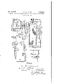
- Figure 1 is a sectional plan view illustrative of an embodiment of the invention, showing the container in the position it occupies, in relation to the street door, and adjacent jamb, when carrying a bottle of milk.
- Figure 2 is a vertical elevational view thereof.
- Figure 3 isa vertical elevation of a modification concerning a T shaped base member and catch piece hereinafter referred to.
- Figure 4 isa fragmentary perspective view of the upper end of a carrier bar showing a modified form of catch piece hereinafter described.
- Figure 5 is L a perspective viewof a modified form of carrier bar
- Figure 6 is a diagrammatic plan view of a further modification.
- a receiver 'I' of D-like formation constituted byupper andlower horizontally disposed D-shaped plates 2 con-- nected together by uprights 3 and wire mesh or expanded metal or a metal plate bent to required shape, and a receiver door constituted by a framing fitted with a wire mesh or other panel, said receiver door 4 being hingedly connected to the left hand upright 3 of the receiver and normally maintained closed by a spring 5.
- the carrier member consists of a fiat, rectangular section strip 6 which is bent to U shape ber I0 being preferably but not necessarily, formed of strip metal bent to provide flanges I I.
- the T-member I0 is adapted to engage over a T-shaped base member I2 provided with flanges I3 having screw-receiving holes therein, and said 'T-member I2 is secured to the front face of the street door I4 by means of screws I5 passed through the screw holes I aforesaid.
- the receiver I is, by its upper plate 2, rotatably mounted on the lower end of the spindle I6 and is supported on and rotatable on the upper face of a ratchet wheel I8 fixedly mounted on the lower end'of the spindle I6, whilst the lower plate 2 of the receiver I is provided on its underside with a socket or cup I9 rotatable on the pivotpin I! of the lower arm 8 of the carrier member, andwith said ratchet wheel I8 engage pawls 20 which are spring-controlled and piv-. otally mounted on the underside of the upper plate 2 of the receiver I.
- a spring-controlled stop piece H is .pivotally connected to the arched portion 9 of the carrier member, said stop piece 2I having a ball 22 disposed at right angles thereto. 7
- the T-slotted member II) of the carrier is slipped over the T- headed base member I2 on the street door I4, the stop piece 2I being held in raised position against the action of its spring, so that said member ID butts against a rib 23 on the end of the base member I2, and the flanges II of the member III cover over the screws I 5 which secure said member I2 to the street door I4, thereby preventing the device from being bodily removed, and the receiver I is turned anti-clockwise direction, so that the receiver door 4 faces, as shown by dotand-dash lines in Figure 1, outwardly from the street door I4 which is then closed.
- the receiver I After insertion of a bottle or other commodity I into the receiver I through the door thereof, said In this position the receiver I cannot be moved in a clockwise direction due to the pawls 2
- the device After opening the street door, the device is bodily slid off the T-headed base member l2, the bottle or the like is then removed from the receiver, and the stop piece 2
- the upper flange l3 of the T-shaped base member I2 is upwardly extended to pass beneath the movable stop Zl and prevent said stop bedding into and damaging the door.
- an abutment 21 to prevent the stop 2
- a spring 28, projecting laterally, bears on the top edge of the stop 2
- Figure 4 shows an alternative form of stop 2
- the device is mounted on the door jamb 24 and a fixed stop 33 is fitted on the door instead of providing a stop on the carrier bar. Opening of the door automatically retracts the stop 33 and allows the receiver to be turned to give access to the contents.
- a carrier having a detachable mounting on said base member such that it may be detached therefrom when the door is open and cannot be detached therefrom when the door is closed
- a goods receiver mounted on said carrier member for rotation relative thereto, in a single direction to two operative positions in one of which goods may be inserted therein and removed therefrom and in the other of which the insertion or removal of goods into or from the same is prevented by one of said elements, said goods receiver being movable from its first to its second mentioned position when the door is closed, means preventing reverse movement of said receiver, a releasable stop on said carrier to limit rotation of said receiver beyond its second mentioned position when the receiver is operat ively mounted on said base member, and means mounting said stop so that it isreleasable to permit rotation of the receiver from its sec-- and to its first mentioned position only when the carrier is detached from said base member.
Landscapes
- Engineering & Computer Science (AREA)
- Food Science & Technology (AREA)
- Supports Or Holders For Household Use (AREA)
Description
Dec. 14, 1937. G. F. R. HAYNES MEANS FOR RECEIVING DELIVERED COMMODITIES AND PREVENTING THEFT THEREOF Filed July 25, 1936 Patented Dec. '14, 1937 UNITED STATES 2,102,000 MEANS FOR RECEIVING DELIVERED COM- MODITIES AND PREVENTING THEREOF THEFT George Francis Richard Haynes London, England, assignor of one-half to Arthur Sutclifie,
London, England Application July 23, 1936, Serial No. 92,186 In Great Britain November 20, 1935 4 Claims. (01. 232-42) This invention relates to a means for receiving delivered commodities and preventing theft thereof and provides an apparatus for attachment to doors such as street doors and adapted to receive goods such as a bottle of milk thereinjsaid apparatus being capable of manipulation so that when the street door is closed, said bottle or goods cannot be removed from the receiver, nor can the saidreceiver be moved into a position such as to allow of this, but when the door is opened, said receiver and bottle or goods therein, can be readfly and bodily removed from the door.
For a readyunderstanding of the present invention reference is to be had to the following description and accompanying sheet of drawings,
wherein:--
Figure 1 is a sectional plan view illustrative of an embodiment of the invention, showing the container in the position it occupies, in relation to the street door, and adjacent jamb, when carrying a bottle of milk.
Figure 2 is a vertical elevational view thereof.
Figure 3 isa vertical elevation of a modification concerning a T shaped base member and catch piece hereinafter referred to.
Figure 4 isa fragmentary perspective view of the upper end of a carrier bar showing a modified form of catch piece hereinafter described.
Figure 5 is L a perspective viewof a modified form of carrier bar, and
Figure 6 is a diagrammatic plan view of a further modification.
Like numerals of referenceindicate corresponding parts in the said figures.
In carrying out the invention, and referring to the drawing, there is provided a receiver 'I' of D-like formation constituted byupper andlower horizontally disposed D-shaped plates 2 con-- nected together by uprights 3 and wire mesh or expanded metal or a metal plate bent to required shape, and a receiver door constituted by a framing fitted with a wire mesh or other panel, said receiver door 4 being hingedly connected to the left hand upright 3 of the receiver and normally maintained closed by a spring 5.
The carrier member consists of a fiat, rectangular section strip 6 which is bent to U shape ber I0 being preferably but not necessarily, formed of strip metal bent to provide flanges I I. The T-member I0 is adapted to engage over a T-shaped base member I2 provided with flanges I3 having screw-receiving holes therein, and said 'T-member I2 is secured to the front face of the street door I4 by means of screws I5 passed through the screw holes I aforesaid.
From the underside of and near to the outer end of the upper arm I of the carrier member there'fixedly depends a spindle I6 whilst on the upper sideof the lower arm 8 of the said carrier, there fixedly upstands a pivot pin I'I, said pin I'I; being in vertical alignment with the spindle I6 aforesaid.
The receiver I is, by its upper plate 2, rotatably mounted on the lower end of the spindle I6 and is supported on and rotatable on the upper face of a ratchet wheel I8 fixedly mounted on the lower end'of the spindle I6, whilst the lower plate 2 of the receiver I is provided on its underside with a socket or cup I9 rotatable on the pivotpin I! of the lower arm 8 of the carrier member, andwith said ratchet wheel I8 engage pawls 20 which are spring-controlled and piv-. otally mounted on the underside of the upper plate 2 of the receiver I.
A spring-controlled stop piece H is .pivotally connected to the arched portion 9 of the carrier member, said stop piece 2I having a ball 22 disposed at right angles thereto. 7
To set the device after removal, the T-slotted member II) of the carrier is slipped over the T- headed base member I2 on the street door I4, the stop piece 2I being held in raised position against the action of its spring, so that said member ID butts against a rib 23 on the end of the base member I2, and the flanges II of the member III cover over the screws I 5 which secure said member I2 to the street door I4, thereby preventing the device from being bodily removed, and the receiver I is turned anti-clockwise direction, so that the receiver door 4 faces, as shown by dotand-dash lines in Figure 1, outwardly from the street door I4 which is then closed.
After insertion of a bottle or other commodity I into the receiver I through the door thereof, said In this position the receiver I cannot be moved in a clockwise direction due to the pawls 2|] engaging the ratchet wheel IS, nor can said receiver I be moved in an anti-clockwise direction due to the stop piece 2| which is now inaccessible engaging the Wall of the receiver and the, face of the street door [4, and, further, the receiverdoor 4 cannot be opened sufiiciently wide as to allow of the extraction of the bottle 26 due to the free edge of the receiver door 4 contacting with the street door jamb 24, the interengaging members 10 and I2 of the device being positioned a distance away from the outer end of the street door I such that, whilst preventing the full opening of the receiver door 4 they allow of the receiver just clearing said jamb 24 when the door is opened.
After opening the street door, the device is bodily slid off the T-headed base member l2, the bottle or the like is then removed from the receiver, and the stop piece 2| is swung back beyond the position shown in dotted lines, allowing the receiver to be turned round so that the door of the receiver faces outwardly, whereupon the device is slid on to the T-head base member and the door then closed.
Although the invention has only been described and illustrated as applied to a street door which opens from right to left, yet the invention is equally well applicable to street doors which open from left to right, provided that the ratchet wheel and pawls' are arranged to suit the reverse turning of the bottle container. Further it is to be understood that the device in any of its forms herein described may be mounted on the jamb of the door instead of upon the door itself in which case it will be turned to face the door in order not to give access to its contents.
In the modification shownxin Figure 3 the upper flange l3 of the T-shaped base member I2 is upwardly extended to pass beneath the movable stop Zl and prevent said stop bedding into and damaging the door. There is also provided an abutment 21 to prevent the stop 2| being raised above the horizontal position so that in this case the stop has to be swung downwardly instead of upwardly to permit continued turning of the receiver after removal from the door. A spring 28, projecting laterally, bears on the top edge of the stop 2|, and temporarily maintains said stop raised to facilitate engaging the device on the door and will also retain it lowered during continued turning of the receiver when removed from the door.
Figure 4 shows an alternative form of stop 2| in the form of a sliding member, whilst in the modification shown in Figure a central doorengaging section 29 of the carrier is connected by co-axial pivots 30 to upper and lower sections 3|, 32 and therefore can be turned relative thereof when the device is removed from the door, to move the stop 2| which is now fixed and rigid with the section 29, to. a position in which it does not obstruct the container la In the modification shown in Figure 5 the device is mounted on the door jamb 24 and a fixed stop 33 is fitted on the door instead of providing a stop on the carrier bar. Opening of the door automatically retracts the stop 33 and allows the receiver to be turned to give access to the contents.
I claim:
1. In combination with a door element and a jamb, element, a base member fastened to one of said elements, a carrier having a detachable mounting on said base member such that it may be detached therefrom when the door is open and cannot be detached therefrom when the door is closed, a goods receiver mounted on said carrier member for rotation relative thereto, in a single direction to two operative positions in one of which goods may be inserted therein and removed therefrom and in the other of which the insertion or removal of goods into or from the same is prevented by one of said elements, said goods receiver being movable from its first to its second mentioned position when the door is closed, means preventing reverse movement of said receiver, a releasable stop on said carrier to limit rotation of said receiver beyond its second mentioned position when the receiver is operat ively mounted on said base member, and means mounting said stop so that it isreleasable to permit rotation of the receiver from its sec-- and to its first mentioned position only when the carrier is detached from said base member.
2,. The combination as set forth in claim 1 in which the stop is pivoted on the carrier and in which the base member is provided with a formation constituting an abutment to limit pivotal movement of the stop in one direction beyond a position in which it prevents rotation of the receiver when the carrier is mounted on the. base member, said stop being formed for cooperation with the receiver to prevent its pivotal movement in the other direction when the receiver is in its second mentioned position 3. The combination as set forth in claim 1 in which the carrier comprises at least two sections pivotally connected together, and in which the stop is rigid with one of said sections.
4. The combination as set forth in claim 1 in which the stop is slidably mounted on the carrier.
GEORGE. FRANCIS RICHARD HAYNES.
Applications Claiming Priority (1)
| Application Number | Priority Date | Filing Date | Title |
|---|---|---|---|
| GB2102000X | 1935-11-20 |
Publications (1)
| Publication Number | Publication Date |
|---|---|
| US2102000A true US2102000A (en) | 1937-12-14 |
Family
ID=10898507
Family Applications (1)
| Application Number | Title | Priority Date | Filing Date |
|---|---|---|---|
| US92186A Expired - Lifetime US2102000A (en) | 1935-11-20 | 1936-07-23 | Means for receiving delivered commodities and preventing theft thereof |
Country Status (1)
| Country | Link |
|---|---|
| US (1) | US2102000A (en) |
-
1936
- 1936-07-23 US US92186A patent/US2102000A/en not_active Expired - Lifetime
Similar Documents
| Publication | Publication Date | Title |
|---|---|---|
| US2643420A (en) | Door assembly and holder mechanism | |
| US2102000A (en) | Means for receiving delivered commodities and preventing theft thereof | |
| US2163356A (en) | Delivery shutter | |
| US2859913A (en) | Mail box flag | |
| US2479602A (en) | Window structure | |
| US2653043A (en) | Door closer | |
| US2834540A (en) | Door-opening attachment for ruraltype mailboxes | |
| US984101A (en) | Adjusting device for windows or doors. | |
| US2662253A (en) | Door for darkrooms | |
| US2592555A (en) | Door-actuated mailbox signal | |
| US1549422A (en) | Combined sash holder and sash release | |
| US1711282A (en) | Door holder | |
| US3224802A (en) | Door control apparatus | |
| US2924376A (en) | Mail box signal | |
| US3072322A (en) | Mailbox indicator | |
| US1955439A (en) | Overhead doorlock | |
| US2309407A (en) | Hold card holder | |
| US960817A (en) | Sash-hanger. | |
| US3212701A (en) | Mail box signal | |
| US3618262A (en) | By-passing door closer | |
| US1448135A (en) | Sliding-door fastener | |
| US2309604A (en) | Door holder | |
| US2708356A (en) | Control for garage door | |
| US2097802A (en) | Locking device | |
| US1710570A (en) | Stay or strut for hinged lids of gramophone and other cabinets |