US209010A - Improvement in breech-loading fire-arms - Google Patents
Improvement in breech-loading fire-arms Download PDFInfo
- Publication number
- US209010A US209010A US209010DA US209010A US 209010 A US209010 A US 209010A US 209010D A US209010D A US 209010DA US 209010 A US209010 A US 209010A
- Authority
- US
- United States
- Prior art keywords
- breech
- block
- arms
- shoulder
- brace
- Prior art date
- Legal status (The legal status is an assumption and is not a legal conclusion. Google has not performed a legal analysis and makes no representation as to the accuracy of the status listed.)
- Expired - Lifetime
Links
- 210000003811 finger Anatomy 0.000 description 3
- 244000309464 bull Species 0.000 description 2
- 238000010276 construction Methods 0.000 description 2
- 238000010304 firing Methods 0.000 description 2
- 230000037431 insertion Effects 0.000 description 2
- 238000003780 insertion Methods 0.000 description 2
- MFOUDYKPLGXPGO-UHFFFAOYSA-N propachlor Chemical compound ClCC(=O)N(C(C)C)C1=CC=CC=C1 MFOUDYKPLGXPGO-UHFFFAOYSA-N 0.000 description 2
- 231100000241 scar Toxicity 0.000 description 2
- 235000012571 Ficus glomerata Nutrition 0.000 description 1
- 240000000365 Ficus racemosa Species 0.000 description 1
- 235000015125 Sterculia urens Nutrition 0.000 description 1
- 238000005219 brazing Methods 0.000 description 1
- 150000001875 compounds Chemical class 0.000 description 1
- 210000005224 forefinger Anatomy 0.000 description 1
- 230000002452 interceptive effect Effects 0.000 description 1
- 230000000717 retained effect Effects 0.000 description 1
- 238000005728 strengthening Methods 0.000 description 1
- 210000003813 thumb Anatomy 0.000 description 1
Images

Classifications
-
- F—MECHANICAL ENGINEERING; LIGHTING; HEATING; WEAPONS; BLASTING
- F41—WEAPONS
- F41C—SMALLARMS, e.g. PISTOLS, RIFLES; ACCESSORIES THEREFOR
- F41C7/00—Shoulder-fired smallarms, e.g. rifles, carbines, shotguns
- F41C7/06—Lever-action guns, i.e. guns having a rocking lever for loading or cocking
-
- F—MECHANICAL ENGINEERING; LIGHTING; HEATING; WEAPONS; BLASTING
- F41—WEAPONS
- F41A—FUNCTIONAL FEATURES OR DETAILS COMMON TO BOTH SMALLARMS AND ORDNANCE, e.g. CANNONS; MOUNTINGS FOR SMALLARMS OR ORDNANCE
- F41A3/00—Breech mechanisms, e.g. locks
- F41A3/02—Block action, i.e. the main breech opening movement being transverse to the barrel axis
- F41A3/04—Block action, i.e. the main breech opening movement being transverse to the barrel axis with pivoting breech-block
Definitions
- My invention relates to that class of breechloading fire-arms in which the mechanism for opening and closing the rear end of the barrel for the insertion or removal of the cartridge or shell is arranged upon the principle adopted by M. Flobert,and set forth in a patent obtained by him November 17, 1855, No. 14,713, (Brevet dinvention, Tome 53, page 26, Plate 8, N. S.,) and incorporated in Letters Patent of the United States granted to me November 2, 1875, No. 169,413.
- My present improvements consist in simplifying, strengthening, and disposing the parts in such relative arrangement, together with such changes in construction, that the manual manipulation of the mechanism is greatly facilitated, and a more rapid and certain action obtained, with greater security against accident.
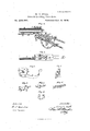
- Figure 1 represents a side elevation of that portion of thearm which includes the breech mechanism and other details embodyin g my improvements.
- Fig. 2 represents the same with the sideplate removed, showing the relative arrangement of the several operative parts in a closed position.
- Fig. 3 represents a similar view, with the operative parts in an open position.
- Fig. 4 is a vertical longitudinalcentral section;
- Fig. 5 a plan view and Figs. 6, 7, 8, 9, 10, 11 detached views, in perspective, of the breech mechanism.
- A is the barrel; B, the receiver, and U the stock.
- the barrel A and stockC are securely attached to the receiver in the usual manner, or in any desirable or well-known way.
- the receiver B is recessed to contain the breech nected to or made a part of the operating lever or guard F, and rotated upon trunnious f, which have their bearings arranged within the side plates or walls of the receiver B.
- a central mortise or slot, 0, and a conical aperture, 0 are formed in the breeehfblock, to all low the pivoted hammer G to operate therein, and to be raised independently of or with the opening movement of the breech-block.
- a shoulder, 0 is provided in the rear portion of the periphery of the breech-block to receive the pivoted locking-brace H, which secures the same when closed, and forms an abutment to resist its recoil action when the cartridge is exploded.
- breechblock E when opened, is in aposition beneath the line of the bore of the barrel, so that the cartridge may be readily inserted, and also ejected by the action of the extractor It, directly rearward, instead of being thrown upward toward the face of the operator, as in other guns of this class.
- the locking-brace H is swung upon trunnions h, and constructed with a concave side, that bears upon the corresponding convex surface of the breechblock, and is retained in contact therewith by the action of the spring t, and when the breech-block is closed it engages automatically with the shoulder 0
- the trigger K is pivoted at it within a slot in the locking-brace, as shown in Fig.
- a shoulder, Jr being formed in the latter, so that they move rigidly together with the forward movement of the trigger, which disengages the locking-brace from the shoulder 0 and in the rearward movement of the trigger, which acts to release the sear L from the tumbler g, in the usual manner, the locking-brace is not affected, except by a tendency to be pressed a aiust the shoulder c which insures the security of the breech-block at the instant of discharge.
- the hammer G is formed in one piece with the tumbler and is constructed with a coni- 2 aoaoro cal nose, g, fitted to enter the aperture 0 in the breech-block, and prevent the escape of gas or other matter therethrough when the cartridge is punctured and exploded, as described in my patent of November 2, 1875.
- the tumbler g is formed upon the lower portion of the hammer, and provided with the usual full-cock notch g while the half-cock notch is constructed in the form of an angular hook, as shown at g, Fig. 8, the point I, Fig. 9, of the sear L being formed to fit and engage therewith.
- the object of this construction is to arrest the hammer at the half-cock notch in the event of the sear becoming disengaged from the full-cock notch by accident, which is liable to occur when set with a haiutrigger!
- the scar L is pivoted at I, and extended rearward to engage with the spring i, which retains it in contact with the tumbler g and in position to be acted upon by the'trigger K for disengaging it.
- the pivot h being arranged in a line with the desired position of the sear, the latter is formed to encircle and pass by the same without interfering with the vertical movement of the sear.
- the extractor B Fig. .11, is pivoted at -r to the side plate, D, and arranged to en gage with the flange of the cartridge when in the- ,position shown in Fig. 2.
- the breech-block is reeessed about equal in depth to the thickness of the extractor,and the sides of this recess,
- 0 are formed in the proper radial lines, to act upon the extractor and cause it to move rearward when the breech-block has opened a sufiieient distance, and to return to its first position-when a new cartridge is inserted and the breech-block closed.
- the forward side of the extractor is constructed with an an gular projection, 1", which is acted upon by the shoulder 0 Figs. 2 and 6'. which imparts a quick movement to the extractor, and projects the cartridge entirely clear of the arm.
- the mainsprin g m is arranged beneath the barrel by means of the screw m, the free end of the spring acting within a concavity in the hammer formed below its center of motion, as shown in Fig. 1.
- the screw m is constructed with a conical head, as shown, which is provided with an aperture to allow the ramrod M to pass through. This aperture may be threaded to engage with a corresponding thread upon the ramrod and serve to retain it in its socket.
- the rear sight, N which 1 have devised and applied to this arm, is attached by means of two cheek-pieces, a a, secured by brazing, or otherwise, to the top of the barrel, through which and the sight-leaf an adjusting-screw, it, passes, which also serves as a pivot.
- the sight-leaf is constructed somewhat narrower than the space between the said cheek-pieces, to provide for a lateral adjustment, that may be desirable to allow for the efiect of the wind.
- the cheek-pieces n n are downwardly inclined toward the muzzle of the barrel, and serve to elevate and form a rest for the sight-leaf at short ranges by sliding the cross-bar a thereon. For long ranges the sight-leaf is elevated and the cross-bar a" raised or lowered, in the usual manner.
- the spring I is formed in one piece and with prongs i, the two former, it, acting upon the locking-brace H, and the latter or intermediate prong, t7, acting upon the rear end of the sear L, to retain them in their proper position.
- the tension of the intermediate prong, i may be varied by means of the adjustingscrew S when it is desired to diminish the force of the pulling action required in operating the trigger in firing.
- the manual manipulation of this mechanism is as follows: The neck of the stock (3 is grasped in the usual manner by the right hand, with the thumb over the top of the same, the forefinger forward of the trigger, the second finger behind it, (both within the lever or guard F,) and the remaining fingers beneath the lever or guard. The trigger is then pressed slightly forward by the second finger, which releases the locking-brace H from the shoulder a in the breech-block E, and at the same time the lever or guard is pressed downward, thereby opening the breech-block, which acts upon the extractor R, and ejects the eartridge from the barrel and raises the hammer to a full-cock.
- This action is efl'ected by a single movement of the hand and without changing its position, and may be simultaneous with the handling of the gun when lowerin g it from the shoulder to the hip immediately following a'discharge. This movement places the hand and gun in close proximity to the.
- the half-cock notch 9 constructed of an angular hooked form, substantially as shown,
Landscapes
- Engineering & Computer Science (AREA)
- General Engineering & Computer Science (AREA)
- Percussive Tools And Related Accessories (AREA)
Description
2 Sheets-Sheet 1, H. O. BULL; Breech-Loading Fire-Arm.
No. 209,010. Patented Oct. 15,1878.
2 Sheets-Sheet 2.
Breech-Loading Fire-Arm.
No. 209,010. I Patented Oct. 15,1878.
.Wz'l'n assw I In venZZr fiafazwa E SAM/mam UNITED STATES PATENT OEETE.
HENRY C. BULL, OF BROOKLYN, NEY" YORK.
IMPROVEMENT IN BREECH-LOADlNG FIRE-ARMS.
Specilication-forming part of Letters Pntcnth'o. 209,010. dated Qctober15, 187S; application filed August 5, 1876.
To all whom it may concern: 2
Be it known that I, HENRY (J. BULL, of the city of Brooklyn, county of Kings and State of New York, have invented certain new and useful Improvements in BreeclvLoading Fire- Arms; and I do hereby declare that the following is a full, clear, and exact description thereof, reference being had to the accompanying drawings, forming a part of this specification,and to the figures and letters marked thereon.
My invention relates to that class of breechloading fire-arms in which the mechanism for opening and closing the rear end of the barrel for the insertion or removal of the cartridge or shell is arranged upon the principle adopted by M. Flobert,and set forth in a patent obtained by him November 17, 1855, No. 14,713, (Brevet dinvention, Tome 53, page 26, Plate 8, N. S.,) and incorporated in Letters Patent of the United States granted to me November 2, 1875, No. 169,413.
My present improvements consist in simplifying, strengthening, and disposing the parts in such relative arrangement, together with such changes in construction, that the manual manipulation of the mechanism is greatly facilitated, and a more rapid and certain action obtained, with greater security against accident.
In the accompanying drawings, Figure 1 represents a side elevation of that portion of thearm which includes the breech mechanism and other details embodyin g my improvements. Fig. 2 represents the same with the sideplate removed, showing the relative arrangement of the several operative parts in a closed position. Fig. 3 represents a similar view, with the operative parts in an open position. Fig. 4 is a vertical longitudinalcentral section; Fig. 5 a plan view and Figs. 6, 7, 8, 9, 10, 11 detached views, in perspective, of the breech mechanism.
Similar letters of reference indicate corresporidin g parts in the several figures.
A is the barrel; B, the receiver, and U the stock. The barrel A and stockC are securely attached to the receiver in the usual manner, or in any desirable or well-known way. The receiver B is recessed to contain the breech nected to or made a part of the operating lever or guard F, and rotated upon trunnious f, which have their bearings arranged within the side plates or walls of the receiver B.
A central mortise or slot, 0, and a conical aperture, 0 are formed in the breeehfblock, to all low the pivoted hammer G to operate therein, and to be raised independently of or with the opening movement of the breech-block. A shoulder, 0 is provided in the rear portion of the periphery of the breech-block to receive the pivoted locking-brace H, which secures the same when closed, and forms an abutment to resist its recoil action when the cartridge is exploded.
It will be observed, Fig. 3, that the breechblock E, when opened, is in aposition beneath the line of the bore of the barrel, so that the cartridge may be readily inserted, and also ejected by the action of the extractor It, directly rearward, instead of being thrown upward toward the face of the operator, as in other guns of this class.
The locking-brace H is swung upon trunnions h, and constructed with a concave side, that bears upon the corresponding convex surface of the breechblock, and is retained in contact therewith by the action of the spring t, and when the breech-block is closed it engages automatically with the shoulder 0 The trigger K is pivoted at it within a slot in the locking-brace, as shown in Fig. 7, a shoulder, Jr, being formed in the latter, so that they move rigidly together with the forward movement of the trigger, which disengages the locking-brace from the shoulder 0 and in the rearward movement of the trigger, which acts to release the sear L from the tumbler g, in the usual manner, the locking-brace is not affected, except by a tendency to be pressed a aiust the shoulder c which insures the security of the breech-block at the instant of discharge.
The hammer G is formed in one piece with the tumbler and is constructed with a coni- 2 aoaoro cal nose, g, fitted to enter the aperture 0 in the breech-block, and prevent the escape of gas or other matter therethrough when the cartridge is punctured and exploded, as described in my patent of November 2, 1875.
The tumbler g is formed upon the lower portion of the hammer, and provided with the usual full-cock notch g while the half-cock notch is constructed in the form of an angular hook, as shown at g, Fig. 8, the point I, Fig. 9, of the sear L being formed to fit and engage therewith.
The object of this construction is to arrest the hammer at the half-cock notch in the event of the sear becoming disengaged from the full-cock notch by accident, which is liable to occur when set with a haiutrigger! The scar L is pivoted at I, and extended rearward to engage with the spring i, which retains it in contact with the tumbler g and in position to be acted upon by the'trigger K for disengaging it. The pivot h being arranged in a line with the desired position of the sear, the latter is formed to encircle and pass by the same without interfering with the vertical movement of the sear.
The extractor B, Fig. .11, is pivoted at -r to the side plate, D, and arranged to en gage with the flange of the cartridge when in the- ,position shown in Fig. 2. The breech-block is reeessed about equal in depth to the thickness of the extractor,and the sides of this recess,
0 are formed in the proper radial lines, to act upon the extractor and cause it to move rearward when the breech-block has opened a sufiieient distance, and to return to its first position-when a new cartridge is inserted and the breech-block closed. The forward side of the extractor is constructed with an an gular projection, 1", which is acted upon by the shoulder 0 Figs. 2 and 6'. which imparts a quick movement to the extractor, and projects the cartridge entirely clear of the arm.
The mainsprin g m is arranged beneath the barrel by means of the screw m, the free end of the spring acting within a concavity in the hammer formed below its center of motion, as shown in Fig. 1. The screw m is constructed with a conical head, as shown, which is provided with an aperture to allow the ramrod M to pass through. This aperture may be threaded to engage with a corresponding thread upon the ramrod and serve to retain it in its socket.
The rear sight, N, which 1 have devised and applied to this arm, is attached by means of two cheek-pieces, a a, secured by brazing, or otherwise, to the top of the barrel, through which and the sight-leaf an adjusting-screw, it, passes, which also serves as a pivot. The sight-leaf is constructed somewhat narrower than the space between the said cheek-pieces, to provide for a lateral adjustment, that may be desirable to allow for the efiect of the wind. The cheek-pieces n n are downwardly inclined toward the muzzle of the barrel, and serve to elevate and form a rest for the sight-leaf at short ranges by sliding the cross-bar a thereon. For long ranges the sight-leaf is elevated and the cross-bar a" raised or lowered, in the usual manner.
The spring I is formed in one piece and with prongs i, the two former, it, acting upon the locking-brace H, and the latter or intermediate prong, t7, acting upon the rear end of the sear L, to retain them in their proper position. v
The tension of the intermediate prong, i, may be varied by means of the adjustingscrew S when it is desired to diminish the force of the pulling action required in operating the trigger in firing.
The manual manipulation of this mechanism is as follows: The neck of the stock (3 is grasped in the usual manner by the right hand, with the thumb over the top of the same, the forefinger forward of the trigger, the second finger behind it, (both within the lever or guard F,) and the remaining fingers beneath the lever or guard. The trigger is then pressed slightly forward by the second finger, which releases the locking-brace H from the shoulder a in the breech-block E, and at the same time the lever or guard is pressed downward, thereby opening the breech-block, which acts upon the extractor R, and ejects the eartridge from the barrel and raises the hammer to a full-cock. This action is efl'ected by a single movement of the hand and without changing its position, and may be simultaneous with the handling of the gun when lowerin g it from the shoulder to the hip immediately following a'discharge. This movement places the hand and gun in close proximity to the.
cartridge box or belt, and during the insertion of a new cartridge a return movement of the.
hand, simultaneous with the act of bringing the arm to the shoulder, draws the lever up, which closes and locks the breech-block, leaving the hammer cocked ready for firing.
Having thus described my invention, I claim as new and desire to secure by Letters Patent- 1. The extractor R, pivoted within the receiver B, and constructed with an angular projection, 1", in combination with the rotating breech-block E, provided with arecess, c", inclosing and operating the extractor, substantially in the manner set forth.
2. The half-cock notch 9 constructed of an angular hooked form, substantially as shown,
in combination with the sear L, provided with the angular notch 1 as and for the purpose specified.
8. The pivoted locking-brace H, provided with a central slot or mortise and shoulder, k, in combination with the trigger K, pivoted within said slot, vibrating independently when operated to release the scar, and in connection with the locking brace when operating to diseug'a'ge the same from the shoulder a of I In testimouywhereof I have signed my namethe breech-block, as set forth. to this specification in the presence of two sub- 4. The combination of the compound spring scribing witnesses.
I by its two outside members with the lock- 7 1 iiig-brace H, so as to engage it ivith the breech- I HENRX B block E, andby its middle member with the Witnesses:
sear L, in the manner and for the purposes A. J .A. POLLOOK, substantially as described. v I ()OTAVE WHITTAKER.
Publications (1)
| Publication Number | Publication Date |
|---|---|
| US209010A true US209010A (en) | 1878-10-15 |
Family
ID=2278416
Family Applications (1)
| Application Number | Title | Priority Date | Filing Date |
|---|---|---|---|
| US209010D Expired - Lifetime US209010A (en) | Improvement in breech-loading fire-arms |
Country Status (1)
| Country | Link |
|---|---|
| US (1) | US209010A (en) |
-
0
- US US209010D patent/US209010A/en not_active Expired - Lifetime
Similar Documents
| Publication | Publication Date | Title |
|---|---|---|
| US520468A (en) | Revolver-lock mechanism | |
| US747585A (en) | Automatic firearm. | |
| US209010A (en) | Improvement in breech-loading fire-arms | |
| US621747A (en) | Gas-operated firearm | |
| US713254A (en) | Rifle. | |
| US202126A (en) | Improvement in breech-loading fire-arms | |
| US261648A (en) | Breech-loading fire-arm | |
| US772809A (en) | Single-trigger mechanism for double-barrel guns. | |
| US225423A (en) | Valentin saueebeey | |
| US136894A (en) | Improvement in breech-loading fire-arms | |
| US917723A (en) | Safety device for firearms. | |
| US49409A (en) | Improvement in magazine fire-arms | |
| US181301A (en) | Heney j | |
| US114653A (en) | Improvement in breech-loading fire-arms | |
| US827893A (en) | Breech-loading small-arm. | |
| US772746A (en) | Firearm. | |
| US46866A (en) | Improvement in breech-loading fire-arms | |
| US1021706A (en) | Firearm. | |
| US240653A (en) | Breech-loading fire-arm | |
| US160748A (en) | Ed wist buet | |
| US58525A (en) | Improvement in breech-loading fire-arms | |
| US220285A (en) | Improvement in breech-loading fire-arms | |
| US86566A (en) | Improvement in breech-loading- fire-arms | |
| US713874A (en) | Breech-loading cannon. | |
| US160919A (en) | Improvement in breech-loading flre-ar |