US2085563A - Fluid impregnated electric cable - Google Patents
Fluid impregnated electric cable Download PDFInfo
- Publication number
- US2085563A US2085563A US724000A US72400034A US2085563A US 2085563 A US2085563 A US 2085563A US 724000 A US724000 A US 724000A US 72400034 A US72400034 A US 72400034A US 2085563 A US2085563 A US 2085563A
- Authority
- US
- United States
- Prior art keywords
- sheath
- cable
- oil
- impregnated
- expansion
- Prior art date
- Legal status (The legal status is an assumption and is not a legal conclusion. Google has not performed a legal analysis and makes no representation as to the accuracy of the status listed.)
- Expired - Lifetime
Links
Images

Classifications
-
- H—ELECTRICITY
- H01—ELECTRIC ELEMENTS
- H01B—CABLES; CONDUCTORS; INSULATORS; SELECTION OF MATERIALS FOR THEIR CONDUCTIVE, INSULATING OR DIELECTRIC PROPERTIES
- H01B9/00—Power cables
- H01B9/06—Gas-pressure cables; Oil-pressure cables; Cables for use in conduits under fluid pressure
- H01B9/0611—Oil-pressure cables
Definitions
- This invention relates to cables having insulating wrappings impregnated with an insulating uid and sheathed with a metallic sheath. More particularly it ⁇ relates to a cable construction in which the cable or conductor is tightly wrapped with paper or similar fibrous wrapping which is impregnated with oil or other insulating fluidsandsheathed with a metallic sheath, and having means to maintain the wrapping impregnated at l0 all times with the insulating u'id.
- This invention relates particularly to the construction of the sheath and the method with which the'sheath is applied and the materials with which it is made and the means thereby for maintaining the cable insulation under complete impregnation at all times.
- the conductors in cables are subjected to varying amounts of electric current and are therefore subjected to heating effects which at times increase the temperature of the conductor and of its enclosing wrappings very considerablyand when the current decreases, permits this temperature to drop.
- the insulating wrappings'are thusheated the oil or insulating fluid expands.
- the sheath which expansion may be of the order of 1% to 3% of thev volume of the cable within the sheath.
- the pressure thus created within the sheath may be so great as to expand the sheath beyond the yield point of the lead and thus stretch it.
- the cable cools again the lead, being stretched, does' not return to its original size and therefore creates voids or empty spaces Within the cable under the sheath.
- the object oi the present invention is to provide a sheath comprised of metal of relatively high elasticity and to provide said sheath with means to permit the sheath to expand with the Within the sheath is reduced if not eliminated g5 and the life of the cable thereby extended beyond the life of ordinary oil impregnated cables no existing.
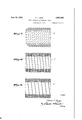
- Fig. 2 is a side 1 elevation partly in section showing the manner of applying the sheath of the present invention to the cable of Fig. l.
- Fig. 3 is a cross-section of a cable with a modiiied form of the sheath of the present invention.
- Fig. 4 is a side elevation partly in section of the cable of Fig. 3.
- Figs. 5, 6, '7, 8, 9 are cross-sections of the cable sheath showing various modifications of the sheath contemplated Within the scope of the pres-v ent invention.
- the conductor I is Within and surrounded by successive layers of paper wrapping 2 thereby providing a conductor having a suiiicient thickness of insulationbetween it and enclosing sheath 3 which may be of copper or other suitable material.
- sheath 3 is preferably a seamless copper tube drawn over the cable with the various lengths of the tube being joined vtogether to form a seal such as by threaded portions, one end fitting over the end of another and the two soldered together by means of a softsolder.
- annular space 4 Between the periphery of the cable core and the, inside of the sheath consisting of the tubing, there is an annular space 4 which permits of the cable being drawn into the tube.
- the cable is then impregnated by the usual means known to the art and which is usually referred to as oil-lled type of impregnation.
- Fig. 3 the conductor insulation 2 is surrounded by a metal or metallized shielding tape I2 of known construction and a series of wrappings of loosely taped paper 5 or similar mate' grounded at convenient intervals to the sheath.
- the paper 5 maybe made up with copper wire 5a stitched into it.
- the sheath After the sheath is jointed together it is crrugated as at l in Fig. 4. After the corrugating process, the sheath may be Wrapped loosely with v a Wire 9 i Fig. 4)- of copper or of the same materialas the sheath to assist the sheath in retaining its shape. Over the sheath 3 after it is corrugated may be appliedV two or more layers of paper tape I and over the tapes one ormore layers of reinforced rubber vll (Fig.- 4) which may be self-vulcanizing.
- Over the krubber Il may bel applied if desired, a braid i3 as the outside covering, the object of these wrappings over the sheath 3 being to provide a protectivecover over the sheath' to save it from deterioration from external causes. It will be understood that other forms of construction may be used for this purpose by varying the materials and methvods of application over the sheath 3.
- the principal object of this invention is to provide a means for permitting the expansion of the cable and of its contracting again to its original size to prevent ⁇ formation of voids.
- This is accomplished in the construction as shown in Figs. 1 and 2 by the pressure iormed"within the cable distorting the side Walls of the corrugated portions ofthe tubing 3 thus permitting a greater volume underneath the sheath.
- the sheath' is so constructed that 3 and 4 there are two kinds of expansion permitted, the principal one being the expansion made possible by the bulging of the plaited copper forming the sheath and the distortion of the corrugations the corrugations therein also permitting the cable to be bent and handled without injury.
- this cable is impregnated in the same manner as stated above after the sheath is applied.
- An oil impregnated cable comprising an electrical conductor, a wrapping of oil absorb ing material therearound, and an enclosing expansible and contractible sheath of copper having angular annular pleats overlapping yet clear-l ing one another to impart to the said sheath a relatively high flexibility.
- a sheath consisting of a plurality of united sections of seamless metal tubing of relatively high elasticity cora rugated helically and radially to render said tubing flexible andto provide means to expand and contract said sheath upon the expansion and contraction of materials contained lwithin said sheath.
- a tubular seamless sheath oi' plaited copper helically corrugated to render the said sheath flexible and to provide meansto expand and contract said sheath upon expansion and contraction of materials 'lcontained within said sheath.
- An oil impregnated cable comprising an electrical conductor surrounded by oil impregnated insulation, an enclosing tubular metal expansible and contractible sheath corrugated to impart relatively high flexibility thereto, the inner diameter measured across the inner portions of the corrugations of said sheath being substantially equal to the diameter of said impregnated insulation.
- An oil impregnated cable comprising an electrical conductor, a body of oil absorbing insulat- 165 being substantially or approximately equal to the outside diameter of said insulation.
- An oil impregnated cable comprising an electrical conductor, a body of oil absorbing material therearound, a corrugatedl expansible and contractible metallic sheath of relatively high elasticity, and a protective envelope enclosing such corrugated sheath.
- An oil impregnated cable comprising an electrical conductor, a wrapping of oil absorbing material therearound, a seamless metal tubing of relatively high elasticity corrugated both helically and radially to render said tubing exible and to provide means to expand and contract said sheath upon the expansion and contraction of materials contained within the sheath and a covering engaging and surrounding the exterior of said sheath.
Landscapes
- Insulated Conductors (AREA)
Description
June 29, 1937. F. L. AIME FLUID IMPEECNATED ELECTRIC CABLE 2 Sheets-Sheetv l Filed May 5, 1954 ttarncy June 29, 1937.
FLUI F. L. AIME D IMPREGNATED ELECTRIC CABLE Filed May 5, 1954 2 sheets-sheet 2 nvenrlor Patented June 29, 1937 UNITED STATES PATENT OFFICE Frank L. Aime, New York, N. Y., assignor to Anaconda Wire & Cable Company, New York, N. Y., a corporation of Delaware Application May'5, 1934, Serial No. 724,000
9 Claims.
This invention relates to cables having insulating wrappings impregnated with an insulating uid and sheathed with a metallic sheath. More particularly it `relates to a cable construction in which the cable or conductor is tightly wrapped with paper or similar fibrous wrapping which is impregnated with oil or other insulating fluidsandsheathed with a metallic sheath, and having means to maintain the wrapping impregnated at l0 all times with the insulating u'id. This invention relates particularly to the construction of the sheath and the method with which the'sheath is applied and the materials with which it is made and the means thereby for maintaining the cable insulation under complete impregnation at all times.
The conductors in cables are subjected to varying amounts of electric current and are therefore subjected to heating effects which at times increase the temperature of the conductor and of its enclosing wrappings very considerablyand when the current decreases, permits this temperature to drop. When the insulating wrappings'are thusheated, the oil or insulating fluid expands.
A considerable pressure is exerted Within the sheath of the cable due to the expansion of the l. impregnating uid and the expansion of the other materials making up the coreof the cable itself, such as copper and fibrous wrappings,
which expansion may be of the order of 1% to 3% of thev volume of the cable within the sheath. When the cable is covered with a lead sheath, the pressure thus created within the sheath may be so great as to expand the sheath beyond the yield point of the lead and thus stretch it. When the cable cools again the lead, being stretched, does' not return to its original size and therefore creates voids or empty spaces Within the cable under the sheath.
40 It is well known that the creation of such voids tends to ionization and thus produces deterioration of the cable insulation in a much shorter time than would be the case if those voids did not exist and the cable were operating normally.
The object oi the present invention is to provide a sheath comprised of metal of relatively high elasticity and to provide said sheath with means to permit the sheath to expand with the Within the sheath is reduced if not eliminated g5 and the life of the cable thereby extended beyond the life of ordinary oil impregnated cables no existing.
By the practice oi the present invention it is possible to use insulation thicknesses smaller than are usually used in solid type cables, and approaching or equalling those usually used in the so-called oil-filled type cables. Such decreased amount of insulation is successful only when the impregnation` of the insulating wrappings is maintained or nearly so during the service life thereof.
It Will be seenby those familiar with the art that the construction herein described provides a cable Whose characteristics are that oi the socalled oil-filled type, while it is constructed in a manner oi the solid type of cable. lit the same time it becomes unnecessary for the cable of this Fig. lis a cross-section of the cable and the enveloping sheath of one type. Fig. 2 is a side 1 elevation partly in section showing the manner of applying the sheath of the present invention to the cable of Fig. l. Fig. 3 is a cross-section of a cable with a modiiied form of the sheath of the present invention. Fig. 4 is a side elevation partly in section of the cable of Fig. 3.
Figs. 5, 6, '7, 8, 9 are cross-sections of the cable sheath showing various modifications of the sheath contemplated Within the scope of the pres-v ent invention.
In the embodiment shown in the accompanying drawings, the conductor I is Within and surrounded by successive layers of paper wrapping 2 thereby providing a conductor having a suiiicient thickness of insulationbetween it and enclosing sheath 3 which may be of copper or other suitable material.
In Fig. l the cable composed of the wrapped conductor is inserted in the sheath 3 which is formed in the shape shown in Fig. 2. Sheath 3 is preferably a seamless copper tube drawn over the cable with the various lengths of the tube being joined vtogether to form a seal such as by threaded portions, one end fitting over the end of another and the two soldered together by means of a softsolder. Between the periphery of the cable core and the, inside of the sheath consisting of the tubing, there is an annular space 4 which permits of the cable being drawn into the tube. After sufficient number of lengths of tubing are drawn over the cable and their ends joined together to' make an oil-tight sheath, the cable is then impregnated by the usual means known to the art and which is usually referred to as oil-lled type of impregnation.
In Fig. 3 the conductor insulation 2 is surrounded by a metal or metallized shielding tape I2 of known construction and a series of wrappings of loosely taped paper 5 or similar mate' grounded at convenient intervals to the sheath.
For this purpose the paper 5 maybe made up with copper wire 5a stitched into it.
After the sheath is jointed together it is crrugated as at l in Fig. 4. After the corrugating process, the sheath may be Wrapped loosely with v a Wire 9 i Fig. 4)- of copper or of the same materialas the sheath to assist the sheath in retaining its shape. Over the sheath 3 after it is corrugated may be appliedV two or more layers of paper tape I and over the tapes one ormore layers of reinforced rubber vll (Fig.- 4) which may be self-vulcanizing. Over the krubber Il may bel applied if desired, a braid i3 as the outside covering, the object of these wrappings over the sheath 3 being to provide a protectivecover over the sheath' to save it from deterioration from external causes. It will be understood that other forms of construction may be used for this purpose by varying the materials and methvods of application over the sheath 3.
It will Ybe understood that the principal object of this invention, particularly of the sheath con'- struction` shown herein is to provide a means for permitting the expansion of the cable and of its contracting again to its original size to prevent` formation of voids. This is accomplished in the construction as shown in Figs. 1 and 2 by the pressure iormed"within the cable distorting the side Walls of the corrugated portions ofthe tubing 3 thus permitting a greater volume underneath the sheath. The sheath' is so constructed that 3 and 4 there are two kinds of expansion permitted, the principal one being the expansion made possible by the bulging of the plaited copper forming the sheath and the distortion of the corrugations the corrugations therein also permitting the cable to be bent and handled without injury. Of course, it is understood in Figs. 3 and 4 that this cable is impregnated in the same manner as stated above after the sheath is applied.
In the modifications of sheath 3 illustrated in v Figs. 5 to 9 inclusive, I have shown different types of corrugations adaptedor use in the present invention, each of lwhich modifications may have peculiar advantages for use under certain service conditions.
Having broadly and specifically described the present invention, it is apparent that many modifications and departures may be made therein without departing essentially fr om the nature and scope thereof as may be included within the following claims.
What I claim is: 1. An oil impregnated cable comprising an electrical conductor, a wrapping of oil absorb ing material therearound, and an enclosing expansible and contractible sheath of copper having angular annular pleats overlapping yet clear-l ing one another to impart to the said sheath a relatively high flexibility.
Y2. In an oil impregnatedlcable, a sheath consisting of a plurality of united sections of seamless metal tubing of relatively high elasticity cora rugated helically and radially to render said tubing flexible andto provide means to expand and contract said sheath upon the expansion and contraction of materials contained lwithin said sheath.
3. In an oil impregnated cable, a tubular seamless sheath oi' plaited copper helically corrugated to render the said sheath flexible and to provide meansto expand and contract said sheath upon expansion and contraction of materials 'lcontained within said sheath.`
4.111 a fluid impregnated cable, a core of wrapped insulating material surrounded by a metal shielding tape grounded at convenient intervals to the sheath and a series of comparatively loosely applied iibrous wrappings over the shielding tape andsheathed in a seamless metal sheath having annular angular pleats which 4vrender said sheath flexible and to provide means to expand and contract said sheath upon expansion and contraction materials contained within said sheath. l
-5. In a uid impregnated cable, a core of wrapped insulating material surrounded by a metal shielding tape grounded at convenient intervals to the sheath and a series of comparatively loosely applied fibrous wrappings over the shielding tape and Asheathed in a copper sheath corrugated helically and radially torender said sheath flexible and toy provide means to' expand and contract said sheath upon expansion and contraction materials contained within said- 'sheath and a reinforcing element seated in the outer groove of thehelical corrugation.
6. An oil impregnated cable comprising an electrical conductor surrounded by oil impregnated insulation, an enclosing tubular metal expansible and contractible sheath corrugated to impart relatively high flexibility thereto, the inner diameter measured across the inner portions of the corrugations of said sheath being substantially equal to the diameter of said impregnated insulation.
7. An oil impregnated cable comprising an electrical conductor, a body of oil absorbing insulat- 165 being substantially or approximately equal to the outside diameter of said insulation.
8. An oil impregnated cable comprising an electrical conductor, a body of oil absorbing material therearound, a corrugatedl expansible and contractible metallic sheath of relatively high elasticity, and a protective envelope enclosing such corrugated sheath.
9. An oil impregnated cable comprising an electrical conductor, a wrapping of oil absorbing material therearound, a seamless metal tubing of relatively high elasticity corrugated both helically and radially to render said tubing exible and to provide means to expand and contract said sheath upon the expansion and contraction of materials contained within the sheath and a covering engaging and surrounding the exterior of said sheath.
FRANK L. AIME.
Priority Applications (1)
| Application Number | Priority Date | Filing Date | Title |
|---|---|---|---|
| US724000A US2085563A (en) | 1934-05-05 | 1934-05-05 | Fluid impregnated electric cable |
Applications Claiming Priority (1)
| Application Number | Priority Date | Filing Date | Title |
|---|---|---|---|
| US724000A US2085563A (en) | 1934-05-05 | 1934-05-05 | Fluid impregnated electric cable |
Publications (1)
| Publication Number | Publication Date |
|---|---|
| US2085563A true US2085563A (en) | 1937-06-29 |
Family
ID=24908543
Family Applications (1)
| Application Number | Title | Priority Date | Filing Date |
|---|---|---|---|
| US724000A Expired - Lifetime US2085563A (en) | 1934-05-05 | 1934-05-05 | Fluid impregnated electric cable |
Country Status (1)
| Country | Link |
|---|---|
| US (1) | US2085563A (en) |
Cited By (10)
| Publication number | Priority date | Publication date | Assignee | Title |
|---|---|---|---|---|
| US2508774A (en) * | 1945-06-15 | 1950-05-23 | Roberts Robert Eldon | Flexible tube |
| US2657364A (en) * | 1949-07-22 | 1953-10-27 | Airtron Inc | Pressure containing flexible wave guide |
| US2658939A (en) * | 1948-07-29 | 1953-11-10 | Anaconda Wire & Cable Co | Power cable containing fluid under pressure |
| US2696834A (en) * | 1949-05-11 | 1954-12-14 | Airtron Inc | Flexible wave guide |
| US2784989A (en) * | 1952-02-21 | 1957-03-12 | Goodrich Co B F | Flexible hollow connection |
| US2852216A (en) * | 1954-09-16 | 1958-09-16 | Melville F Peters | Refueling conduit |
| US2876801A (en) * | 1955-03-10 | 1959-03-10 | Breeze Corp | Metal convolution tubing |
| US4132264A (en) * | 1974-12-20 | 1979-01-02 | Ecodyne Corporation | Plastic heat exchange tube |
| US5317955A (en) * | 1990-08-10 | 1994-06-07 | Raser William H | Bellows with annular volume fillers |
| US20140290978A1 (en) * | 2011-12-20 | 2014-10-02 | Mitsubishi Electric Corporation | Insulation structure of lead wire, transformer having the same, and method for insulating lead wire |
-
1934
- 1934-05-05 US US724000A patent/US2085563A/en not_active Expired - Lifetime
Cited By (10)
| Publication number | Priority date | Publication date | Assignee | Title |
|---|---|---|---|---|
| US2508774A (en) * | 1945-06-15 | 1950-05-23 | Roberts Robert Eldon | Flexible tube |
| US2658939A (en) * | 1948-07-29 | 1953-11-10 | Anaconda Wire & Cable Co | Power cable containing fluid under pressure |
| US2696834A (en) * | 1949-05-11 | 1954-12-14 | Airtron Inc | Flexible wave guide |
| US2657364A (en) * | 1949-07-22 | 1953-10-27 | Airtron Inc | Pressure containing flexible wave guide |
| US2784989A (en) * | 1952-02-21 | 1957-03-12 | Goodrich Co B F | Flexible hollow connection |
| US2852216A (en) * | 1954-09-16 | 1958-09-16 | Melville F Peters | Refueling conduit |
| US2876801A (en) * | 1955-03-10 | 1959-03-10 | Breeze Corp | Metal convolution tubing |
| US4132264A (en) * | 1974-12-20 | 1979-01-02 | Ecodyne Corporation | Plastic heat exchange tube |
| US5317955A (en) * | 1990-08-10 | 1994-06-07 | Raser William H | Bellows with annular volume fillers |
| US20140290978A1 (en) * | 2011-12-20 | 2014-10-02 | Mitsubishi Electric Corporation | Insulation structure of lead wire, transformer having the same, and method for insulating lead wire |
Similar Documents
| Publication | Publication Date | Title |
|---|---|---|
| US2085563A (en) | Fluid impregnated electric cable | |
| US2847499A (en) | Coaxial cable | |
| US3051771A (en) | Electrostatic shield for high voltage cables | |
| US3843830A (en) | Electric cable with corrugated sheath and semi-conductive protective layer between the sheath and the core | |
| US1743506A (en) | Electric cable | |
| US2556187A (en) | Flexible waveguide with spaced conducting sections and method of making the same | |
| US2277177A (en) | Shield for electrical conductors | |
| US2866843A (en) | Corrugated compression type electric cables | |
| US3051770A (en) | Normal joint for high tension cables and process of making the same | |
| US2180420A (en) | Insulated spool for electromagnets | |
| US2041842A (en) | Electric cable and method of manufacturing it | |
| US2118584A (en) | Fluid impregnated electric cable | |
| US2282003A (en) | Electric cable | |
| US2271057A (en) | Retractile conductor cord and method of making such a cord | |
| US2189091A (en) | Flexible high frequency cable | |
| US2316558A (en) | Transformer | |
| US2050991A (en) | Cable and method of making | |
| US2149771A (en) | Electric cable | |
| US2406676A (en) | Cable joint | |
| US1988279A (en) | Terminal and joint for electric cables | |
| US2259850A (en) | Sheathed electric cable | |
| US2264439A (en) | Nonmetallic sheathed cable | |
| US2052922A (en) | Electric cable | |
| US2196026A (en) | Fluid filled cable | |
| US1757030A (en) | Electric cable |