US2082829A - Exercise apparatus - Google Patents
Exercise apparatus Download PDFInfo
- Publication number
- US2082829A US2082829A US50339A US5033935A US2082829A US 2082829 A US2082829 A US 2082829A US 50339 A US50339 A US 50339A US 5033935 A US5033935 A US 5033935A US 2082829 A US2082829 A US 2082829A
- Authority
- US
- United States
- Prior art keywords
- foot
- feet
- support
- user
- exercise apparatus
- Prior art date
- Legal status (The legal status is an assumption and is not a legal conclusion. Google has not performed a legal analysis and makes no representation as to the accuracy of the status listed.)
- Expired - Lifetime
Links
- 210000002683 foot Anatomy 0.000 description 25
- 210000003205 muscle Anatomy 0.000 description 4
- 238000005452 bending Methods 0.000 description 3
- 239000004744 fabric Substances 0.000 description 3
- 239000011435 rock Substances 0.000 description 3
- 210000003371 toe Anatomy 0.000 description 3
- 239000000463 material Substances 0.000 description 2
- 238000005096 rolling process Methods 0.000 description 2
- 238000010276 construction Methods 0.000 description 1
- 230000000694 effects Effects 0.000 description 1
- 239000002184 metal Substances 0.000 description 1
- 230000003387 muscular Effects 0.000 description 1
- 230000002787 reinforcement Effects 0.000 description 1
- 230000003014 reinforcing effect Effects 0.000 description 1
- 238000012559 user support system Methods 0.000 description 1
Images
Classifications
-
- A—HUMAN NECESSITIES
- A63—SPORTS; GAMES; AMUSEMENTS
- A63B—APPARATUS FOR PHYSICAL TRAINING, GYMNASTICS, SWIMMING, CLIMBING, OR FENCING; BALL GAMES; TRAINING EQUIPMENT
- A63B23/00—Exercising apparatus specially adapted for particular parts of the body
- A63B23/035—Exercising apparatus specially adapted for particular parts of the body for limbs, i.e. upper or lower limbs, e.g. simultaneously
- A63B23/04—Exercising apparatus specially adapted for particular parts of the body for limbs, i.e. upper or lower limbs, e.g. simultaneously for lower limbs
- A63B23/10—Exercising apparatus specially adapted for particular parts of the body for limbs, i.e. upper or lower limbs, e.g. simultaneously for lower limbs for feet or toes
-
- A—HUMAN NECESSITIES
- A61—MEDICAL OR VETERINARY SCIENCE; HYGIENE
- A61H—PHYSICAL THERAPY APPARATUS, e.g. DEVICES FOR LOCATING OR STIMULATING REFLEX POINTS IN THE BODY; ARTIFICIAL RESPIRATION; MASSAGE; BATHING DEVICES FOR SPECIAL THERAPEUTIC OR HYGIENIC PURPOSES OR SPECIFIC PARTS OF THE BODY
- A61H2201/00—Characteristics of apparatus not provided for in the preceding codes
- A61H2201/12—Driving means
- A61H2201/1253—Driving means driven by a human being, e.g. hand driven
- A61H2201/1261—Driving means driven by a human being, e.g. hand driven combined with active exercising of the patient
- A61H2201/1284—Driving means driven by a human being, e.g. hand driven combined with active exercising of the patient using own weight
Definitions
- Figure 4 is an end view
- Figure 5 is a transverse vertical section, taken at line 5 5 of Figure 3;
- Figure 6 illustrates a modified form of the device.
- the device comprises an exercising apparatus which may be supported upon a floor or any other foundation or base.
- the device is made of cast metal but it might be made of any other material and formed in any other way.
- I are end members having laterally extended feet portions 2, 2.
- the end members may be perforated as at 3.
- the end members are joined by a rounded, longitudinally disposed member 4 which is of generally rounded and preferably semi-cylindrical shape. It may be reduced somewhat toward its ends as at 5, 5, where it joins the end members.
- the longitudinal member li may be provided with a reinforcing web 6, at-any suitable point intermediate its ends.
- Other reinforcement may, of
- the exercising member is mounted upon and preferably secured to a base l.
- a balancing member 8, having a handle 9, is
- the exercising member and the balancing member are mounted on the same base and are movable together as a unit.
- a flexible fabric member such as a towel I0, may be provided.
- the device is in its simpler form as shown in the first five figures, it is preferably placed for use adjacent some portion of the wall or other rigid member, by means of which the 'usermaylbalanceihimself. shown in' Figure 1,1the user I I is -balancinghimself'by holding to' 1 the door frame I2.
- the device may be used in either 20 form and when used, the user, without shoes, stands with the longitudinal member supporting his weight, preferably upon the arch of his foot.
- This relative movement of the feet with respect to the support 4, 5 exercises and massages the muscles of the feet as the foot slides or rolls across the member upon which it rests. 40
- the fabric member I0 If the fabric member I0 is used, the user stands upon it and it serves to reduce friction of the foot and to make the movement just described easier.
- the particular types of movements illustrated in Figure 1 represent only some of those possible. Many other exercises are possible.
- the purpose 55 generally is to provide a device upon which the user supports his weight intermediate the ends of his feet and thus carries his weight possibly on the arch of the foot, possibly on the ball of the foot or elsewhere; and with which device he can exercise that portion of the foot by many different movements and manipulations. He is not limited, and the invention is not limited, to the idea of merely rocking or sliding or rolling back and forth with the feet on the support. Trans- Verse rolling, rocking and bending of the feet are possible and is contemplated in addition to the mere backward and forward movement illustrated. It is to be understood, of course, that the use of the towel or cloth l0 is optional. In general that serves to make movement of the foot with respect to the support easier, but it is not essential and the apparatus may be used Without it.
- the upper surface of the support 4 upon Which the user stands is reduced adjacent each end as at 5, 5. These reduced portions serve to provide places for the feet. In a sense, therefore, they are positioning depressions on the surface of the support. While the support might be of constant size and be free from these depressions, their presence is useful because it tends to position the feet and to retain them in position and thus to simplify the use of the device.
- the device as shown might be modified by substituting in place of the fixed member 4, 5, a roller of any suitable size and contour so that the user might merely rock back and forth and the roller would roll under his weight to produce an effect generally the same as that produced when he rocks back and forth on the present fixed support member 4, 5.
- a single stationary ground-engaging supporting member said supporting member being provided, on its upper surface, with an extended generally rounded foot receiving portion which is generally arcuate in vertical transverse contour, said surface being positioned a distance above the floor sumcient to permit a user, standing upon said arcuate surface, to rock back and forth with respect to said supporting member without contact with the floor, the radius of the arc of said supporting surface being suilcient to permit a substantial portion of the lower surface of the foot simultaneously to contact it without an undue flexure of the foot.
Landscapes
- Health & Medical Sciences (AREA)
- Orthopedic Medicine & Surgery (AREA)
- General Health & Medical Sciences (AREA)
- Physical Education & Sports Medicine (AREA)
- Rehabilitation Tools (AREA)
Description
June 8, 1937. c. H. GERLoFsoN 2,082,829
EXERCISE APPARATUS Filed Nov. 18, 1955 z 'I fnv@ n z5 @7^ CEUX/fwd 'erZa/fma Patented June 8, 1937 UNIT-Eo sai-Ares f-rfPAfrE'fN-fr oF-FICE i AEXERcIsE APPARATUS l Carl Hugo' 'Gerlofs'om Chicago, imputation November 18,:11985,-=seria1Nd..50;889
. 14" Claim.
'.Other` objects fwilluappearlf from ltimesto ftime in the 'specification andi claim.
, The` inventionffislillustrated amore or. lessndiac grammatically l, in i the accompanying drawing,
wherein:-
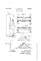
lO Figure 1 isv an elevation, showing one lform'of L the devicet linf use; i
i 'l Figure2sis. a.planl:view of .thisaform lofzthe Figure 3 is aside view :of the deviceshowmin Figure 2 with parts broken away and parts in vertical section;
Figure 4 is an end view;
Figure 5 is a transverse vertical section, taken at line 5 5 of Figure 3;
Figure 6 illustrates a modified form of the device.
Like parts are designated by like characters throughout the specification and drawing.
As shown in Figures 1 to 5, inclusive, the device comprises an exercising apparatus which may be supported upon a floor or any other foundation or base. As shown, the device is made of cast metal but it might be made of any other material and formed in any other way.
I, I are end members having laterally extended feet portions 2, 2. The end members may be perforated as at 3. The end members are joined by a rounded, longitudinally disposed member 4 which is of generally rounded and preferably semi-cylindrical shape. It may be reduced somewhat toward its ends as at 5, 5, where it joins the end members. If cast, the longitudinal member li may be provided with a reinforcing web 6, at-any suitable point intermediate its ends. Other reinforcement may, of
course, be provided.
As shown in Figure 6 the exercising member is mounted upon and preferably secured to a base l. A balancing member 8, having a handle 9, is
also secured to the base. Thus the exercising member and the balancing member are mounted on the same base and are movable together as a unit.
v To facilitate relative movement of the foot and exercising device, a flexible fabric member, such as a towel I0, may be provided.
Where the device is in its simpler form as shown in the first five figures, it is preferably placed for use adjacent some portion of the wall or other rigid member, by means of which the 'usermaylbalanceihimself. shown in'Figure 1,1the user I I is -balancinghimself'by holding to' 1 the door frame I2.
imA
`and 4 almodied' form is showniin whlchl the generally horizontal portion? 4,'5 5= is A'made separately1 from' the'baseportion I, 2, the parts being -separated-and t-hefbase portions bei-nggpinned to the horizontal portion by pins I3, fixed -in the 10 construction nor to any particular material.
The use and operation of the invention are as follows:
In general the device may be used in either 20 form and when used, the user, without shoes, stands with the longitudinal member supporting his weight, preferably upon the arch of his foot.
He balances himself either by holding the handle 9 in the form of the device shown in Figure 6, 25 or by holding or touching some other stationary member such as a door frame or Wall, and holding his body preferably as nearly erect as possible, moves his feet backwards and forwards, from the position shown in Figure 1 in full lines 30 to the position shown in dotted lines at X, in which the heel points downward and the toes are raised above the heel. He then moves his feet forward to the position shown at Y in Figure l, where the toes are pointed downward and the 35 heel raised above the toes. This relative movement of the feet with respect to the support 4, 5, exercises and massages the muscles of the feet as the foot slides or rolls across the member upon which it rests. 40
If the fabric member I0 is used, the user stands upon it and it serves to reduce friction of the foot and to make the movement just described easier.
The movement of the feet described necessitates bending and flexing of the foot itself, exer- 45 cise of the foot muscles and bending and flexing of the muscles of the legs generally, with the result that the muscles are exercised and strengthened, the circulation increased and benefited and the muscular, bony and nervous structure of the 50 feet and legs as a whole exercised, strengthened and improved.
The particular types of movements illustrated in Figure 1 represent only some of those possible. Many other exercises are possible. The purpose 55 generally is to provide a device upon which the user supports his weight intermediate the ends of his feet and thus carries his weight possibly on the arch of the foot, possibly on the ball of the foot or elsewhere; and with which device he can exercise that portion of the foot by many different movements and manipulations. He is not limited, and the invention is not limited, to the idea of merely rocking or sliding or rolling back and forth with the feet on the support. Trans- Verse rolling, rocking and bending of the feet are possible and is contemplated in addition to the mere backward and forward movement illustrated. It is to be understood, of course, that the use of the towel or cloth l0 is optional. In general that serves to make movement of the foot with respect to the support easier, but it is not essential and the apparatus may be used Without it.
It will be noticed that the upper surface of the support 4 upon Which the user stands is reduced adjacent each end as at 5, 5. These reduced portions serve to provide places for the feet. In a sense, therefore, they are positioning depressions on the surface of the support. While the support might be of constant size and be free from these depressions, their presence is useful because it tends to position the feet and to retain them in position and thus to simplify the use of the device.
The device as shown might be modified by substituting in place of the fixed member 4, 5, a roller of any suitable size and contour so that the user might merely rock back and forth and the roller would roll under his weight to produce an effect generally the same as that produced when he rocks back and forth on the present fixed support member 4, 5.
Where in the specification and claim I have referred to a floor, it is to be understood that I mean any support for the apparatus. Ordinarily the apparatus will be used indoors and will rest upon the floor of the room within which it is used. It might, of course, be used out of doors and might rest upon any support or base. Where I have referred to the fact that it rests upon the oor or is supported above the oor, I mean any base which could be used to carry the apparatus,
I have spoken of using the iiexible member I0 and it is illustrated in Figures 1 and 5. It is to'x be understood that it could be used equally well with the form of the device shown in Figure 6. It has been omitted from that figure because of the small scale used and to avoid confusion in the showing.
I claim:
In an exerciser apparatus, a single stationary ground-engaging supporting member, said supporting member being provided, on its upper surface, with an extended generally rounded foot receiving portion which is generally arcuate in vertical transverse contour, said surface being positioned a distance above the floor sumcient to permit a user, standing upon said arcuate surface, to rock back and forth with respect to said supporting member without contact with the floor, the radius of the arc of said supporting surface being suilcient to permit a substantial portion of the lower surface of the foot simultaneously to contact it without an undue flexure of the foot.
CARL HUGO GERLOFSON.
Priority Applications (1)
| Application Number | Priority Date | Filing Date | Title |
|---|---|---|---|
| US50339A US2082829A (en) | 1935-11-18 | 1935-11-18 | Exercise apparatus |
Applications Claiming Priority (1)
| Application Number | Priority Date | Filing Date | Title |
|---|---|---|---|
| US50339A US2082829A (en) | 1935-11-18 | 1935-11-18 | Exercise apparatus |
Publications (1)
| Publication Number | Publication Date |
|---|---|
| US2082829A true US2082829A (en) | 1937-06-08 |
Family
ID=21964682
Family Applications (1)
| Application Number | Title | Priority Date | Filing Date |
|---|---|---|---|
| US50339A Expired - Lifetime US2082829A (en) | 1935-11-18 | 1935-11-18 | Exercise apparatus |
Country Status (1)
| Country | Link |
|---|---|
| US (1) | US2082829A (en) |
Cited By (6)
| Publication number | Priority date | Publication date | Assignee | Title |
|---|---|---|---|---|
| US2638088A (en) * | 1950-11-24 | 1953-05-12 | Robert F Johnson | Appliance for massaging and exercising human feet |
| US4539977A (en) * | 1980-12-03 | 1985-09-10 | Schneider Sr Paul E | Therapeutic support means |
| US6210302B1 (en) * | 1993-02-08 | 2001-04-03 | Karin R. Globus | Exercising device and method of using same |
| US6425843B1 (en) * | 1998-04-08 | 2002-07-30 | Leesa Storfer | Apparatus for stretching the calf muscles |
| US20040054305A1 (en) * | 2000-10-27 | 2004-03-18 | Torbjorn Berglund | Method and a device for preventing and treating ligament injuries in the lower extremities |
| US9649246B1 (en) * | 2012-01-25 | 2017-05-16 | Ronald B. Johnson | Massage device and removeable mounting system |
-
1935
- 1935-11-18 US US50339A patent/US2082829A/en not_active Expired - Lifetime
Cited By (7)
| Publication number | Priority date | Publication date | Assignee | Title |
|---|---|---|---|---|
| US2638088A (en) * | 1950-11-24 | 1953-05-12 | Robert F Johnson | Appliance for massaging and exercising human feet |
| US4539977A (en) * | 1980-12-03 | 1985-09-10 | Schneider Sr Paul E | Therapeutic support means |
| US6210302B1 (en) * | 1993-02-08 | 2001-04-03 | Karin R. Globus | Exercising device and method of using same |
| US6306064B2 (en) * | 1993-02-08 | 2001-10-23 | Karin R. Globus | Exercising device and method of using same |
| US6425843B1 (en) * | 1998-04-08 | 2002-07-30 | Leesa Storfer | Apparatus for stretching the calf muscles |
| US20040054305A1 (en) * | 2000-10-27 | 2004-03-18 | Torbjorn Berglund | Method and a device for preventing and treating ligament injuries in the lower extremities |
| US9649246B1 (en) * | 2012-01-25 | 2017-05-16 | Ronald B. Johnson | Massage device and removeable mounting system |
Similar Documents
| Publication | Publication Date | Title |
|---|---|---|
| US3572701A (en) | Push pull type exercising device | |
| US2315485A (en) | Exercising device | |
| US3205888A (en) | Exercise and vibration machine | |
| US3636946A (en) | Exercising apparatus | |
| US3586322A (en) | Combined rowing apparatus and exercising apparatus | |
| KR101948760B1 (en) | Smart Leg Movement Stimulator Device | |
| US3381958A (en) | Hand and foot exercising device | |
| US3637206A (en) | Endless belt exerciser with accelerating and decelerating tread surfaces | |
| US3707285A (en) | Horizontal bar exercising device | |
| US4126308A (en) | Combination pommel horse and rotatable wheel mounted leg support device | |
| US2783045A (en) | Push and pull exerciser | |
| US3716231A (en) | User controlled exerciser frame | |
| US3672670A (en) | Wheeled foot-exercising device with hand grips | |
| US3784192A (en) | Wheel supported exercising device | |
| US2638089A (en) | Foot exerciser | |
| US3767191A (en) | Practice pommel horse assembly | |
| US4595197A (en) | Wheeled exercise device | |
| US3606321A (en) | Elastic type leg exercising device | |
| US2082829A (en) | Exercise apparatus | |
| KR101898841B1 (en) | Smart Leg Movement Stimulator Device | |
| TW200306220A (en) | Swinging implement | |
| US3544103A (en) | Resilient cradle exercise apparatus | |
| US3863916A (en) | Exercising devices | |
| US3912262A (en) | Gymnastic, recreational and instructional apparatus | |
| KR20210042232A (en) | Squat exercise apparatus |