US2071925A - Ship construction - Google Patents
Ship construction Download PDFInfo
- Publication number
- US2071925A US2071925A US59212A US5921236A US2071925A US 2071925 A US2071925 A US 2071925A US 59212 A US59212 A US 59212A US 5921236 A US5921236 A US 5921236A US 2071925 A US2071925 A US 2071925A
- Authority
- US
- United States
- Prior art keywords
- longitudinal
- bulkheads
- webs
- points
- stiffeners
- Prior art date
- Legal status (The legal status is an assumption and is not a legal conclusion. Google has not performed a legal analysis and makes no representation as to the accuracy of the status listed.)
- Expired - Lifetime
Links
- 238000010276 construction Methods 0.000 title description 18
- 239000003351 stiffener Substances 0.000 description 55
- 238000007747 plating Methods 0.000 description 17
- 238000005452 bending Methods 0.000 description 14
- 238000009432 framing Methods 0.000 description 12
- 238000012986 modification Methods 0.000 description 9
- 230000004048 modification Effects 0.000 description 9
- 238000010008 shearing Methods 0.000 description 7
- 238000000034 method Methods 0.000 description 5
- 238000003466 welding Methods 0.000 description 4
- 239000007788 liquid Substances 0.000 description 3
- 230000014509 gene expression Effects 0.000 description 2
- 239000000463 material Substances 0.000 description 2
- 239000002184 metal Substances 0.000 description 2
- XLYOFNOQVPJJNP-UHFFFAOYSA-N water Substances O XLYOFNOQVPJJNP-UHFFFAOYSA-N 0.000 description 2
- 238000006243 chemical reaction Methods 0.000 description 1
- 230000006835 compression Effects 0.000 description 1
- 238000007906 compression Methods 0.000 description 1
- 238000005520 cutting process Methods 0.000 description 1
- 230000007547 defect Effects 0.000 description 1
- 238000009826 distribution Methods 0.000 description 1
- 238000007667 floating Methods 0.000 description 1
- 230000001771 impaired effect Effects 0.000 description 1
- 238000005304 joining Methods 0.000 description 1
- 238000004519 manufacturing process Methods 0.000 description 1
- 230000007935 neutral effect Effects 0.000 description 1
- 238000007665 sagging Methods 0.000 description 1
- 150000003839 salts Chemical class 0.000 description 1
Images
Classifications
-
- B—PERFORMING OPERATIONS; TRANSPORTING
- B63—SHIPS OR OTHER WATERBORNE VESSELS; RELATED EQUIPMENT
- B63B—SHIPS OR OTHER WATERBORNE VESSELS; EQUIPMENT FOR SHIPPING
- B63B3/00—Hulls characterised by their structure or component parts
- B63B3/14—Hull parts
-
- B—PERFORMING OPERATIONS; TRANSPORTING
- B63—SHIPS OR OTHER WATERBORNE VESSELS; RELATED EQUIPMENT
- B63B—SHIPS OR OTHER WATERBORNE VESSELS; EQUIPMENT FOR SHIPPING
- B63B3/00—Hulls characterised by their structure or component parts
- B63B3/14—Hull parts
- B63B3/26—Frames
- B63B3/32—Web frames; Web beams
-
- B—PERFORMING OPERATIONS; TRANSPORTING
- B63—SHIPS OR OTHER WATERBORNE VESSELS; RELATED EQUIPMENT
- B63B—SHIPS OR OTHER WATERBORNE VESSELS; EQUIPMENT FOR SHIPPING
- B63B3/00—Hulls characterised by their structure or component parts
- B63B3/14—Hull parts
- B63B3/26—Frames
- B63B3/34—Frames of longitudinal type; Bulkhead connections
-
- B—PERFORMING OPERATIONS; TRANSPORTING
- B63—SHIPS OR OTHER WATERBORNE VESSELS; RELATED EQUIPMENT
- B63B—SHIPS OR OTHER WATERBORNE VESSELS; EQUIPMENT FOR SHIPPING
- B63B3/00—Hulls characterised by their structure or component parts
- B63B3/14—Hull parts
- B63B3/56—Bulkheads; Bulkhead reinforcements
- B63B3/60—Bulkheads; Bulkhead reinforcements with curved or corrugated plating
Definitions
- My invention relates to improvements in the structure of floating vessels or ships of all types, but especially to- Vessels designed to carry liquid cargo in bulk, commonly called tankers, and built on the quasi longitudinal system of framing.
- angle bulbs are the more desirable form of stiffening members, but owing to limitations of manufacture, they are not always available in the larger sizes. be able to make a more extended use of desirable commercial shapes, such as angle bulbs, when the greatest section modulus available in said angle bulbs is less than the section modulus required at the points of support.
- Another object of my invention is to provide continuity of strength in the longitudinals of the ships framing where cut by the bulkheads.
- Still another object of my invention is to provide continuity of strength in the longitudinals of the ships framing where cut by the bulkheads by welding metal to connect the ends of the longitudinals where so out.
- Another object of my invention is to reduce to normal the unit stresses developed in the ships plating at the line of the transverse bulkheads and the transverse web members.
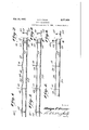
- Fig. 1 is a partial section through a vessel illustrating one form of longitudinal embodying my invention
- Fig. 2 is a cross-section taken along the line 2-2 of Fig. 1;
- Fig. 3 is a modification of Fig. 1;
- Fig. 4 is a cross-section taken along the line 44 of Fig. 3;
- Fig. 5 is another modification of Fig. 1;
- Fig. 6 is a cross-section taken along the line 66 of Fig. 5;
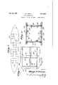
- Fig. 7 is a diagrammatic layout of a hold plan of a vessel with transverse and longitudinal bulkheads adapted for longitudinal framing embodying my invention
- Fig. 8 is an enlarged cross-section in part of Fig. 7, and illustrates the longitudinal framing embodying my invention.
- Fig. 9 is a longitudinal section taken horizontally through a portion of the vessel shown in Fig. '7, and illustrates the embodiment of my invention to the ship's longitudinals.
- W Unit load on span in tons per foot of span.
- H Test head of water in feet, assumed applied to stiffener area.
- I Moment of inertia of stiffener with plating.
- Y Distance of neutral axis from inner edge of stiffener.
- F Unit stress.
- Figs. 1' to 6 inclusive show three constructions of longitudinal stiffening strength members designed to have greater continuity of strength by having greater uniformity in their resisting moment based on uniformity of stress as regards the points of support and midway of said points.
- the bulkheads l0 and the web beams II in each case are the points of support.
- I2 indicates the size of stiffener required for the midway of supports points of stress as calculated by the said midway support formula set forth above.
- I3 is a tie bar piercing Watertight the bulkhead Ill and attached as by welding to the inner edges of the cut ends of the stiifeners, and 23 are bulkhead boundary bars to which the out ends of the stiffeners are welded.
- I may calculate for the section modulus required at this point of support by using solely therefor the sectional area of the tie bar positioned along the inner edge of the stiffener and the area of the plating between the cut ends of the stiffeners at the outer edges. To get the same strength into the stiffeners at the web beam points of support, I modify the stiffeners at these points.
- Figs. 1 and 2 I show one modification wherein the stiffener I4 is comprised of a plate web 15, or the like, swelled out as at IE5 at the points of Web beam support, and a round section if, or the like, welded to the inner edge of the plate Web I 5..
- Figs. 3 and 4 I show another modification of my invention in which the stiffener I8 is comprised of an angle bulbsection, or the like, with the web split near the inner edge as at [9 at the points of web beam support and with the inner edge portion at these points bowed inwardly to increase the width of the stiffener, and the resulting aperture filled in by welding.
- Figs. 5 and 6 I show another modification of my invention in which the stiffener 2!] of angle bulb section, or the like, is strengthened at the:
- I may approximate in a practicable manner the theoretical requirements for strength by extending the member l3 or 21 to the nearest points along the stifieners at which the bending moment is not greater than that at the midway point. Expressed as a matter of practice and to take care of a certain variation in the spacing of the spans, I prefer to make the length of the reenforcings I3, iii, i9, and 28 extend to either side of the points of support a distance not less than 10% nor more than 21% of the distance between two adjoining supports.
- Fig. '7 I have shown diagrammatically a hold plan of a type of vessel particularly adapted for embodying my invention.
- the vessel would be constructed with plating 22 on the bottom 2 sides 25, and deck 26, on the quasi longitudinal system of framing, especially designed to carry a liquid cargo in bulk, It would comprise a plurality of tanks 27 formed by longitudinal bulkheads 28 and closely spaced transverse bulkheads 29 attached to the ships plating 25 and to the longitudinal bulkheads 28.
- the transverse bulkheads 29 would comprise the plating ill and the boundary bars 23 of Fig. 1.
- the framing of the vessel would comprise relatively deep and widely spaced transverse webs ll attached to the ships plating and to the longitudinal bulkheads.
- the framing would also comprise relatively narrow and closely spaced longitudinal stiffeners 313.
- the said stifieners 353 would comprise the members i l of Fig. l or its hereinbefore described modifications.
- transverse bulkheads fore and aft walls, webs in widely spaced transverse planes attached to said walls, relatively narrow longitudinal stiffeners passing continuous through said webs and cut through by said bulkheads in such a manner that the cut ends are in close proximity to said buikheads on each side thereof, and a reenforcing bar secured to the inner edge of each of the said longitudinal stiffeners and passing continuous through said webs to each side thereof a distance of not less than nor more than 21% of the distance to the next adjacent support.
- a longitudinal stiffener supported by webs and bulkheads characterized by having a normal section of sufficient strength to resist a predetermined unit stress at a point midway between its supports, and being reenforced along its inner edge to each side of said supports a distance not less than 19% nor more than 21% of the distance to the next adjacent support, said reenforcement comprising a bar welded to said inner edge of said longitudinal stifiener of sufficient strength in combination with said longitudinal stiffener to resist a predetermined unit stress at the point of support, said latter unit stress being of the same value as the first mentioned unit stress.
- each of said stiffeners comprising a plate bowed out in width on the inner edge in way of said webs, said bowing extending to each side of the webs a distance not less than 10% nor more than 21% of the distance to the next adjacent support, and a reenforcing bar welded to the inner edge of each of said stiifeners.
- transverse bulkheads fore and aft walls, webs in widely spaced transverse planes attached to said walls, and longitudinal stiffeners supported at said bulkheads and said webs, each of said stiffeners comprising a plate bowed out in width on the inner edge in way of said webs, said bowing extending to each side of the webs a distance not less than 10% nor more than 21% of the distance to the next adjacent support, and a round bar welded to the inner edge of each of said stifieners.
- each of said stiffeners comprising a bulb section with the bulb along the inner edge thereof and having the web of said bulb section increased in width in way of said web beams by splitting the web of the bulb section near the bulb and bowing the bulb inwardly, said bowing extending to each side of the webs a distance not less than 10% nor more than 21%of the distance to the next adjacent support, and weld metal deposited in the aperture resulting from the bowing of the bulb.
- transverse bulkheads fore and aft walls, webs in widely spaced transverse planes attached to said walls, and longitudinal stifieners supported at said bulkheads and said webs, each of said stifieners comprising a bulb section, and reenforcing bars fused onto the inner edge of said bulb section in way of said webs, said reenforcing bars extending to each side of the webs a distance not less than 10% nor more than 21% of the distance to the next adjacent support.
- transverse bulkheads fore and aft walls, Webs in widely spaced transverse planes attached to said walls, and longitudinal stiffeners supported at said bulkheads and said webs, each of said stiffeners comprising a standard rolled section, and reenforcing bars welded onto the inner edge of said rolled section in way of the webs, said reenforcing bars extending to each side of the webs a distance not less than 10% nor more than 21% of the distance to the next adjacent support.
- each of said stiffeners comprising a standard rolled section, and reenforcing means added to said rolled section in way of the said points of support in such a manner as to be functionally integral with said stiffener, said reenforcing means extending to each side of the points of support a distance not less than 10% nor more than 21% of the distance to the next adjacent support.
- each of said stiffeners comprising a standard rolled section, and reenforcing means added to said rolled section in way of the said webs in such a manner as to be functionally integral with said stilfeners, said reenforcing means extending to each side of the webs a distance not less than 10% nor more than 21% of the distance to the next adjacent support.
- transverse bulkheads fore and aft walls, webs in widely spaced transverse planes attached to said walls, boundary bars attaching said bulk heads to said walls, and longitudinal stiffeners continuous through said webs and cut through by said bulkheads in such a manner that the cut ends are in close proximity to said bulkheads on each side thereof, said stiifeners being attached to said webs and to said walls, each of said stiffeners comprising round tie rods piercing watertight said bulkheads and joining said out ends of said stiifeners by being attached to the inner flanges thereof, said out ends of said stiifeners being welded at the outer flanges thereof to said boundary bars so as to be functionally integral therewith, and reenforcing means added to each of said stiifeners in way of said webs so as to be functionally integral therewith, said reenforcing means extending to each side of the Webs a distance not less than 10% nor more than 21% of
Landscapes
- Chemical & Material Sciences (AREA)
- Engineering & Computer Science (AREA)
- Combustion & Propulsion (AREA)
- Mechanical Engineering (AREA)
- Ocean & Marine Engineering (AREA)
- Filling Or Discharging Of Gas Storage Vessels (AREA)
Description
Feb. 23, 1937. q H, F R 2,071,925
SHIP CONSTRUCTION Original Filed July 19, 1934 2 Sheets-Sheet 1 SHIP CONSTRUCTION Original Filed July 19, 1934 2 Sheets-Sheet. 2
Patented Feb. 23, 193'? UNITED STATES SHIP CONSTRUCTION Hugo P. Frear, New York, N. Y., assignor to Bethlehem Shipbuilding Corporation, Ltd, a corporation of Delaware Original application July 19, 1934, Serial No. 735,923. Divided and this application January 15, 1936, Serial No. 59,212
11 Claims.
My invention relates to improvements in the structure of floating vessels or ships of all types, but especially to- Vessels designed to carry liquid cargo in bulk, commonly called tankers, and built on the quasi longitudinal system of framing.
The present application is acontinuation-inpart of my co-pending application Serial No. 688,574, filed September 8, 1933, and is a divisional application of my co-pending application Serial No. 735,923, filed July 19, 1934, and which has matured into Patent No. 2,053,904.
In vessels constructed to carry liquid. cargo in bulk the machinery is usually located aft. This necessitates a distribution of cargo on account of which the greatest overall stresses in the plating are in the sagging condition as when the vessel is in the hollow of a wave in which condition the deck plating is incompression and the bottom plating is in tension. In longitudinally framed vessels the continuity of strength in the plating is greatly impaired due to the fact that the longitudinal stiffeners attached to the plating are cut through by the bulkheads, thereby causing discontinuity and harmful concentration of stress in the plating in way of said bulkheads, resulting in cracks in the plating and leaking rivets at the end of the longitudinals.
Many means have been suggested to compensate for the said discontinuity and concentration of stress due to cutting the longitudinals. Most of these means have only been partially successful due to said means employed at the inner edges of the longitudinals being inadequate and eccentrically loaded or by reason of the fitting of doublings at the outer edge of the longitudinals designed to strengthenthe plating rather than correct the cause of said discontinuity by tieing the ends of the longitudinals on each side of the bulkheads together. It would seem rather obvious that if continuity of the longitudinals where cut at the bulkheads is to be restored, that both the inner and outer edges shouldbe connected to give a balanced cross-section, and that the means employed at the outer edge should preferably be something other than mere attachment to or receipt of strength from the same plating that the longitudinal is intended to strengthen. Furthermore, actual experience-has shown that rivet connections to the cut longitudinal ends do not stand the test of time.
Another feature common in ship design is to make the longitudinal stiifeners of uniform cross-section notwithstanding the fact that there is a great discrepancy in both the bending and the shearing stresses at different points in the length of the longitudinal stiffener, and that the maximum bending and shearing stresses coincide at the bulkheads and at the web beams. The bending stresses midway between the bulkheads andthe. web beams, or midway. of each span of (Ci. lid-79) the longitudinal stiffener are not only very much less than at the ends of the span but the shearing stresses in both the longitudinal stifiener and in the rivets attaching the longitudinal stiffener at this midway point are reduced to zero. From applied mechanics and experience we know that a strength member is stronger longitudinally when the unit stresses throughout are uniform rather than otherwise, and that a member acting longitudinally either under. tension or compression is stronger when free from bending or shearing stresses. It is obvious therefor that a more efiicient longitudinal stiffener results when it is so designed as regards cross-sectional area that it is more nearly uniformly stressed throughout its length regardless of the varying bending moments at the supports and midway of the said supports.
As noted above it has been common herebefore to make the longitudinal stifieners of uniform cross-section and. it has also been the practice to determine this cross-section by the demands for suitable strength required at the supports, or points of intersection of the longitudinal stiffeners with the bulkheads and Web frames. procedure has resulted ina considerable weight in the longitudinal stiiieners that was not efficiently made use of. It is the primary object of my invention to eliminatethis useless weight tothe end that I have a longitudinal stiffener that is designed to be more uniformly stressed at its points of varying reactions when acting as a beam whereby its efficiency as a beam is improved and a considerable saving in weight may. be had. This saving in weight or" the framing of the ship over the usual framing results not only in the initial saving in cost but in future savings due to added capacity and reduced tolls.
It is well known in the ship building art that angle bulbs are the more desirable form of stiffening members, but owing to limitations of manufacture, they are not always available in the larger sizes. be able to make a more extended use of desirable commercial shapes, such as angle bulbs, when the greatest section modulus available in said angle bulbs is less than the section modulus required at the points of support.
Another object of my invention is to provide continuity of strength in the longitudinals of the ships framing where cut by the bulkheads.
Still another object of my invention is to provide continuity of strength in the longitudinals of the ships framing where cut by the bulkheads by welding metal to connect the ends of the longitudinals where so out.
Another object of my invention is to reduce to normal the unit stresses developed in the ships plating at the line of the transverse bulkheads and the transverse web members.
The novel features will be more fully under- Such- It is an object of my invention tov stood from the following description and claims taken with the drawings, in which:
Fig. 1 is a partial section through a vessel illustrating one form of longitudinal embodying my invention;
Fig. 2 is a cross-section taken along the line 2-2 of Fig. 1;
Fig. 3 is a modification of Fig. 1;
Fig. 4 is a cross-section taken along the line 44 of Fig. 3;
Fig. 5 is another modification of Fig. 1;
Fig. 6 is a cross-section taken along the line 66 of Fig. 5;
Fig. 7 is a diagrammatic layout of a hold plan of a vessel with transverse and longitudinal bulkheads adapted for longitudinal framing embodying my invention;
Fig. 8 is an enlarged cross-section in part of Fig. 7, and illustrates the longitudinal framing embodying my invention; and
Fig. 9 is a longitudinal section taken horizontally through a portion of the vessel shown in Fig. '7, and illustrates the embodiment of my invention to the ship's longitudinals.
Referring to the accompanying Figures 1 to 9 inclusive, I shall now describe my method of improvement in continuity and uniformity of stresses throughout the length of the longitudinal stiffeners between and through the bulkheads. As I have stated hereinbefore, it has been customary to make the longitudinal stiffeners of uniform cross-section regardless of the fact that they are called upon to resist forces of considerable difference in intensity at different points on their length, due mainly to their acting as continuous beams uniformly loaded. In both shearing and bending the maximum stresses occur at the bulkheads and at the web beams, while midway of these points the bending stresses are much less and the shearing stresses on the rivets and longitudinals are reduced to zero. By proportioning the longitudinal stiffener at its points of greatest resistance and at its points of less resistance so as to maintain its stresses more nearly uniform, I gain the advantages of a vessel of greater strength and continuity on the same weight of material, or a vessel of equal strength on a less weight of material. Furthermore I am enabled to lower the bending and shearing stresses where maximum in order that more of the strength of the longitudinal will be available to apply to the longitudinal strength of the vessel as a whole.
I find that the above advantages can be realized if separate calculations for section moduli of the longitudinal stiffeners are made, respectively at the points of support (the bulkheads and the web beams) and midway between the points of support, by the following formulae:
Notation used in the formulae.
L=Length of span in feet.
W=Unit load on span in tons per foot of span.
H=Test head of water in feet, assumed applied to stiffener area.
S=Spacing in feet between stiffeners.
M=Bending moment in stiffener due to loading.
I=Moment of inertia of stiffener with plating.
Y=Distance of neutral axis from inner edge of stiffener.
= ,section modulus.
F=Unit stress. FZ=Moment of resistance. 35 cu. ft. of salt water=0ne ton (2240 pounds).
As is well known in good design the bending moment must equal the moment of resistance, on M =FZ. If we wish to keep the stress at the points of support the same as that midway of the supports, then we can figure for the relative values of section moduli from HHS for midway supports; and
for in way of supports. From which by cancelling out equivalent values we see that the section modulus midway of the supports is much less than that required in way of the supports.
In Figs. 1' to 6 inclusive, I show three constructions of longitudinal stiffening strength members designed to have greater continuity of strength by having greater uniformity in their resisting moment based on uniformity of stress as regards the points of support and midway of said points. The bulkheads l0 and the web beams II in each case are the points of support. In each case I2 indicates the size of stiffener required for the midway of supports points of stress as calculated by the said midway support formula set forth above. In each case I3 is a tie bar piercing Watertight the bulkhead Ill and attached as by welding to the inner edges of the cut ends of the stiifeners, and 23 are bulkhead boundary bars to which the out ends of the stiffeners are welded. By use of the support formula set forth above I may calculate for the section modulus required at this point of support by using solely therefor the sectional area of the tie bar positioned along the inner edge of the stiffener and the area of the plating between the cut ends of the stiffeners at the outer edges. To get the same strength into the stiffeners at the web beam points of support, I modify the stiffeners at these points.
In Figs. 1 and 2 I show one modification wherein the stiffener I4 is comprised of a plate web 15, or the like, swelled out as at IE5 at the points of Web beam support, and a round section if, or the like, welded to the inner edge of the plate Web I 5..
In Figs. 3 and 4 I show another modification of my invention in which the stiffener I8 is comprised of an angle bulbsection, or the like, with the web split near the inner edge as at [9 at the points of web beam support and with the inner edge portion at these points bowed inwardly to increase the width of the stiffener, and the resulting aperture filled in by welding.
In Figs. 5 and 6 I show another modification of my invention in which the stiffener 2!] of angle bulb section, or the like, is strengthened at the:
points of web beam support by the fusing, or welding, of a suitably sized round section 2|, or the like, to the inner edge of the stiffener 20.
All three types of longitudinal stiffeners that I have shown are continuous through and attached to the web beams II, and are attached to the plating 22.
Those familiar with calculations in ship design will recognize that my construction presents a case in which a beam having a plurality of equally spaced spans with fixed ends is uniformly statically loaded. With these conditions it is well known that the bending moments in the beam are greatest at the points of support (either at the bulkhead or at the web frames) and, that at points inward from any point of support a distance of approximately 21% ofthetotal distance between any two adjoining points of support the bending moments become zero, and such points of zero moments are called points of contra-flexure; and, that at the midway point between any two adjoining points of support the bending moment is approximately one half of that at the points of support. With these conditions in mind I design my beam (by modifications hereinbefore described) at the points of support in such a manner that the re sisting moment of the beam at these points of support are proportional to their required strength, and I then make the main portion of the beam of a commercial section having the proportional required strength for midway of the support. To those skilled in the art it will be readily seen that by means of modifications such as described for the web beam supports, as at it in Fig. 1 and is in Fig. 3, I may very closely approximate the theoretical requirements of strength, while at the bulkheads, as by means of the tie rod l3 and the welded ends of the stiffeners, and at 2! in Fig. 5, I may approximate in a practicable manner the theoretical requirements for strength by extending the member l3 or 21 to the nearest points along the stifieners at which the bending moment is not greater than that at the midway point. Expressed as a matter of practice and to take care of a certain variation in the spacing of the spans, I prefer to make the length of the reenforcings I3, iii, i9, and 28 extend to either side of the points of support a distance not less than 10% nor more than 21% of the distance between two adjoining supports.
In Fig. '7 I have shown diagrammatically a hold plan of a type of vessel particularly adapted for embodying my invention. The vessel would be constructed with plating 22 on the bottom 2 sides 25, and deck 26, on the quasi longitudinal system of framing, especially designed to carry a liquid cargo in bulk, It would comprise a plurality of tanks 27 formed by longitudinal bulkheads 28 and closely spaced transverse bulkheads 29 attached to the ships plating 25 and to the longitudinal bulkheads 28. The transverse bulkheads 29 would comprise the plating ill and the boundary bars 23 of Fig. 1. Referring now to Figs. 8 and 9, the framing of the vessel would comprise relatively deep and widely spaced transverse webs ll attached to the ships plating and to the longitudinal bulkheads. The framing would also comprise relatively narrow and closely spaced longitudinal stiffeners 313. The said stifieners 353 would comprise the members i l of Fig. l or its hereinbefore described modifications.
It will be clear to those skilled in the art that the principle of reenforcing as hereinbefore described may be applied to other stifiener members with similar useful results. It may, for example, be applied to a transverse stiffener such as is shown in Fig. 9, wherein 3! is the stiffener, 32 are the web frames, and 33 are the reenforcing bars. The stiffeners 36, as shown, are not extended to be attached to or supported by the ships walls 22 but are substantially short thereof. This latter feature is not a part of this application but is disclosed and claimed in my pending application Serial No. 731,239, filed June 19, 1934. It is apparent, of course, that the ends of the stiffener 3! could be extended to be attached to and/or supported by the walls 22 in a manner similar to that shown for the ends of the stiffeners Hi.
From the foregoing description it will be easily seen that I have a novel method of ship construction which is economical and particularly remedies defects which are inherent in prior methods of constructing a vessel in accordance with the so-called longitudinal system of framing. I do not wish it to be understood that my above described methods are limited in their application to vessels of the latter construction and it is manifest that certain of the structures are useful in connection with other well known types of. ship construction.
The termsand expressions which I have employed are used as terms of description and not of limitation,.and I have no intention, in the use of such terms and expressions, of exciuding any equivalents of the features thereof, but recognize that various modifications are possible within the scope of the inventions claimed.
Having thus described my invention what I claim as new and desire to secure-by Letters Patent, is:
1. In a vessel of quasi longitudinal construction, transverse bulkheads, fore and aft walls, webs in widely spaced transverse planes attached to said walls, relatively narrow longitudinal stiffeners passing continuous through said webs and cut through by said bulkheads in such a manner that the cut ends are in close proximity to said buikheads on each side thereof, and a reenforcing bar secured to the inner edge of each of the said longitudinal stiffeners and passing continuous through said webs to each side thereof a distance of not less than nor more than 21% of the distance to the next adjacent support.
2. In a ship structure, a longitudinal stiffener supported by webs and bulkheads characterized by having a normal section of sufficient strength to resist a predetermined unit stress at a point midway between its supports, and being reenforced along its inner edge to each side of said supports a distance not less than 19% nor more than 21% of the distance to the next adjacent support, said reenforcement comprising a bar welded to said inner edge of said longitudinal stifiener of sufficient strength in combination with said longitudinal stiffener to resist a predetermined unit stress at the point of support, said latter unit stress being of the same value as the first mentioned unit stress.
3. In a vessel of quasi longitudinal construction, transverse bulkheads, fore and aft walls, webs in widely spaced transverse planes attached to said walls, and longitudinal stifieners supported at said bulkheads and said webs, each of said stiffeners comprising a plate bowed out in width on the inner edge in way of said webs, said bowing extending to each side of the webs a distance not less than 10% nor more than 21% of the distance to the next adjacent support, and a reenforcing bar welded to the inner edge of each of said stiifeners.
4. In a vessel of quasi longitudinal construction, transverse bulkheads, fore and aft walls, webs in widely spaced transverse planes attached to said walls, and longitudinal stiffeners supported at said bulkheads and said webs, each of said stiffeners comprising a plate bowed out in width on the inner edge in way of said webs, said bowing extending to each side of the webs a distance not less than 10% nor more than 21% of the distance to the next adjacent support, and a round bar welded to the inner edge of each of said stifieners.
5. In a vessel of quasi longitudinal construction, transverse bulkheads, fore and aft walls, web beams in widely spaced transverse planes attached to said walls, and longitudinal stiffeners supported at said bulkheads and said Web beams, each of said stiffeners comprising a bulb section with the bulb along the inner edge thereof and having the web of said bulb section increased in width in way of said web beams by splitting the web of the bulb section near the bulb and bowing the bulb inwardly, said bowing extending to each side of the webs a distance not less than 10% nor more than 21%of the distance to the next adjacent support, and weld metal deposited in the aperture resulting from the bowing of the bulb.
6. In a vessel of quasi longitudinal construction, transverse bulkheads, fore and aft walls, webs in widely spaced transverse planes attached to said walls, and longitudinal stifieners supported at said bulkheads and said webs, each of said stifieners comprising a bulb section, and reenforcing bars fused onto the inner edge of said bulb section in way of said webs, said reenforcing bars extending to each side of the webs a distance not less than 10% nor more than 21% of the distance to the next adjacent support.
7. In a vessel of quasi longitudinal construction, transverse bulkheads, fore and aft walls, Webs in widely spaced transverse planes attached to said walls, and longitudinal stiffeners supported at said bulkheads and said webs, each of said stiffeners comprising a standard rolled section, and reenforcing bars welded onto the inner edge of said rolled section in way of the webs, said reenforcing bars extending to each side of the webs a distance not less than 10% nor more than 21% of the distance to the next adjacent support.
8. In a vessel of quasi longitudinal construction, transverse bulkheads, fore and aft walls, webs in widely spaced transverse planes attached to said walls, and longitudinal stiffeners supported at said bulkheads and said webs, each of said stiffeners comprising a standard rolled section, and reenforcing means added to said rolled section in way of the said points of support in such a manner as to be functionally integral with said stiffener, said reenforcing means extending to each side of the points of support a distance not less than 10% nor more than 21% of the distance to the next adjacent support.
9. In a vessel of quasi longitudinal construction, transverse bulkheads, fore and aft walls,
webs in widely spaced transverse planes attached to said walls, and longitudinal stiffeners supported at said bulkheads and said webs, each of said stiffeners comprising a standard rolled section, and reenforcing means added to said rolled section in way of the said webs in such a manner as to be functionally integral with said stilfeners, said reenforcing means extending to each side of the webs a distance not less than 10% nor more than 21% of the distance to the next adjacent support.
10. In a vessel of quasi longitudinal construction, transverse bulkheads, fore and aft walls, webs in widely spaced transverse planes attached to said walls, boundary bars attaching said bulk heads to said walls, and longitudinal stiffeners continuous through said webs and cut through by said bulkheads in such a manner that the cut ends are in close proximity to said bulkheads on each side thereof, said stiifeners being attached to said webs and to said walls, each of said stiffeners comprising round tie rods piercing watertight said bulkheads and joining said out ends of said stiifeners by being attached to the inner flanges thereof, said out ends of said stiifeners being welded at the outer flanges thereof to said boundary bars so as to be functionally integral therewith, and reenforcing means added to each of said stiifeners in way of said webs so as to be functionally integral therewith, said reenforcing means extending to each side of the Webs a distance not less than 10% nor more than 21% of the distance to the next adjacent support.
11. In a vessel of quasi longitudinal framing, transverse bulkheads, fore and aft walls, webs in widely spaced transverse planes attached to said walls, and longitudinal stiffeners supported at said bulkheads and said webs passing continuous through said webs and attached to said wall and to said webs, said stiffener comprising a standard rolled section weak with respect to the predetermined maximum stresses to be resisted in way of the webs but strong with respect to the predetermined maximum stresses to be resisted midway of the webs, and reenforcing means added to the said rolled section in way of the webs in such a way as to be functionally integral with said stilfener, said reenforcing means extending to each side of the webs a distance not less than 10% nor more than 21% of the distance to the
Priority Applications (1)
| Application Number | Priority Date | Filing Date | Title |
|---|---|---|---|
| US59212A US2071925A (en) | 1934-07-19 | 1936-01-15 | Ship construction |
Applications Claiming Priority (2)
| Application Number | Priority Date | Filing Date | Title |
|---|---|---|---|
| US735923A US2053904A (en) | 1934-07-19 | 1934-07-19 | Ship construction |
| US59212A US2071925A (en) | 1934-07-19 | 1936-01-15 | Ship construction |
Publications (1)
| Publication Number | Publication Date |
|---|---|
| US2071925A true US2071925A (en) | 1937-02-23 |
Family
ID=26738499
Family Applications (1)
| Application Number | Title | Priority Date | Filing Date |
|---|---|---|---|
| US59212A Expired - Lifetime US2071925A (en) | 1934-07-19 | 1936-01-15 | Ship construction |
Country Status (1)
| Country | Link |
|---|---|
| US (1) | US2071925A (en) |
Cited By (1)
| Publication number | Priority date | Publication date | Assignee | Title |
|---|---|---|---|---|
| US2506549A (en) * | 1942-03-14 | 1950-05-02 | Kervarrec Bernard | Framing construction for vessels |
-
1936
- 1936-01-15 US US59212A patent/US2071925A/en not_active Expired - Lifetime
Cited By (1)
| Publication number | Priority date | Publication date | Assignee | Title |
|---|---|---|---|---|
| US2506549A (en) * | 1942-03-14 | 1950-05-02 | Kervarrec Bernard | Framing construction for vessels |
Similar Documents
| Publication | Publication Date | Title |
|---|---|---|
| US2218688A (en) | Ship construction | |
| US2071925A (en) | Ship construction | |
| US2400771A (en) | Hull construction for surface boats and ships | |
| US2218689A (en) | Construction of vessels | |
| US2644418A (en) | Welded ship construction | |
| US2053904A (en) | Ship construction | |
| US2743694A (en) | Welded ship hull construction | |
| US2741208A (en) | Tank ship bulkhead and girder construction | |
| US2162822A (en) | Ship hull and method of constructing it | |
| US2103715A (en) | Ship construction | |
| USRE21359E (en) | Ship construction | |
| US2409212A (en) | Structural member | |
| US2053903A (en) | Ship construction | |
| US2021629A (en) | Coal barge | |
| US1933860A (en) | Truss weld system | |
| US2092504A (en) | Ship construction | |
| US1658336A (en) | Floating vessel | |
| US2030881A (en) | Vessel | |
| US1970913A (en) | Construction of ships | |
| JP3396340B2 (en) | Honeycomb panel hull structure | |
| US1821882A (en) | Ship construction | |
| US1831479A (en) | Construction of ships and other structures | |
| US2254561A (en) | Framework for metallic vessels | |
| US1952156A (en) | Ship hull construction | |
| US1933861A (en) | Hull for ship construction |