US20656A - Improvement in seeding-machines - Google Patents
Improvement in seeding-machines Download PDFInfo
- Publication number
- US20656A US20656A US20656DA US20656A US 20656 A US20656 A US 20656A US 20656D A US20656D A US 20656DA US 20656 A US20656 A US 20656A
- Authority
- US
- United States
- Prior art keywords
- attached
- seed
- rod
- frame
- rods
- Prior art date
- Legal status (The legal status is an assumption and is not a legal conclusion. Google has not performed a legal analysis and makes no representation as to the accuracy of the status listed.)
- Expired - Lifetime
Links
- 241000721671 Ludwigia Species 0.000 description 10
- 230000000875 corresponding Effects 0.000 description 4
- 210000004369 Blood Anatomy 0.000 description 2
- 239000008280 blood Substances 0.000 description 2
- 230000000881 depressing Effects 0.000 description 2
- 230000013707 sensory perception of sound Effects 0.000 description 2
Images

Classifications
-
- A—HUMAN NECESSITIES
- A01—AGRICULTURE; FORESTRY; ANIMAL HUSBANDRY; HUNTING; TRAPPING; FISHING
- A01B—SOIL WORKING IN AGRICULTURE OR FORESTRY; PARTS, DETAILS, OR ACCESSORIES OF AGRICULTURAL MACHINES OR IMPLEMENTS, IN GENERAL
- A01B69/00—Steering of agricultural machines or implements; Guiding agricultural machines or implements on a desired track
- A01B69/02—Ridge-marking or like devices; Checkrow wires; Accessories therefor
- A01B69/024—Ridge-marking or like devices; Checkrow wires; Accessories therefor adapted to cut and form a ridge or forrow in the soil surface, e.g. with a disc
Definitions
- This invention relates to an improvement in that class of seeding-machines by which seed is planted in hills and in check-rows, two rows being planted at the same time.
- the invention consists in a novel means employed for operating reciprocating seed-slides and markers, as hereinafter fully shown and described, whereby the distribution or dropping of the seed is placed entirely under the control of the driver, and consequently the even or uniform planting of the same is assured.
- E D is the driver's seat, placed on the frame A.
- E E are two seed-boxes, which are fitted in the front end of frame A.
- each slide, F is placed, each slide having a hole, a, made in it and working below a cut-off, b, which may be formed of brushes. (See Fig. l.)
- the bottoms c of the hopper have each a hole, (1, made through them, as shown clearly in Fig. 1.
- each slide F is attached to a rod, G, and the upper ends of these rods are attached to a shaft, H.
- a cross-rod, L To the back end of the rod K one end of a cross-rod, L, is attached, and the opposite end of this rod is attached to a rod, M, the front end of which is pivoted to a small shaft, g, attached to a platform, It, on the frame a.
- rod M has a pendent projection attached to it at about its center, and a friction-roller is fitted in its lower end, corresponding precisely with the pendantf and rollersf.
- the rod M extends to the back end of the frame A, and it is connected by a rod, It, with a frame, N, the
- the frame N is formed of two rods, l I, one at each side of the frame A, the back ends of the rods l being connected by a cross-rod, m.
- n n To the rod m two spade-like projections, n n, are attached, said projections being in line with the seed-boxes E E.
- O is a spiral spring, one end of which is attached to the shaft H, and the other end of the spring is attached to the platform h.
- P is a lever which is placed on the platform h. This lever has a crossbar, 0, at its back end, said bar 0 being directly underneath the cross-rod L.
- the shaft g has its hearings attached to a sliding plate, Q, which is fitted between guides M, placed transverselyon the platform IL, and an upright lever, B, which is pivoted to an upright, 19, on the platform, has its lower end attached to the sliding plate Q.
- S S are seed conveying tubes, which are placed one under each seed-box E. Each tube S is attached to an arm, T, and the front ends of these arms are pivoted to the thills G.
- a chain, U is also attached to each arm T, the upper ends of the chains being attached to the thills C or frame A.
- the seed is discharged from the seed-boxes E by the perforated slides F in the usual way,
- the slides F may be stopped at any time by merely placing the foot on the front end of lever P and depressing it, thereby raising the rods K M free from the cams J, and the dropping of the seed at certain points at variance with a regular movement may be attained by shifting the slide Q, and thereby moving the frictionrollers that bear upon the cams upon such cam that will produce the result, it being understood that the cams are placed on the axle in varying positions, and therefore by shifting the rods M K the dropping of the seed may be retarded or accelerated, as occasion may require.
- This lateral moving or shifting of the rods M K is performed by actuating the lever B by hand, while the rods are raised free from the cams by the foot of the driver on seat D. Simultaneously with the movement of the slides F and the dropping of the seed the projections n n are allowed to fall. These projections serve as markers, and designate the planted seed, and enable the driver to place or adjust the machine properly in commencing rows, and also to keep the rows even or at equal distances apart.
- markers have been previously used and arranged similar to the ones herein described. I therefore do not claim the markers, separately considered; nor do I claim the reciprocating seed-slides F, nor the seedconveying tubes S, for they also have been used; but,
- the markers n attached to the frame N, when said markers are used in connection with the cams J and rods M K for operating the seed-distributing device, and the whole arranged to operate as and for the purpose set forth.
Landscapes
- Life Sciences & Earth Sciences (AREA)
- Engineering & Computer Science (AREA)
- Mechanical Engineering (AREA)
- Soil Sciences (AREA)
- Environmental Sciences (AREA)
- Sowing (AREA)
Description
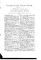
W. MOREHOUSE.
Corn-Planter.
Paterited? June 22, 1858.
limmnu mm ZET mum'- N.PETERS. PHOTO-UTHOGRAPHER. WASHINGTON. D a
UNITE States PATENT Fierce.
\V; MOREHOUSE, OF DAVENPORT, IOWA.
ilVlPROVEWlENT EN SEEDENG=MACHINE S To all whom it may concern:
Be it known that I, V. MOREHOUSE, of Davenport, in the county of Scott and State of Iowa, hat'einvented a new and Improved Seeding-Machine; and I do hereby declare that the following is a full, clear, and exact description of the same,reference being bad to the annexed drawings, making a part of this specification, in whichv Figure 1 is a side sectional elevation of my improvement, taken in the line a: :0, Fig. 2. Fig. 2 is a plan or top view of the same.
Similar letters of reference indicate corresponding parts in the two figures.
This invention relates to an improvement in that class of seeding-machines by which seed is planted in hills and in check-rows, two rows being planted at the same time.
The invention consists in a novel means employed for operating reciprocating seed-slides and markers, as hereinafter fully shown and described, whereby the distribution or dropping of the seed is placed entirely under the control of the driver, and consequently the even or uniform planting of the same is assured.
To enable those skilled in the art to fully understand and construct my invention, I will proceed to describe it.
Arepresents a horizontal frame, which is mounted on wheels B B.
U are thills attached to the front end of the frame A.
D is the driver's seat, placed on the frame A. E E are two seed-boxes, which are fitted in the front end of frame A.
At or over the bottom of each seed-box E a slide, F, is placed, each slide having a hole, a, made in it and working below a cut-off, b, which may be formed of brushes. (See Fig. l.)
The bottoms c of the hopper have each a hole, (1, made through them, as shown clearly in Fig. 1.
The back end of each slide F is attached to a rod, G, and the upper ends of these rods are attached to a shaft, H.
011 the axle I of the wheels B B a series of cams, J, are placed at each end, any proper number being used. These cams are all of the same form, having three arms or projections,
6; but they are placed in varying positions on the axle, as shown clearly in Fig. 1, one being placed slightly in advance of the other, and all at equal distances apart.
To the shaft Hthe front end of a rod, K, is pivoted. The back end of this rod is bent downward at a right angle with its other portion, as shown at f, and has a friction-roller, f, placed in its lower end.
To the back end of the rod K one end of a cross-rod, L, is attached, and the opposite end of this rod is attached to a rod, M, the front end of which is pivoted to a small shaft, g, attached to a platform, It, on the frame a. The
rod M has a pendent projection attached to it at about its center, and a friction-roller is fitted in its lower end, corresponding precisely with the pendantf and rollersf. The rod M extends to the back end of the frame A, and it is connected by a rod, It, with a frame, N, the
front end of which is jointed t0 the front end of frame A.
The frame N is formed of two rods, l I, one at each side of the frame A, the back ends of the rods l being connected by a cross-rod, m. To the rod m two spade-like projections, n n, are attached, said projections being in line with the seed-boxes E E.
O is a spiral spring, one end of which is attached to the shaft H, and the other end of the spring is attached to the platform h.
P is a lever which is placed on the platform h. This lever has a crossbar, 0, at its back end, said bar 0 being directly underneath the cross-rod L.
The shaft g has its hearings attached to a sliding plate, Q, which is fitted between guides M, placed transverselyon the platform IL, and an upright lever, B, which is pivoted to an upright, 19, on the platform, has its lower end attached to the sliding plate Q. S S are seed conveying tubes, which are placed one under each seed-box E. Each tube S is attached to an arm, T, and the front ends of these arms are pivoted to the thills G. A chain, U, is also attached to each arm T, the upper ends of the chains being attached to the thills C or frame A.
The operation is as follows: As the machine is drawn along the cams J and spring 0 actuate the shaft H, and the shaft operates the slides F through the medium of the rods G.
The seed is discharged from the seed-boxes E by the perforated slides F in the usual way,
and the tubes S convey the same to the earth,
the tubes being allowed to rise and fall to correspond to the inequalities of the ground. The slides F may be stopped at any time by merely placing the foot on the front end of lever P and depressing it, thereby raising the rods K M free from the cams J, and the dropping of the seed at certain points at variance with a regular movement may be attained by shifting the slide Q, and thereby moving the frictionrollers that bear upon the cams upon such cam that will produce the result, it being understood that the cams are placed on the axle in varying positions, and therefore by shifting the rods M K the dropping of the seed may be retarded or accelerated, as occasion may require. This lateral moving or shifting of the rods M K is performed by actuating the lever B by hand, while the rods are raised free from the cams by the foot of the driver on seat D. Simultaneously with the movement of the slides F and the dropping of the seed the proiections n n are allowed to fall. These proiections serve as markers, and designate the planted seed, and enable the driver to place or adjust the machine properly in commencing rows, and also to keep the rows even or at equal distances apart.
I am aware that markers have been previously used and arranged similar to the ones herein described. I therefore do not claim the markers, separately considered; nor do I claim the reciprocating seed-slides F, nor the seedconveying tubes S, for they also have been used; but,
Having thus described my invention, what I claim as new, and desire to secure by Letters Patent, is
1. The cams J, attached to the axle I, and laterally-moving rods K M, attached respectively to the shafts H g, the seed-slides F, be ing attached to the shaft H by rods G, and the shaft g, being attached to a slide-plate, Q,
the above parts operating as and for the purpose set forth.
2. The markers n, attached to the frame N, when said markers are used in connection with the cams J and rods M K for operating the seed-distributing device, and the whole arranged to operate as and for the purpose set forth.
WM. MOREHOUSE.
Witnesses:
(J. G. BLooD, H. S. SLAYMAKER.
Publications (1)
| Publication Number | Publication Date |
|---|---|
| US20656A true US20656A (en) | 1858-06-22 |
Family
ID=2085771
Family Applications (1)
| Application Number | Title | Priority Date | Filing Date |
|---|---|---|---|
| US20656D Expired - Lifetime US20656A (en) | Improvement in seeding-machines |
Country Status (1)
| Country | Link |
|---|---|
| US (1) | US20656A (en) |
Cited By (2)
| Publication number | Priority date | Publication date | Assignee | Title |
|---|---|---|---|---|
| US2618229A (en) * | 1947-02-25 | 1952-11-18 | Elvis T Knippel | Checking and marking attachment for planters |
| US4688386A (en) * | 1986-02-07 | 1987-08-25 | Lane Robert C | Linear release ice machine and method |
-
0
- US US20656D patent/US20656A/en not_active Expired - Lifetime
Cited By (2)
| Publication number | Priority date | Publication date | Assignee | Title |
|---|---|---|---|---|
| US2618229A (en) * | 1947-02-25 | 1952-11-18 | Elvis T Knippel | Checking and marking attachment for planters |
| US4688386A (en) * | 1986-02-07 | 1987-08-25 | Lane Robert C | Linear release ice machine and method |
Similar Documents
| Publication | Publication Date | Title |
|---|---|---|
| US13683A (en) | Improvement in seed-planters | |
| US20656A (en) | Improvement in seeding-machines | |
| US23980A (en) | Improvement in coan-planters | |
| US20301A (en) | Improvement in seeding-mach ines | |
| US12990A (en) | Improvement in seed-planters | |
| US56667A (en) | Improvement in corn-planters | |
| US28142A (en) | Improvement in seeding-machines | |
| US315245A (en) | Corn-planter | |
| US29100A (en) | Improvement in corn-planters | |
| US24687A (en) | Improvement in corn-planters | |
| US216163A (en) | Improvement in seed-planters | |
| US22171A (en) | Improvement in seeding-machines | |
| US18524A (en) | Improvement in seed-planters | |
| US19818A (en) | Improvement in seed-planters | |
| US270049A (en) | Check-row corn-planter | |
| US543530A (en) | Check-row planter and drill | |
| US43181A (en) | Improvement in corn-planters | |
| US20547A (en) | Improvement in seeding-machines | |
| US23371A (en) | Improvement in corn-planters | |
| US28917A (en) | Improvement in corn-planters | |
| US21958A (en) | Improvement in seeding-machines | |
| US57676A (en) | Improvement in corn-planters | |
| US411823A (en) | Corn-planter | |
| US32792A (en) | Improvement in seed-drills | |
| US21959A (en) | Improvement in seeding-machines |