US18524A - Improvement in seed-planters - Google Patents
Improvement in seed-planters Download PDFInfo
- Publication number
- US18524A US18524A US18524DA US18524A US 18524 A US18524 A US 18524A US 18524D A US18524D A US 18524DA US 18524 A US18524 A US 18524A
- Authority
- US
- United States
- Prior art keywords
- seed
- valve
- slide
- corn
- tube
- Prior art date
- Legal status (The legal status is an assumption and is not a legal conclusion. Google has not performed a legal analysis and makes no representation as to the accuracy of the status listed.)
- Expired - Lifetime
Links
- 240000008042 Zea mays Species 0.000 description 8
- 235000005824 Zea mays ssp. parviglumis Nutrition 0.000 description 8
- 235000002017 Zea mays subsp mays Nutrition 0.000 description 8
- 235000005822 corn Nutrition 0.000 description 8
- 241000196324 Embryophyta Species 0.000 description 3
- 239000002689 soil Substances 0.000 description 3
- 150000001875 compounds Chemical class 0.000 description 1
- 230000000994 depressogenic effect Effects 0.000 description 1
Images

Classifications
-
- A—HUMAN NECESSITIES
- A01—AGRICULTURE; FORESTRY; ANIMAL HUSBANDRY; HUNTING; TRAPPING; FISHING
- A01C—PLANTING; SOWING; FERTILISING
- A01C7/00—Sowing
- A01C7/02—Hand sowing implements
Definitions
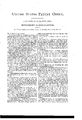
- FIG. 1 is a plan
- Fig. 2 a side view
- Fig. 3 a vertical central section, of a corn-plantin g plow constructed after my invention.
- my invention consists, for use, in connection with a planter to be propelled by hand, in the arrangement consisting of the doubleacting valves, compound lever, doublechambered hopper, adjustable pitman, and swinging self-adjusting roller, the whole being arranged and combined substantially as set forth, and serving to enable the operator to plant in hills by hand at each half-vibration of the valve, and when necessary to plant in drills by the revolution of the roller.
- A represents an ordinary plow-frame, which has arranged on top of its beam a seed-hopper, B.
- O is a drill-tube. It has a taper curved bar
- F is the seed-slide. It has two seed-holes, b a, one at its front end and the other at its rear end, as shown.
- the hole 1) drops seed as the moved forward until it arrives at a hill.
- F is a flexible cut-off at the center of the hopper.
- G is the valve in the lower end of the tube. It swings on a fulcrum, d. This valve is de signed, during check-row planting, for retaining the corn in the end of the tube until the proper time to allow it to escape into the soil. It also prevents the corn, owing to its being near the end of the tube, from being scattered in escaping.
- G is a handle or lever arranged alongside the handle of the plow, so as to be laid hold of by the hand when the plow-handle is taken hold of. It has its fulcrum at c, and is connected with the valve by a connecting-link,f, as shown.
- H is another lever. It has its fulcrum at g,
- I is a pitman-rod for operating the slide while planting in drills.
- the mechanism combining the slide and valve is detached from the slide and valve and the pitinan connected to the slide.
- the'valve stands vertically in the tube and the corn escapes into the soil on either side of it.
Landscapes
- Life Sciences & Earth Sciences (AREA)
- Soil Sciences (AREA)
- Environmental Sciences (AREA)
- Sowing (AREA)
Description
1.. B. SMITH.
Seed Planter.
Patented Oct. 27, 1857 N.FETERS. PmmllTHOGRAFHER WASHINGTON D c UNITED STATES PATENT OFFICE.
J. D. SMITH, or LANCASTER, OHIO.
IMPROVEMENT IN SEED-PLANTERS.
Specification forming part of Letters Patent No. 18,524, dated October 27, 1857.
hereby declare that the following is a full,
clear, and exact description of the same, reference being had to the annexed drawings,
forming part of this specification, in which- Figure 1 is a plan, Fig. 2 a side view, and Fig. 3 a vertical central section, of a corn-plantin g plow constructed after my invention.
Similar letters of reference indicate corresponding parts in the several figures.
The nature of my invention consists, for use, in connection with a planter to be propelled by hand, in the arrangement consisting of the doubleacting valves, compound lever, doublechambered hopper, adjustable pitman, and swinging self-adjusting roller, the whole being arranged and combined substantially as set forth, and serving to enable the operator to plant in hills by hand at each half-vibration of the valve, and when necessary to plant in drills by the revolution of the roller.
To enable others skilled in the art to make and use my invention, I will proceed to describe it.
A represents an ordinary plow-frame, which has arranged on top of its beam a seed-hopper, B.
O is a drill-tube. It has a taper curved bar,
. a, in front of it, which extends up from the crum, a, in order that the roller may rise and fall in passing over undulating soil.
F is the seed-slide. It has two seed-holes, b a, one at its front end and the other at its rear end, as shown. The hole 1) drops seed as the moved forward until it arrives at a hill.
slide moves back and the hole 0 as the slide moves forward.
F is a flexible cut-off at the center of the hopper.
G is the valve in the lower end of the tube. It swings on a fulcrum, d. This valve is de signed, during check-row planting, for retaining the corn in the end of the tube until the proper time to allow it to escape into the soil. It also prevents the corn, owing to its being near the end of the tube, from being scattered in escaping.
G is a handle or lever arranged alongside the handle of the plow, so as to be laid hold of by the hand when the plow-handle is taken hold of. It has its fulcrum at c, and is connected with the valve by a connecting-link,f, as shown.
H is another lever. It has its fulcrum at g,
and is connected with the handle G by a rod,
h, and to the slide by a similar rod, 6, as represented.
I is a pitman-rod for operating the slide while planting in drills.
Operation of planting in hills or check-rows.- The levers G and H being attached, as described, to the slide and valve, the machine is At this moment the lever G is depressed by the hand and the valve caused to form a receptacle for the corn at the front end of the tube and leave a space for the escape of the corn at the rear by standing diagonally across the tube. Simultaneously with this operation of the valve the seed-slide moves backward and drops corn into the receptacle. The lever is now raised and the valve made to form a receptacle at the rear of the tube and leave a space for the escape of the corn at the front by standing diagonally across the tube, but in an opposite manner to what it just did. As the corn first dropped by the slide escapes, another hill is deposited into the receptacle, ready for the next hill to be planted, and thus the operation proceeds until the field is planted. I
To plant in drills, the mechanism combining the slide and valve is detached from the slide and valve and the pitinan connected to the slide. During the operation of planting in drills the'valve stands vertically in the tube and the corn escapes into the soil on either side of it.
What I claim as my invention, and desire to secure by Letters Patent, is
The use, in connection with a planter to be propelled by hand, of the arrangement consisting of the double-acting valves F G, 0011]- pound levcr G H g h i, double-chambered hopper B F, adjustable pitinan I, and. swinging self-adjusting roller D, the whole being zirranged and combined substantially as set forth.
JOSEPH D. SMITH.
Witnesses:
P. B. EWING, J N0. D. MARTIN.
Publications (1)
| Publication Number | Publication Date |
|---|---|
| US18524A true US18524A (en) | 1857-10-27 |
Family
ID=2081913
Family Applications (1)
| Application Number | Title | Priority Date | Filing Date |
|---|---|---|---|
| US18524D Expired - Lifetime US18524A (en) | Improvement in seed-planters |
Country Status (1)
| Country | Link |
|---|---|
| US (1) | US18524A (en) |
-
0
- US US18524D patent/US18524A/en not_active Expired - Lifetime
Similar Documents
| Publication | Publication Date | Title |
|---|---|---|
| US30861A (en) | Improvement in corn-planters | |
| US18524A (en) | Improvement in seed-planters | |
| US25447A (en) | Improvement in seeding-machines | |
| US25556A (en) | Improvement in seed-planters | |
| US12990A (en) | Improvement in seed-planters | |
| US16617A (en) | Improvement in seed-planters | |
| US23481A (en) | Improvement in seeding-machines | |
| US21314A (en) | Improvement in seeding-machines | |
| US28615A (en) | Improvement in corn-planters | |
| US20656A (en) | Improvement in seeding-machines | |
| US29412A (en) | Improvement in corn-planters | |
| US18393A (en) | Improvement in seed-planters | |
| US24431A (en) | Improvement in seeding-machines | |
| US18999A (en) | Improvement in seed-planters | |
| US14144A (en) | Improvement in seed-planters | |
| US609354A (en) | Corn-planter | |
| US23071A (en) | Improvement in seed-planters | |
| US19953A (en) | Improvement in seed-planters | |
| US18346A (en) | Improvement in seeding-machines | |
| US20301A (en) | Improvement in seeding-mach ines | |
| US23371A (en) | Improvement in corn-planters | |
| US19198A (en) | Improvement in corn-planters | |
| US16198A (en) | Improvement in seed-planters | |
| US21393A (en) | Improvement in corn-planters | |
| US28943A (en) | Improvement in corn-planters |