US2028811A - Cutter chain - Google Patents
Cutter chain Download PDFInfo
- Publication number
- US2028811A US2028811A US677881A US67788133A US2028811A US 2028811 A US2028811 A US 2028811A US 677881 A US677881 A US 677881A US 67788133 A US67788133 A US 67788133A US 2028811 A US2028811 A US 2028811A
- Authority
- US
- United States
- Prior art keywords
- bit
- bore
- cutter
- bores
- cutter chain
- Prior art date
- Legal status (The legal status is an assumption and is not a legal conclusion. Google has not performed a legal analysis and makes no representation as to the accuracy of the status listed.)
- Expired - Lifetime
Links
Images
Classifications
-
- E—FIXED CONSTRUCTIONS
- E21—EARTH OR ROCK DRILLING; MINING
- E21C—MINING OR QUARRYING
- E21C35/00—Details of, or accessories for, machines for slitting or completely freeing the mineral from the seam, not provided for in groups E21C25/00 - E21C33/00, E21C37/00 or E21C39/00
- E21C35/18—Mining picks; Holders therefor
- E21C35/19—Means for fixing picks or holders
- E21C35/193—Means for fixing picks or holders using bolts as main fixing elements
- E21C35/1933—Means for fixing picks or holders using bolts as main fixing elements the picks having a cylindrical shank
Definitions
- This invention relates to cutter chains, and more particularly to improvements in cutter chains especially designed for use with coal cutting appliances.
- An object of this invention is to provide an improved. cutter chain. Another object is to pro- Vide an improved bit block for a cutter chain and. improved means for holding the cutter bit within the bit block. Stillanother object is to ;provide an improved reversible cutter chain. .
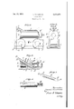
- the improved cutter chain comprises a bit block i of improved design, pivotally connected by transverse pins 2 to side straps 3.
- the cutter chain is of the reversible type and is adapted to cooperate with any suitable form of driving means for driving the same in either of opposite directions.
- Extending longitudinally through the body 5 of the bitblock is a bore 5 of uniform diameter for receiving a cylindrical bit holder 6.
- the bit block body is provided with oppositely inclined bores 1 and 8, while the cylindrical bit holder is traversed by an inclined bore 9, the bore s when in the position shown in Fig. 3 registering with the bore 1.
- the bore 1 opens at the forward end of the block body at the top thereof, while the bore 8 is similarly located at the rear end of the block body.
- Received in the bores 'i and 9 is a cylindrical body It of the cutter bit.
- This cutter bit may be identical in design to that dis closed inthe copending application of one Morris'P. Holmes, Serial No. 658,804, filed Feb. 27,
- the bit is in the form of a cylindrical rod section-having beveled end surfaces it and 42 forming cutting points It at the opposite ends of the cylindrical bit body.
- the bit may be formed from various symmetrically shaped bar stock, and it is not desired to limit the invention tothe particular 'form shown.
- the cutter bit has its points l3, l3 at its opposite ends and at the extremities of elongated faces which are-identic in eumne, lie'in planes forming a dihedral angle, and are individually symmetrical as to both major and minor axial lines.
- the rearward end of the cylindrical holder 6 is provided with a reduced threaded portion M for receiving an adjusting nut l5 acting against the rear face of the bit block body.
- the nut I5 When it is desired to operate the cutter chain in the reverse direction, the nut I5 is loosened and the cutter bit withdrawn from the bores and 9.
- the cylindrical bit holder 6 is then turned through 180 to bring the bore 9 in registry with the oppositely inclined bore 8 in the bit block.
- the cutter bit is then inserted in the bores 8 and 9, and the nut i5 is then again tightened to clamp the bit in operative position.
- the bit holder may be turned end-for-end to bring the bores 8 and 9 into registry, the nut l5 then'acting on theopposite face of the bit block body.
- the bit holder may be provided with a plurality of inclined bores 9, one registering withthe bore 7 and the other registering with the oppositely inclined bore 8 in the bit block, so that readjustment of the bit holder would be unnecessary when reverse operation of the cutter chain is desired.
- bit blocks are arranged in series and connected together by the side straps 3', and different bit blocks are provided with bores which correspond to'the bores l and 8, and whoseaxes are respectively similarly inclined with respect to the axial line of the bore 5, but whichliein pairs in difierent axial planes passing through the axisof bore 5, so that as the cutter chain is driven a kerf is cut in the material acted upon thereby, to a width sufiicient to receive the cutter chain blocks, by the bits in said bores.
- an improved cutter chain is provided,:having an improved bit block and associated bit. holding means for holding the bit in place within theblock.
- the improved cutter chain is of an extremely simple design, the improved' bit blocksockets being formed "by simple'boring operations andthe improved bit holder being formed 'of-a cylindrical piece of bar stock turned into shape, thereby greatly decreasing the cost of manufacture.
- my invention may assume a ment having a cylindrical body receivable in said longitudinal bore, said bit block having a longitudinally-inclined transversely disposed bit receiving opening terminating at its inner end in said longitudinalbore and said bit holding element having a longitudinally-inclined transversely disposed bit receiving opening, said inclined openings when alined adapted to receive the body of a cutter bit, the inner end of the bit terminating within said opening in saidholding element, and means for adjusting said holding element axially in its bore to clamp the bit in position in said inclined bit block opening.
- a cutter chain comprising a bit block having a longitudinal bore, a cutter bit holdingele ment having a cylindrical body receivable in said longitudinal bore, said bit block having a longi- V tudinally-inclined transversely disposed bit receiving opening terminating at its inner end in 'said longitudinal bore and said bit holding element having a longitudinally-inclined transversely disposed bit receiving opening, said inclined openings when alined adapted toreceive the body of a cutter bit.
- means for adjusting said holding element axially in its bore to clamp the bit in position in said inclined bit block opening including an adjustable holding-element-adjusting member and means formed at one end of said bit holding element with which said adjustable member cooperates in effecting axial adjustment of Said holding element.
- a cutter chain comprising a bit block having a longitudinal bore and a relatively inclined bore communicating with said longitudinal bore
- bit holder arranged in said longitudinal bore and having a bore alined withsaid relatively inclined bore, said alined bores adapted to receive 7 a cutter bit, and a cutter bit receivable in said alined bores, said inclined bit block bore terminating at said longitudinal bore and the inner end ,of said bit terminating within the bore in said bit holder.
- a cutter chain comprising a bit block having a longitudinal boreand a relatively inclined bore communicating with said longitudinal bore
- a bit holder arranged in said longitudinal bore and having a bore alined with said-relatively inclined bore, said alined bores adapted to receive a cutter bit, a cutter bit receivable in said alined bores, said inclined bit block bore terminating at said longitudinal .boreand the inner end of said bit terminating..within the bore in said bit holder, and means engageable with said holder for adjusting the latter axially to bring said bit receiving bores slightly out of alinement to hold the cutter bit in position.
- a cutter chain comprising a bit block having a longitudinal bore, oppositely disposed rela tively inclined bit-receiving bores communicat-q ing with said longitudinal bore; and a bit holder mounted in said longitudinal bore and traversed 5 by a bit-receiving opening adapted'to register selectively with either of said relatively inclined bores.
- a cutter chain comprising a'bit block having a longitudinal bore, oppositely disposed relatively inclined bit-receiving bores communicating with said longitudinal bore, a bit holder mounted in said longitudinal bore and traversed by a bit-receiving bore adapted to register selectively with either' of said relatively inclined bores, and means cooperating with said holder for adjusting the same axially to move said registering bores slightly out of registry to hold a cutter bit in'position within one of said relatively inclined bores.
- a reversible cutter chain comprising a bit block, and bit holding means rotatably mounted in said bit block and rotatableinto one position to hold the bit in a position to cut in one direction and into another position to hold the bit in a position to cut in the reverse direction, said bit holding means operative in said first-men tioned positionto hold the bit in position to cut in the first-mentioned direction only, and when in the second-mentioned position to hold the bit in position to cut in the reverse direction only;
- a cutter chain comprising a bit block having a longitudinal bore a cylindrical bit holder receivable in said bit block bore, a bore in said bit block relatively outwardly and forwardly inclined with respect to'and terminating at its inner end in said longitudinal bore, a cutter bit receivable in said inclined'bore and engageable at its inner end with the walls of said longitudinal bore and having an outwardly and forwardly 40 projecting cutting end, the bit being positioned 'in its bore angularly about its longitudinal axis by said engagement of inner end with the .Walls of said longitudinal bore, and means for adjusting said 'bit holder to clamp said bit in position within said inclined bore.
- a cutter chain comprising a bit block having a longitudinal bore, a cylindrical bit holder receivable in said bit block bore, a bore in said bit block relatively outwardly and forwardly inclined with respect to and terminating at its inner end in said longitudinal bore, a double ended cutter bit having pointed cutting ends, said bit receivable in said inclined bore, the inner inactive cutting end of the bit engaging the walls 65 of saidlongitudinal bore, the active cutting end of the bit extending outwardly and forwardly with respect to the bit block, the bit being positioned in its bore angularly'about its longitudinal axis. by engagement of its inner inactive cutting end with the walls of said longitudinal bore, and means. for adjusting said bitholder to clamp said bit in position in saidinclined bore.
- a cutter chain comprising a bit block having a longitudinal bore, oppositely -disposed relatively inclined bit-receivingbores communicating inits here with either of said relatively inclined bores.
Landscapes
- Engineering & Computer Science (AREA)
- Mining & Mineral Resources (AREA)
- Mechanical Engineering (AREA)
- Life Sciences & Earth Sciences (AREA)
- General Life Sciences & Earth Sciences (AREA)
- Geochemistry & Mineralogy (AREA)
- Geology (AREA)
- Earth Drilling (AREA)
Description
Jan. 28, 1936. E M N EJ128331 CUTTER CHAIN Filed June 27, 1953 7 J52 Ue7z%r: 1 [@0725 Ja'wzmond.
Patented Jan. 28, 1936 UNiTED STAT-ES PATENT OFFICE CUTTER CHAIN Massachusetts Application June 2'7, 1933, Serial No. 677,881
Claims.
This invention relates to cutter chains, and more particularly to improvements in cutter chains especially designed for use with coal cutting appliances.
An object of this invention is to provide an improved. cutter chain. Another object is to pro- Vide an improved bit block for a cutter chain and. improved means for holding the cutter bit within the bit block. Stillanother object is to ;provide an improved reversible cutter chain. .These and other objects of the invention will,
. ter bit.
In this illustrative construction, the improved cutter chain comprises a bit block i of improved design, pivotally connected by transverse pins 2 to side straps 3. The cutter chain is of the reversible type and is adapted to cooperate with any suitable form of driving means for driving the same in either of opposite directions. Extending longitudinally through the body 5 of the bitblock is a bore 5 of uniform diameter for receiving a cylindrical bit holder 6. The bit block body is provided with oppositely inclined bores 1 and 8, while the cylindrical bit holder is traversed by an inclined bore 9, the bore s when in the position shown in Fig. 3 registering with the bore 1. The bore 1 opens at the forward end of the block body at the top thereof, while the bore 8 is similarly located at the rear end of the block body. Received in the bores 'i and 9 is a cylindrical body It of the cutter bit. This cutter bit may be identical in design to that dis closed inthe copending application of one Morris'P. Holmes, Serial No. 658,804, filed Feb. 27,
1933, and is in the form of a cylindrical rod section-having beveled end surfaces it and 42 forming cutting points It at the opposite ends of the cylindrical bit body. The bit may be formed from various symmetrically shaped bar stock, and it is not desired to limit the invention tothe particular 'form shown. The cutter bit has its points l3, l3 at its opposite ends and at the extremities of elongated faces which are-identic in eumne, lie'in planes forming a dihedral angle, and are individually symmetrical as to both major and minor axial lines. The rearward end of the cylindrical holder 6 is provided with a reduced threaded portion M for receiving an adjusting nut l5 acting against the rear face of the bit block body.
When. the cutter bit is inserted in the position shown in Fig. 3 and the nut l5 tightened, the bit holder is drawn axially in the rearward direction to rigidly clamp the cutter bit within the opening 7. When the cutting end I3 of the cutting face I2 becomes dull, the nut i5 is loosened, thereby to permit axial release of the cutter bit from the bores 9 and l; and the bit is then turned end-for-end within the bores l and 9, thereby to present a new cutting point, the inclined surface H of the bit at that time presenting the 1 active cutting point. The nut is then again tightened to draw the bores l and 9 slightly out of alinement to clamp the bit against axial displacement from the bore 5. When it is desired to operate the cutter chain in the reverse direction, the nut I5 is loosened and the cutter bit withdrawn from the bores and 9. The cylindrical bit holder 6 is then turned through 180 to bring the bore 9 in registry with the oppositely inclined bore 8 in the bit block. The cutter bit is then inserted in the bores 8 and 9, and the nut i5 is then again tightened to clamp the bit in operative position. In lieu of rotating the bit holder 6 in the manner above described, the bit holder may be turned end-for-end to bring the bores 8 and 9 into registry, the nut l5 then'acting on theopposite face of the bit block body. Also if desired, the bit holder may be provided with a plurality of inclined bores 9, one registering withthe bore 7 and the other registering with the oppositely inclined bore 8 in the bit block, so that readjustment of the bit holder would be unnecessary when reverse operation of the cutter chain is desired. In the improved cutter chain, the bit blocks are arranged in series and connected together by the side straps 3', and different bit blocks are provided with bores which correspond to'the bores l and 8, and whoseaxes are respectively similarly inclined with respect to the axial line of the bore 5, but whichliein pairs in difierent axial planes passing through the axisof bore 5, so that as the cutter chain is driven a kerf is cut in the material acted upon thereby, to a width sufiicient to receive the cutter chain blocks, by the bits in said bores.
As a result of this invention, it will be noted that an improved cutter chain is provided,:having an improved bit block and associated bit. holding means for holding the bit in place within theblock. It will further be noted that the improved cutter chain is of an extremely simple design, the improved' bit blocksockets being formed "by simple'boring operations andthe improved bit holder being formed 'of-a cylindrical piece of bar stock turned into shape, thereby greatly decreasing the cost of manufacture. These and other uses and advantages of the improved cutter chain will be clearly apparent to those skilled in the art. 7
While I have in this application specifically described one form which my invention may assume a ment having a cylindrical body receivable in said longitudinal bore, said bit block having a longitudinally-inclined transversely disposed bit receiving opening terminating at its inner end in said longitudinalbore and said bit holding element having a longitudinally-inclined transversely disposed bit receiving opening, said inclined openings when alined adapted to receive the body of a cutter bit, the inner end of the bit terminating within said opening in saidholding element, and means for adjusting said holding element axially in its bore to clamp the bit in position in said inclined bit block opening.
A cutter chain comprising a bit block having a longitudinal bore, a cutter bit holdingele ment having a cylindrical body receivable in said longitudinal bore, said bit block having a longi- V tudinally-inclined transversely disposed bit receiving opening terminating at its inner end in 'said longitudinal bore and said bit holding element having a longitudinally-inclined transversely disposed bit receiving opening, said inclined openings when alined adapted toreceive the body of a cutter bit. the inner end of the bit terminating within said opening in said holding element, and means for adjusting said holding element axially in its bore to clamp the bit in position in said inclined bit block opening including an adjustable holding-element-adjusting member and means formed at one end of said bit holding element with which said adjustable member cooperates in effecting axial adjustment of Said holding element.
3. A cutter chain comprising a bit block having a longitudinal bore and a relatively inclined bore communicating with said longitudinal bore,
a bit holder arranged in said longitudinal bore and having a bore alined withsaid relatively inclined bore, said alined bores adapted to receive 7 a cutter bit, anda cutter bit receivable in said alined bores, said inclined bit block bore terminating at said longitudinal bore and the inner end ,of said bit terminating within the bore in said bit holder. l.
4. A cutter chain comprising a bit block having a longitudinal boreand a relatively inclined bore communicating with said longitudinal bore,
1 a bit holder arranged in said longitudinal bore and having a bore alined with said-relatively inclined bore, said alined bores adapted to receive a cutter bit, a cutter bit receivable in said alined bores, said inclined bit block bore terminating at said longitudinal .boreand the inner end of said bit terminating..within the bore in said bit holder, and means engageable with said holder for adjusting the latter axially to bring said bit receiving bores slightly out of alinement to hold the cutter bit in position. Q Q
5. A cutter chain comprising a bit block having a longitudinal bore, oppositely disposed rela tively inclined bit-receiving bores communicat-q ing with said longitudinal bore; and a bit holder mounted in said longitudinal bore and traversed 5 by a bit-receiving opening adapted'to register selectively with either of said relatively inclined bores.
6. A cutter chain comprising a'bit block having a longitudinal bore, oppositely disposed relatively inclined bit-receiving bores communicating with said longitudinal bore, a bit holder mounted in said longitudinal bore and traversed by a bit-receiving bore adapted to register selectively with either' of said relatively inclined bores, and means cooperating with said holder for adjusting the same axially to move said registering bores slightly out of registry to hold a cutter bit in'position within one of said relatively inclined bores. a
'7. A reversible cutter chain comprising a bit block, and bit holding means rotatably mounted in said bit block and rotatableinto one position to hold the bit in a position to cut in one direction and into another position to hold the bit in a position to cut in the reverse direction, said bit holding means operative in said first-men tioned positionto hold the bit in position to cut in the first-mentioned direction only, and when in the second-mentioned position to hold the bit in position to cut in the reverse direction only;
8. A cutter chain comprising a bit block having a longitudinal bore a cylindrical bit holder receivable in said bit block bore, a bore in said bit block relatively outwardly and forwardly inclined with respect to'and terminating at its inner end in said longitudinal bore, a cutter bit receivable in said inclined'bore and engageable at its inner end with the walls of said longitudinal bore and having an outwardly and forwardly 40 projecting cutting end, the bit being positioned 'in its bore angularly about its longitudinal axis by said engagement of inner end with the .Walls of said longitudinal bore, and means for adjusting said 'bit holder to clamp said bit in position within said inclined bore.
9. A cutter chain comprising a bit block having a longitudinal bore, a cylindrical bit holder receivable in said bit block bore, a bore in said bit block relatively outwardly and forwardly inclined with respect to and terminating at its inner end in said longitudinal bore, a double ended cutter bit having pointed cutting ends, said bit receivable in said inclined bore, the inner inactive cutting end of the bit engaging the walls 65 of saidlongitudinal bore, the active cutting end of the bit extending outwardly and forwardly with respect to the bit block, the bit being positioned in its bore angularly'about its longitudinal axis. by engagement of its inner inactive cutting end with the walls of said longitudinal bore, and means. for adjusting said bitholder to clamp said bit in position in saidinclined bore.
10, A cutter chain comprising a bit block having a longitudinal bore, oppositely -disposed relatively inclined bit-receivingbores communicating inits here with either of said relatively inclined bores. V
' LEON E. SIMMONS.
Priority Applications (1)
| Application Number | Priority Date | Filing Date | Title |
|---|---|---|---|
| US677881A US2028811A (en) | 1933-06-27 | 1933-06-27 | Cutter chain |
Applications Claiming Priority (1)
| Application Number | Priority Date | Filing Date | Title |
|---|---|---|---|
| US677881A US2028811A (en) | 1933-06-27 | 1933-06-27 | Cutter chain |
Publications (1)
| Publication Number | Publication Date |
|---|---|
| US2028811A true US2028811A (en) | 1936-01-28 |
Family
ID=24720470
Family Applications (1)
| Application Number | Title | Priority Date | Filing Date |
|---|---|---|---|
| US677881A Expired - Lifetime US2028811A (en) | 1933-06-27 | 1933-06-27 | Cutter chain |
Country Status (1)
| Country | Link |
|---|---|
| US (1) | US2028811A (en) |
Cited By (1)
| Publication number | Priority date | Publication date | Assignee | Title |
|---|---|---|---|---|
| US4650254A (en) * | 1983-12-14 | 1987-03-17 | Joy Manufacturing Company | Bit holder |
-
1933
- 1933-06-27 US US677881A patent/US2028811A/en not_active Expired - Lifetime
Cited By (1)
| Publication number | Priority date | Publication date | Assignee | Title |
|---|---|---|---|---|
| US4650254A (en) * | 1983-12-14 | 1987-03-17 | Joy Manufacturing Company | Bit holder |
Similar Documents
| Publication | Publication Date | Title |
|---|---|---|
| US1244785A (en) | Mining-machine chain. | |
| US2645844A (en) | Toolholder | |
| US2529157A (en) | Routing tool | |
| US2289464A (en) | Kerf cutting device | |
| US2028811A (en) | Cutter chain | |
| US1415379A (en) | Tool holder | |
| US2418734A (en) | Tool holder | |
| US2020215A (en) | Cutter chain | |
| US2123213A (en) | Cutter chain | |
| US2183581A (en) | Cutter chain | |
| US2722410A (en) | Mining cutter bit block | |
| US2348061A (en) | Cutter chain | |
| US2018674A (en) | Metal cutting or reaming device | |
| GB672039A (en) | Improvements in or relating to tools for lathes, planing machines, and similar machine tools | |
| US1415237A (en) | Cutting tool and holder | |
| US2272692A (en) | Cutter chain | |
| US2039747A (en) | Bit block | |
| US2227737A (en) | Cutter chain | |
| US2039416A (en) | Cutter chain | |
| US1926047A (en) | Cutter chain | |
| US1999193A (en) | Cutter chain | |
| US2263589A (en) | Cutter chain | |
| US2644679A (en) | Cutter chain | |
| GB307786A (en) | ||
| US2451246A (en) | Tool bit and holder therefor |