US2024948A - Method of and apparatus for signaling - Google Patents
Method of and apparatus for signaling Download PDFInfo
- Publication number
- US2024948A US2024948A US175756A US17575627A US2024948A US 2024948 A US2024948 A US 2024948A US 175756 A US175756 A US 175756A US 17575627 A US17575627 A US 17575627A US 2024948 A US2024948 A US 2024948A
- Authority
- US
- United States
- Prior art keywords
- station
- switch
- signal
- solenoid
- main
- Prior art date
- Legal status (The legal status is an assumption and is not a legal conclusion. Google has not performed a legal analysis and makes no representation as to the accuracy of the status listed.)
- Expired - Lifetime
Links
- 238000000034 method Methods 0.000 title description 13
- 230000011664 signaling Effects 0.000 title description 13
- 230000008859 change Effects 0.000 description 32
- 230000001276 controlling effect Effects 0.000 description 13
- 230000000737 periodic effect Effects 0.000 description 11
- 238000010586 diagram Methods 0.000 description 8
- 230000004044 response Effects 0.000 description 7
- 230000007246 mechanism Effects 0.000 description 4
- 230000005540 biological transmission Effects 0.000 description 2
- 230000001143 conditioned effect Effects 0.000 description 2
- 239000003471 mutagenic agent Substances 0.000 description 2
- 230000001105 regulatory effect Effects 0.000 description 2
- TVEXGJYMHHTVKP-UHFFFAOYSA-N 6-oxabicyclo[3.2.1]oct-3-en-7-one Chemical compound C1C2C(=O)OC1C=CC2 TVEXGJYMHHTVKP-UHFFFAOYSA-N 0.000 description 1
- 241000518994 Conta Species 0.000 description 1
- 101100001670 Emericella variicolor andE gene Proteins 0.000 description 1
- 230000009471 action Effects 0.000 description 1
- 150000001768 cations Chemical class 0.000 description 1
- 239000004020 conductor Substances 0.000 description 1
- 210000004907 gland Anatomy 0.000 description 1
- 239000011521 glass Substances 0.000 description 1
- 238000009413 insulation Methods 0.000 description 1
- 230000004048 modification Effects 0.000 description 1
- 238000012986 modification Methods 0.000 description 1
- 238000009877 rendering Methods 0.000 description 1
- ACWBQPMHZXGDFX-QFIPXVFZSA-N valsartan Chemical class C1=CC(CN(C(=O)CCCC)[C@@H](C(C)C)C(O)=O)=CC=C1C1=CC=CC=C1C1=NN=NN1 ACWBQPMHZXGDFX-QFIPXVFZSA-N 0.000 description 1
- 238000004804 winding Methods 0.000 description 1
Images
Classifications
-
- B—PERFORMING OPERATIONS; TRANSPORTING
- B61—RAILWAYS
- B61L—GUIDING RAILWAY TRAFFIC; ENSURING THE SAFETY OF RAILWAY TRAFFIC
- B61L27/00—Central railway traffic control systems; Trackside control; Communication systems specially adapted therefor
- B61L27/20—Trackside control of safe travel of vehicle or train, e.g. braking curve calculation
Definitions
- the present invention relates to method and apparatus for the control of railroad, highway or other trafi'ic to give signals to indicate that a particular way is open or closed to passage and to a method of operation of such apparatus.
- the invention will be exampled in apparatus if; illustrated diagrammatically in the drawings and herein described for the purpose of directing road .or railroad traffic in successive waves.
- the waves will consist of single trains with clear gaps between to insure safety.
- the waves can include a number of vehicles and the gaps utilized to permit the passage of cross traffic.
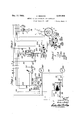
- Fig. l is a diagram of connections and apparatus used in one of the signal control stations of my invention.
- Figs. 2, 3, and 6 show diagrams of connections and apparatus used in the signal stations oper- 30 ated by the control station of Fig. 1.
- Fig. 4 is a diagram of the apparatus used to change the signal.
- Fig. shows a diagram of the signal actuating means.
- Fig. 1 shows a main control station and apparatus, and connected thereto is a signal station and apparatus shown in Fig. 2, to which is connected another similar signal station illustrated in Fig. 3.
- the control station is at any suitable 45 place such as at a point along a highway from any other place.
- the signal stations are placed which traffic conditions can be observed or at at intervals along a traflic route preferably at street intersections and at distances apart to suit 50 the traffic requirements and conditions of any particular route or highway.
- the mains l and 2 serve to connect to a source of electrical energy either of direct or alternating current and can extend unbroken as far through- 56 out the system as the source designated is used.
- an electric lamp 4 connected across mains l and 2 and having mounted thereab-out a vertical four sided screen, or lantern element, 5 comprising the oppositely mounted green glass panes 8 and the 5 alternate red panes l8.
- a Fresnal lens l2 having vertical light concentrating ribs and having a motor It for rotating it 10 about said lamp 4, which motor is also connected across mains l and 2.
- a relay line 20 through the switch 2! and the commutator 22, to the relay solenoid 24 at the signal station illus- 'trated in Fig. 2 and thence to main i.
- at the main station enables the line 26 to be energized through the commutator 22, or to be directly connected to main 2, or to be entirely 2Q notch engagement with each other, as shown in Fig. 1.
- C'ommutator 22 is connected to main 2 on one side through the switch 2
- the other side of the commutator is connected to relay line through a slidable brush 45, 30 which can be placed directly opposite brush 48 to give a continuous flow of current to line 29, or can be fixed at the opposite end of commutator 22 from brush 48.
- a slidable brush 45, 30 which can be placed directly opposite brush 48 to give a continuous flow of current to line 29, or can be fixed at the opposite end of commutator 22 from brush 48.
- no current will flow through the commutator, at all intermediate positions of brush 46 the relative period of current flow and interruption thereof will depend on the relative amounts of conducting surface of the cylinder 42 and insulation surface of the cylinder 44, which brush as traverses, and the speed of rotation of the commutator.
- the commutator is driven by a motor 50 connected to brush .8, and to line I by a connection 56.
- the field winding of motor 5%) is provided with a rheostat 58 to regulate its speed.
- a wire 60 connects from main 2 through a two contact relay switch lever 62 mounted in operable relation to relay solenoid 24 which when energized by line 20 is operable to move lever 62 to contact with a contact point 64 to which is connected one end of a solenoid 66 the other end of which is connected to a contact point 10.
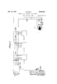
- the solenoid 66 is shown diagrammatically in Fig. 2. It constitutes one of a group of three magnets used to shift the signal position of the lantern element, or screen 6, as will be understood from Fig. 4 in which these magnets are marked 66, 16, and I02. As further indicated in Fig. 4, each succeeding signal station is provided with a like group of magnets, used for the same purpose.
- a spring 12 opposed to' solenoid 24 tends to move lever 62 into contact with a point 14 which is connected to one end of solenoid 16 which at its other end connects a contact point 80.
- a relay switch lever 82 is mounted in operable relation to points 10 and 80 and has a spring 84 which tends to move it to contact with point 10.
- a solenoid 90 connected on one side through a wire 92 to main I and on the other side to main 2 through .a wire 94, armature operated switch 96, and wire 98, serves when energized to oppose spring 84 and to move lever 82 into contact with contact 80.
- the switch 96 is operated by an armature 260, shown in Figs. 4 and 5 and is described more fully below.
- switch lever 82 From switch lever 82 connection is made to one side of a solenoid I02 the other side of which connects to two parallel contact points I04 and I06.
- a switch lever I08 in operable relation to point I04 connects through a wire I ID to main I and a switch lever H2 in operable relation to 7 point I06 connects through a wire I I4 to wire I I0.
- a solenoid I20 connected in parallel with solenoid I02 serves when energized to move lever H2 into contact with its point I06 and .
- a solenoid I22 connects from main I through wire H0 011 one side and on its other side by a wire I24 to a relay main I26. Solenoid I22 serves when energized to move lever I08 into contact with its point I 04.
- Relay main I26 extends along the whole series or along a given series of signal stations and to the main station where it connects to a contact point I28 which is spaced apart from a cooperating point I30 which connects through a wire I32 to' main 2.
- a gear I34 carries a brush I 36 mounted to move across and connect contacts I28 and I30 for a given portion of a rotation of said gear I34.
- a motor I38 connected to main 2 through a wire I40, a switch I42, and a wire I44 and to the main I through a wire I46 and wire 56 serves to rotate said gear I34 and brush I36 at a given rate of speed and the rheostat I48 serves to regulate the speed of motor I38v
- a switch I49 is provided for the purpose of short circuiting points I28 and I30 or for the manual control of the circuit thereof.
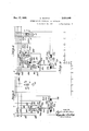
- a wire I50 connects from a point between switch 96 and solenoid 90 to the solenoid I52 at the next signal station, herein illustrated in Fig. 3, and therefrom through a wire I 54 to main I.
- a wire I connects from main 2 through a two contact relay switch lever I62 mounted in operable relation to relay solenoid I52 which when energized is operable to move lever I62 to contact with a point I64 to which is connected 7 one end of a solenoid I66, the other end of which is connected to a-point I19.
- a spring I12 opposed to solenoid I52 tends to move lever I62 into one end of a solenoid I16 which connects at its A relay switch lever I 82 is mounted in operable relation to points 7 I10 and I and has a spring I 84 which tends to move it to contact with point I10.
- a solenoid I connected on one side through a wire I92 to main I and on the other side through a wire I94, armature operated switch I96, and wire I98 to main 2 serves when energized to oppose spring I84 and to move lever I82 into contact with point I80.
- solenoid 202 which is a counterpart of solenoid I02 of the station of Fig. 2.
- Other parts and wires connected with solenoid 202 and numbered from 204 to 224 and counterparts of similar parts and wires number I94 to I24 of Fig. 2 connect from solenoid 202 to said main I and to said relay main I26. Said parts and counterparts have similar relations and function in the operation of the system and therefore further description will not be made of the counterparts.
- a wire 250 connects from wire I94 at the station of Fig. 3 and extends to the next subsequent or to another subsequent signal station where it connects to a solenoid corresponding to solenoids 24 and I52 of the stations of Figs. 2 and 3, respectively.
- switch 96 (I96) is connected mechanically to an actuating armature 260 (360) which is in operative relation to solenods 66 (I66), 16 (I16) and I02 (202) which are mounted thereabout in a horizontal plane and at 90 apart, as shown in Fig. 4.
- solenoids 66 and I82 are simultaneously energized armature 260 is drawn to a point there-between and switch 96 is closed, by the mechanical connections indicated in Fig.
- each one of the lamps 4, 4 will be illuminated and each of the Fresnal lenses I2 will be constantly rotated about its axis by its respective motor I4.
- the red screens I0, I0 will be facing in a given direction for example, in the same direction along a given thoroughfare and trafilc will be stopped.
- the purpose is to send successive and alternate bands or strips of red and green light along the thoroughfare to permit traffic to move along with and in the area of the green .strips'and at the same time to permit cross traffic to pass at those places at which red light faces the thoroughfare.
- solenoid .24 When commutator 22 arrives at the open circuit phase solenoid .24 will be deenergized and spring 12 will move lever 62 into contact with point I4 to prepare the station of .Fig. 2 for a --Qhange from green to red which will occur upon the next impulse made upon closing circuit by conta q .3
- solenoids I6 and I02 are energized and armature 260 moved from the position between solenoids 66 and I02 to a position between solenoids I6 and I02 thereby moving the light screens to change the green to red and also opening switch 96 to deenergize solenoids and I52.
- the deenergizing of solenoid 90 permits spring 84 to move switch lever 82 to contact with point I0 and thereby make the first preparatory step in the subsequent change of the station ofFig. 2 from the red back .again to the green light along the given thoroughpulse along main i 26 made by the closing of that main by contactor I36. Following successive changes will be made in steps along the system upon each impulse sent through main I26 as hereinbefore described.
- each opening of the control circuit 20 by commutator 22 will start a .waveof red light along the thoroughfare and this wave will continue to move along the thoroughfare.
- a green wave will be started after the red upon the closing of circuit 20 by the commutator 22 and the back end of the red wave will change to green in successive steps, each step being instituted by each successive impulse sent through said main I26 by said contactor I36.
- the length of the alternate strips of green and red signals will be determined by the length of time commutator 22 is on or on. And the time relation can be changedby sliding brush 46 to any desired position on commutator 22.
- the rate of make and break by contactor I36 determines the time 111* solenoid) is energized the solenoid I20 (or a corresponding solenoid) is energized and switch lever H2 is closed to point Hi6 thereby providing a circuit in parallel to that of switch I08, and provides that the circuit of solenoid I02 is not opened until .said armature 260 completes its movement to change the signal from one color to another.
- the deenergization of solenoid I20 and the opening of switch II2 is accomplished when armature 260 finishes its movement and either opens or closes said switch 96 in a manner above P described.
- the waves or strips of light of a given color can be made any given length, determined by the number of impulses which the contactor I36 sends out during a given period either of contact or of It also insures that a change of make to break or of break to make by commutator 22 starts a new wave of a given color from the starting end of the system. Further, regulation ofthe time between changes can be accomplished by regulating the rate of speed of rotation of said commutator 22; and this can be done, of course, either with or without changing the relative lengths of the red and. green waves. 7
- the system can be hand operated or can be operated or controlled partly automatically and partly by hand by using either or both of the said switches 2
- I49 is used, in place of their respective automatic parts which are respectively com mutator 22 and contactor I36.
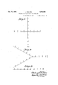
- the system also can be regulated or controlled to have the order of change of light reversed so that a wave travels in the direction opposite to the series of stations similar to that of Fig. l and also of the following apparatus which is added to each of the signal stations such as those of Figs. 2 and 3, together with the lead or main 388 which connects at the main station of Fig. 1 and extends to each of the signal stations of the system, such for example as those of Figs. 2 and 3, main 380 connecting at the main station of Fig. 1 through the single poleswitch 382 to main 2 and on the other side extends throughout the length of the system to the additional control station at the other end.
- Fig. 7 illustrates somewhat diagrammatically a system having at M a main master station such as that of Fig.
- station A which is a first signal station next to the main master station
- station B which is any intermediate signal station
- station N which is the last signal station away from the main master station and beyond which is connected a motor 459 to mains I and 389, and a commutator 422 which is driven by motor 458 and is connected across said main 380 on one side and to the lead 359 which corresponds to lead 26 of Fig. 2 and to lead 259 of Fig. 6.
- line 380 connects through a solenoid 384 or a corresponding one to main I.
- Solenoid 384 is operable when energized to move a switch lever 388 against the action of a tension spring 398.
- Lever 388 carries two contact points 392 and 394 which are insulated from each other and which when moved by spring 399 contact with the points 396 and 398, respectively.
- solenoid 384 points 392 and 394,'respec-.
- motor 450 beyond station N of Fig. 7 isenergized and current is passed from main 380 intermittently through commutator 422 to the solenoid corresponding to solenoid I52 of Fig. 6 whereby the apparatus of the station is set prepared for a signal change.
- a similar switch 424 which at station A is left open because it will not be needed inasmuch as it is used at the other stations for relaying a preparatory signal backwardly of the series of stations; and a switch 426 in the lead between contacts 398 and 498 is left open at station N inasmuch as connection between these contacts is needed only at station A and intermediate station up to station N to relay preparatory signals forwardly through a series of stations.
- switches 424 and 426 are in the form of jumpers or leads between the respective contacts, and these jumpers are left out at the proper stations, that between 398 and 489 at station A and between 392 and 492 at station N.
- impulses starting at other control stations by commutator 422 can be sent in a manner already described above for the control station of Fig. l for the purpose of originating successive alternate bands or waves of red and green lights which move in the direction opposite to that in which first station sends them and traffic can be controlled to move in waves in said opposite direction, with time intervals between waves to permit passage of cross trafiic.
- the system above described can also be used for turning the same color signal throughout the whole system at once by closing switch I49 to keep closed relay I22 at station of Fig. 2 and the relays at the other stations which correspond to it.
- the first signal station will change color and each of the following stations will operate immediately upon the change of the preceding station.
- the interval of time taken for the operation of each station will be practically instantaneous, especially as regards adjacent stations. tion the traffic directedcan proceed in both directions at once in the thoroughfare on which the system is used.
- the wave control of traflic above described is best adapted for one way trafiic, except where intervals between change between consecutive stations is not'short and the waves of light are comparatively long in which case the trafiic can pass in both directions with suitable time intervals for passage of cross traflic without causing confusion.
- the apparatusabove described can be used for directing traflic on a multiplicity of thoroughfares at the same time.
- a series of signals E-,.E ar- With this manner of opera-' 1 rangedalong a cross street are connected in parallel with a signal station E positioned at a corner of a main thoroughfare and the operation of said stations E, E will be simultaneous and like that 5 of said station E whereby cross traffic is directed synchronously with the traffic in the -main thoroughfare.
- FIG. 9 a main thoroughfare along'which are arranged stations A, B, C, D, E divides into two 10 other diverging or conveying thoroughfares on each of which the system is continued in branches which are in parallel with each whereby the stations F and F, G and G, etc., will operate simultaneously in pairs to control trafiic passing thereby to or from said main thoroughfare.
- Fig. 10 is illustrated in diagram a series of stations C, C, C, along the same thoroughfare which are connected to operate simultaneously to give the same signal at the same time whereby a congestion of traffic, for example, at a given portion or zone of a given thoroughfare is taken care of as when a confluence of traffic enters the main thoroughfare, continues on it for a given distance, and then passes on by cross thoroughfares leaving the state of traffic on the subsequent portion somewhat like that which is on the portion before said congested portion is reached.
- a congestion of traffic for example, at a given portion or zone of a given thoroughfare is taken care of as when a confluence of traffic enters the main thoroughfare, continues on it for a given distance, and then passes on by cross thoroughfares leaving the state of traffic on the subsequent portion somewhat like that which is on the portion before said congested portion is reached.
- Fig. 11 is illustrated in diagram a thoroughfare having sudden turns on account of which it is zo desirable to slow up traific for a portion of the thoroughfare.
- This control is secured by'spaci'ng the signal stations closer together at the corners andbetween the corners wherea-t the trailic waves will be shorter and whereby signals permitting ad- -"vance will be given at shorter distance alongthe route.”
- the driver of vehicles at the dangerous portions of the thoroughfare will be held in bounds and speed b'etween signal stations will be reduced. 40"
- the time interval betweenchanges in signals for adjacent stations is the same between stations which are close to-" gether as they are between stations that-are'further apart.
- each of said magnets being open, a two point relay switch for making connection to one side of either ofsaid magnets, a second two point relay switch for making connection to the other side of either of said magnets, means tend- 5' net, a pair of current source mains-between con- 15' secutive signal stations, connection from first said relay coil through a third switch to said mains, mechanical connection between said armature and said third switch whereby in one signaling movement or position it closes and in'go the other position it opens said third switch,
- a connection from a point between said first relay coil and said third switch to the second said relay coil of another signal station connection from second said two point relay switch 15 to one of said current mains, connection from first said two point relay switch through athird relay coil and thence through a fourth switch which is a relay switch to the other of "said mains, a fifth switch which is a relay switch in 30' shunt with said fourth switch and in operable relation with said third relay coil and adapted to be held closed thereby, means tending to hold said fifth switch open, a fourth relay coil in operable relation to said fourth switch and adapted when 35' energized to close it, means tending to open said fourth switch, a third main extending along'said series of stations, said fourth relay coil being connected acrosssaid first and third mains, means for intermittently energizing the second 40 relay coil of the first station of the series, and means for intermittently connecting said third main to said second main.
- a central control station a plurality of signal stations having display signals, a circuit means connecting the control station to each of said signals, a similar second circuit means, mechanism at the control fecting the flow of current over the second circuit means, signal changing means responsive to perirate of actuation of individual signal indications 'odic control over the first circuit means for changing the display of said signals successively, one signal, when changing, having means rendering the succeeding signal responsive to the signal changing means, and means responsive to each periodic control over the second circuit means, for establishing a condition for a second change of display by the third named means for the first changed signal of the successively changed signals whereby waves ofdisplay signals are obtained.
- a system as in claim 3 including means at the control station for varying the time between the periodic operations of the said first mechanism for controlling the number of signals in a wave.
- a system as in claim 3 including means at the control station for varying the time between the periodic operations of the said second mechanism for controlling the time between changes of the display at each signal.
- the method of controlling from a central station the display signals at a plurality of signal units each of which has one of at least two different indications continually displayed, and for which preparation must be made for change of indication before a change can be accomplished which comprises sending an operating manifestation from the central station to each of said signal units at periodic intervals, in response to one of said manifestations at a first unit changing-the indication thereat and preparing a second signal unit to change its indication, in response to the next succeeding manifestation changing the indication at said second station and preparing a third signal unit 10 to change its display, and so on; at intervals greater than the first said intervals preparing the first said station to again change its indication, and at the manifestation following the last said preparation, restarting the operations due to the first said manifestation.
- the method of controlling from a central station the display signals at a plurality of signal units each of which has one of at least two different indications continually displayed, and for which preparation must be made for change of indication before a change can be accomplished which comprises sending an operating manifestation from the central station to each of said signal units at periodic intervals, in response to one of said manifestations at a first unit changing the indication thereat and preparing a second signal unit to change its indi- 55 cation, in response to the next succeeding manifestation changing the indication at said second station and preparing a third signal unit to change its display, and so on; at intervals not less than the first said intervals preparing the first said station to again change its indication, and at the manifestation following the last said preparation, restarting the operations due to the first said manifestation.
- a traific control signaling system comprising a control station and a succession of signals spaced along a highway, and connected by a common supply circuit to the signals, each of said signals having stop and go indications, means at each station which, when conditioned and then operated, changes the display of said signals from one exhibition of said indication to the other, said system also including a plurality of independent periodic current flow controlling means located at said central station, means connected to each of said signals to render the first named means operative in response to a periodic flow of current from one of said controlling, means to change said signal display as aforesaid, other means at each signal operative upon a change of signal display as aforesaid to condition the first said means of the adjacent signal in the succession for similar operation by said one controlling means, and means at the first of said stations operated in response to a periodic flow of current from another of said controlling means to condition first said means at the first signal of said succession whereby the time of display of each indication is deter mined.
- each station including signal means giving stop and go indications, transmission line means connecting the control station and the 15 signal stations, means cooperating with said transmission line means and said signals to cause a succession of waves of stop indications to travel along said line of trafiic alternating with a succession of go indications, including a single 20 adjusting means at the central station for solely determining the time of display of the stop and go indications at each station without aifecting the rate of progression, and a second single adjusting means at the control station for solely 25 determining the rate of progression of the Waves without affecting the said times of display.
Landscapes
- Engineering & Computer Science (AREA)
- Mechanical Engineering (AREA)
- Train Traffic Observation, Control, And Security (AREA)
Description
Dec. 17, 1935. E REG-1N 2,024,948
METHOD OF AND APPARATUS FOR SIGNALING Filed March 16, 1927 4 Sheets-Sheet 1 QONN :aza
v INVENTOR HIS ATTORNEYS Dec. 17, 1935. E. RECHTIN METHOD OF AND APPARATUS FOR SIGNALING Filed March 16, 1927 4 Sheets-Sheet 2 M M M m m w w. W hm V. N 6 N RN 53 M an V3 2 av mm wfi i a m *N. Mu I N i l AN 11 Q Q wmfi w W" mm Mr I! E: W M .m x n. I r Ni V ,Jmwm w m 3% 2 m Q. Q Q U a IR @wl n n Q n w J v4 .QNN w n A K J J 7N fl mm w n Dec. 17, 1935. E. RECHTIN I 2,924,948
METHOD OF AND APPARATUS FOR SIGNALING Filed March 16, 1927 4 Sheets-Sheet 3 s'rAfioNN sTATldN B INVENTOR Dec. 17, 1935., E. RECHTIN 2,024,943
v METHOD OF AND APPARATUS FOR SIGNALING Filed March 16, 1927 4 Sheets-Sheet 4 HIS ATTORNEY Patented Dec. 17, 1935 UNITED STATES METHOD OF AND APPARATUS FOR SIGNALING Eberhardt Rechtin, East Orange, N. J., assignor to George G. Raymond, Weehawken, N. J.
Application March 16, 1927, Serial N0. 175,756
13 Claims.
The present invention relates to method and apparatus for the control of railroad, highway or other trafi'ic to give signals to indicate that a particular way is open or closed to passage and to a method of operation of such apparatus.
Various objects and advantages of the invention will be obvious from the following description of a new and useful apparatus embodying the invention and of a varying or alternate form 10 thereof and from the drawings; and the invention also consists of the apparatus, parts, and combinations and methods set forth in the claims.
The invention will be exampled in apparatus if; illustrated diagrammatically in the drawings and herein described for the purpose of directing road .or railroad traffic in successive waves. On railroads the waves will consist of single trains with clear gaps between to insure safety. In highway 20 traffic the waves can include a number of vehicles and the gaps utilized to permit the passage of cross traffic.
In the drawings are shown diagrams of apparatus illustrating the invention.
25 Fig. l is a diagram of connections and apparatus used in one of the signal control stations of my invention.
Figs. 2, 3, and 6 show diagrams of connections and apparatus used in the signal stations oper- 30 ated by the control station of Fig. 1.
Fig. 4 is a diagram of the apparatus used to change the signal.
Fig. shows a diagram of the signal actuating means.
35 Figs. 7, 8, 9, 10, and 11 show diagrams of modifications of the invention.
In the system of electrical distribution and signaling apparatus shown diagrammatically in Figs. 1, 2, and 3 for illustrating the invention,
40 Fig. 1 shows a main control station and apparatus, and connected thereto is a signal station and apparatus shown in Fig. 2, to which is connected another similar signal station illustrated in Fig. 3. The control station is at any suitable 45 place such as at a point along a highway from any other place. The signal stations are placed which traffic conditions can be observed or at at intervals along a traflic route preferably at street intersections and at distances apart to suit 50 the traffic requirements and conditions of any particular route or highway. In the drawings the mains l and 2 serve to connect to a source of electrical energy either of direct or alternating current and can extend unbroken as far through- 56 out the system as the source designated is used.
At each of the signal stations is connected an electric lamp 4 connected across mains l and 2 and having mounted thereab-out a vertical four sided screen, or lantern element, 5 comprising the oppositely mounted green glass panes 8 and the 5 alternate red panes l8. Around screen 6 and about lamp 4 there is mounted, in the preferred form of this embodiment of the invention, a Fresnal lens l2 having vertical light concentrating ribs and having a motor It for rotating it 10 about said lamp 4, which motor is also connected across mains l and 2.
From main 2 at the main control station illustrated in Fig. 1 there is connected a relay line 20 through the switch 2! and the commutator 22, to the relay solenoid 24 at the signal station illus- 'trated in Fig. 2 and thence to main i. The switch 2| at the main station enables the line 26 to be energized through the commutator 22, or to be directly connected to main 2, or to be entirely 2Q notch engagement with each other, as shown in Fig. 1. C'ommutator 22 is connected to main 2 on one side through the switch 2| and the brush 48. The other side of the commutator is connected to relay line through a slidable brush 45, 30 which can be placed directly opposite brush 48 to give a continuous flow of current to line 29, or can be fixed at the opposite end of commutator 22 from brush 48. In the last named position no current will flow through the commutator, at all intermediate positions of brush 46 the relative period of current flow and interruption thereof will depend on the relative amounts of conducting surface of the cylinder 42 and insulation surface of the cylinder 44, which brush as traverses, and the speed of rotation of the commutator. The commutator is driven by a motor 50 connected to brush .8, and to line I by a connection 56. The field winding of motor 5%) is provided with a rheostat 58 to regulate its speed.
At the signal station of Fig. 2 a wire 60 connects from main 2 through a two contact relay switch lever 62 mounted in operable relation to relay solenoid 24 which when energized by line 20 is operable to move lever 62 to contact with a contact point 64 to which is connected one end of a solenoid 66 the other end of which is connected to a contact point 10. The solenoid 66 is shown diagrammatically in Fig. 2. It constitutes one of a group of three magnets used to shift the signal position of the lantern element, or screen 6, as will be understood from Fig. 4 in which these magnets are marked 66, 16, and I02. As further indicated in Fig. 4, each succeeding signal station is provided with a like group of magnets, used for the same purpose.
A spring 12 opposed to' solenoid 24 tends to move lever 62 into contact with a point 14 which is connected to one end of solenoid 16 which at its other end connects a contact point 80. A relay switch lever 82 is mounted in operable relation to points 10 and 80 and has a spring 84 which tends to move it to contact with point 10. A solenoid 90 connected on one side through a wire 92 to main I and on the other side to main 2 through .a wire 94, armature operated switch 96, and wire 98, serves when energized to oppose spring 84 and to move lever 82 into contact with contact 80. The switch 96 is operated by an armature 260, shown in Figs. 4 and 5 and is described more fully below.
From switch lever 82 connection is made to one side of a solenoid I02 the other side of which connects to two parallel contact points I04 and I06. A switch lever I08 in operable relation to point I04 connects through a wire I ID to main I and a switch lever H2 in operable relation to 7 point I06 connects through a wire I I4 to wire I I0.
Springs H6 and II 8 respectively, tend to hold levers I08 and H2 from contact withtheir respective points I04 and I06. A solenoid I20 connected in parallel with solenoid I02 (it can be in series) serves when energized to move lever H2 into contact with its point I06 and .a solenoid I22 connects from main I through wire H0 011 one side and on its other side by a wire I24 to a relay main I26. Solenoid I22 serves when energized to move lever I08 into contact with its point I 04. Relay main I26 extends along the whole series or along a given series of signal stations and to the main station where it connects to a contact point I28 which is spaced apart from a cooperating point I30 which connects through a wire I32 to' main 2. A gear I34 carries a brush I 36 mounted to move across and connect contacts I28 and I30 for a given portion of a rotation of said gear I34. A motor I38 connected to main 2 through a wire I40, a switch I42, and a wire I44 and to the main I through a wire I46 and wire 56 serves to rotate said gear I34 and brush I36 at a given rate of speed and the rheostat I48 serves to regulate the speed of motor I38v A switch I49 is provided for the purpose of short circuiting points I28 and I30 or for the manual control of the circuit thereof.
Referring to Figs. 2 and 3, a wire I50 connects from a point between switch 96 and solenoid 90 to the solenoid I52 at the next signal station, herein illustrated in Fig. 3, and therefrom through a wire I 54 to main I. At the signal station shown in Fig. 3, a wire I connects from main 2 through a two contact relay switch lever I62 mounted in operable relation to relay solenoid I52 which when energized is operable to move lever I62 to contact with a point I64 to which is connected 7 one end of a solenoid I66, the other end of which is connected to a-point I19. A spring I12 opposed to solenoid I52 tends to move lever I62 into one end ofa solenoid I16 which connects at its A relay switch lever I 82 is mounted in operable relation to points 7 I10 and I and has a spring I 84 which tends to move it to contact with point I10. A solenoid I connected on one side through a wire I92 to main I and on the other side through a wire I94, armature operated switch I96, and wire I98 to main 2, serves when energized to oppose spring I84 and to move lever I82 into contact with point I80.
From switch lever I82 connection is made to a solenoid 202 which is a counterpart of solenoid I02 of the station of Fig. 2. Other parts and wires connected with solenoid 202 and numbered from 204 to 224 and counterparts of similar parts and wires number I94 to I24 of Fig. 2 connect from solenoid 202 to said main I and to said relay main I26. Said parts and counterparts have similar relations and function in the operation of the system and therefore further description will not be made of the counterparts. A wire 250 connects from wire I94 at the station of Fig. 3 and extends to the next subsequent or to another subsequent signal station where it connects to a solenoid corresponding to solenoids 24 and I52 of the stations of Figs. 2 and 3, respectively.
Referring to Figs. 2, 3, 4, and 5 switch 96 (I96) is connected mechanically to an actuating armature 260 (360) which is in operative relation to solenods 66 (I66), 16 (I16) and I02 (202) which are mounted thereabout in a horizontal plane and at 90 apart, as shown in Fig. 4. When solenoids 66 and I82 are simultaneously energized armature 260 is drawn to a point there-between and switch 96 is closed, by the mechanical connections indicated in Fig. 2 between armature 260 and the switch 96, and thereafter when solenoids 16 and I02 are energized and solenoid 66 deenergized armature 260 is moved through 90 to a position between solenoids 16 and I02 and switch 96 is opened. Into the vertical shaft 262 fixedto armature 260 is mounted a screen 6 which is thereby caused to be rotated at different times to positions 90 apart. For purposes of illustration let it be considered that when solenoids 66 and I02 are energized the green screen faces a given direction and when the solenoids 16 and I02 are energized the red screen faces the given direction.
In the use and operation of the apparatus and system above described with mains I and 2 connected to a source of electric energy, either alternating or direct current, each one of the lamps 4, 4 will be illuminated and each of the Fresnal lenses I2 will be constantly rotated about its axis by its respective motor I4. With the operating circuit and apparatus of Fig. 1 and the signal station apparatus of Figs. 2 and 3 in the positions and relations as shown in the drawings the red screens I0, I0 will be facing in a given direction for example, in the same direction along a given thoroughfare and trafilc will be stopped. At the same time motors 50 and I38 are in operation and current will flow from main 2 through wire 20, switch 2I brush 48, commutator 22, brush 46 to the main part of wire 20, and thence to solenoid 24 at the signal station of Fig. 2 and to the other main I whereby solenoid 24 is energized and lever 62 is actuated to be moved into mutator 22 makes and breaks contact for inter- P vals of minutes, say the make for four minutes and the break for two minutes.
When commutator 22 is in circuit and contactor I36 closes contact between points I28 and I30 current flows from main 2 along relay main I26 to the solenoid I22;at each-of the si-gnal stations. .A t -s at on- Fig. :2 the eve I08 isb i us bythe-green screens 0,8 are moved. into the place of the red and toshow tothe traiiicinsaidgiven thoroughfare thereby permitting trafiic to advancegpast thatstation. At the same ,time arma- .atyalso, the solenoid ,I52 at the station of Fig. 3
is energized to close switch I62 to point I64 to prepare that station for the next signal change thereat. By this time said contact I36 has moved past points ,I2 8 and I30 and will make contact again therewith several-times before commutator 22 --breakscontact. .When contactor I36 is open the, solenoids I20 and I22 are deenergized so that none of the solenoids 66, 16 or ;I02 can be energized. The solenoid 24 will remain energized so that no ,change will occur in the signal of the station of Fig. 2 at this time nor until commutator 22 breaks circuit.
At the next closing of contactor 436 current will energizesolenoids' I22 and 222 and other corresponding solenoids to close switches I08, 208
and all corresponding switches but current will flow only atthe station of Fig. 3. At the station of Fig. 2 no current will flow in the main operating solenoids (6.6, 1'6 or I02) because switch 62 is on-contact Gland switch82 is on contact -30.
At the station of Fig. 3 however current will flow through solenoid 222 to close switch 208; It will be remembered thatat the closing of switch 96 at station of Fig. 2 that solenoid I52 Fig.3, was energized and switch I62 was closed to point I 64. Also spring I84 is holding switch I82 on contact I','I0. Upon the closing of switch 208 cur-rent will flow from main 2, along wire I60, switch I62,solenoid I66, switch I82, solenoid 202, switch 208, wire 2I0 to main I, thereby changing the light from red to green and closing switch I06, Fig. 3 thereby closing at the next station a switch corresponding to switch I62 of Fig. 3, and preparing the next station for operation. When the next impulse comes along main I26 the next station will operate to turn the green light on said thoroughfare just as the stations of Figs.
2 and 3,have been successively operated. A whole series of stations will in this manner have the light turned from red to green successively one after another and will all remain green until a time determined by the opening of commutator 22 whereupon the first light to turn from red to green will turn from green to red and the others will change afterward in successive steps. It is to be understood that the light at the first station is turned from green to red or from red to green without any particular relation to the color of any other stationin the system. In the system ,now described in form and operation the purpose is to send successive and alternate bands or strips of red and green light along the thoroughfare to permit traffic to move along with and in the area of the green .strips'and at the same time to permit cross traffic to pass at those places at which red light faces the thoroughfare.
When commutator 22 arrives at the open circuit phase solenoid .24 will be deenergized and spring 12 will move lever 62 into contact with point I4 to prepare the station of .Fig. 2 for a --Qhange from green to red which will occur upon the next impulse made upon closing circuit by conta q .3
When contactor I36 next closes circuit between points I28 and I30 current will -flow through solenoid I22 to close switch I08 and as solenoid is still energized switch 82 is in contact with point 00. Current now will flow from main 2, through wire 60, switch 62, solenoid I6,
switch 82,-:so1en0id I02, switch I08, wire I I0 and thence to main I whereby said solenoids I6 and I02 ,are energized and armature 260 moved from the position between solenoids 66 and I02 to a position between solenoids I6 and I02 thereby moving the light screens to change the green to red and also opening switch 96 to deenergize solenoids and I52. The deenergizing of solenoid 90 permits spring 84 to move switch lever 82 to contact with point I0 and thereby make the first preparatory step in the subsequent change of the station ofFig. 2 from the red back .again to the green light along the given thoroughpulse along main i 26 made by the closing of that main by contactor I36. Following successive changes will be made in steps along the system upon each impulse sent through main I26 as hereinbefore described.
It can thus be seen that each opening of the control circuit 20 by commutator 22 will start a .waveof red light along the thoroughfare and this wave will continue to move along the thoroughfare. ,A green wave will be started after the red upon the closing of circuit 20 by the commutator 22 and the back end of the red wave will change to green in successive steps, each step being instituted by each successive impulse sent through said main I26 by said contactor I36. The length of the alternate strips of green and red signals will be determined by the length of time commutator 22 is on or on. And the time relation can be changedby sliding brush 46 to any desired position on commutator 22. The rate of make and break by contactor I36 determines the time 111* solenoid) is energized the solenoid I20 (or a corresponding solenoid) is energized and switch lever H2 is closed to point Hi6 thereby providing a circuit in parallel to that of switch I08, and provides that the circuit of solenoid I02 is not opened until .said armature 260 completes its movement to change the signal from one color to another. The deenergization of solenoid I20 and the opening of switch II2 is accomplished when armature 260 finishes its movement and either opens or closes said switch 96 in a manner above P described. This provision is made to insure a sufficient time for movement of armature 260 and the screens and switches moved thereby in case the friction and inertia of these parts precludes movement in such small intervals of time as sole- 'open circuit of commutator 22.
noid I22 is'energized. Of course, the use of this parallel circuit is optional to suit operating conditions.
From the above description it will be clear that the waves or strips of light of a given color can be made any given length, determined by the number of impulses which the contactor I36 sends out during a given period either of contact or of It also insures that a change of make to break or of break to make by commutator 22 starts a new wave of a given color from the starting end of the system. Further, regulation ofthe time between changes can be accomplished by regulating the rate of speed of rotation of said commutator 22; and this can be done, of course, either with or without changing the relative lengths of the red and. green waves. 7
The system can be hand operated or can be operated or controlled partly automatically and partly by hand by using either or both of the said switches 2| and I49 said switch I42 being opened when switch. I49 is used, in place of their respective automatic parts which are respectively com mutator 22 and contactor I36.
The system also can be regulated or controlled to have the order of change of light reversed so that a wave travels in the direction opposite to the series of stations similar to that of Fig. l and also of the following apparatus which is added to each of the signal stations such as those of Figs. 2 and 3, together with the lead or main 388 which connects at the main station of Fig. 1 and extends to each of the signal stations of the system, such for example as those of Figs. 2 and 3, main 380 connecting at the main station of Fig. 1 through the single poleswitch 382 to main 2 and on the other side extends throughout the length of the system to the additional control station at the other end. Fig. 7 illustrates somewhat diagrammatically a system having at M a main master station such as that of Fig. 1; station A which is a first signal station next to the main master station; station B which is any intermediate signal station; and station N which is the last signal station away from the main master station and beyond which is connected a motor 459 to mains I and 389, and a commutator 422 which is driven by motor 458 and is connected across said main 380 on one side and to the lead 359 which corresponds to lead 26 of Fig. 2 and to lead 259 of Fig. 6. At a signal station such as A, B, orN of Fig. '7 and illustrated diagrammatically at Fig. 6 line 380 connects through a solenoid 384 or a corresponding one to main I. Solenoid 384 is operable when energized to move a switch lever 388 against the action of a tension spring 398. Lever 388 carries two contact points 392 and 394 which are insulated from each other and which when moved by spring 399 contact with the points 396 and 398, respectively. When actuated by solenoid 384 points 392 and 394,'respec-.
connected to conductor .259 and contactor point 394 connects through the flexible lead.406 to a 7 point between solenoidI90 and switch I96. With this arrangement (referring particularly to Fig. 6)- the apparatus will operate as above described and traflic waves will originate at the control station of Fig. 1. When it is desired for traflic to move in the opposite direction the switch 382 of Fig. l is closed and switches 2| and I49 are opened. When switch 382 is closed the solenoids 384 at the station of Fig. 6 and all those corresponding to it at the other signal stations are energized and lever 388 is actuated to move points 392 and 394 from contact with points 396 and 398, respectively, and into contact with contact points 486 and 402, respectively.
Also motor 450 beyond station N of Fig. 7 isenergized and current is passed from main 380 intermittently through commutator 422 to the solenoid corresponding to solenoid I52 of Fig. 6 whereby the apparatus of the station is set prepared for a signal change. In the lead between contacts 392 and 402 is provided a similar switch 424 which at station A is left open because it will not be needed inasmuch as it is used at the other stations for relaying a preparatory signal backwardly of the series of stations; and a switch 426 in the lead between contacts 398 and 498 is left open at station N inasmuch as connection between these contacts is needed only at station A and intermediate station up to station N to relay preparatory signals forwardly through a series of stations. In practice these switches 424 and 426 are in the form of jumpers or leads between the respective contacts, and these jumpers are left out at the proper stations, that between 398 and 489 at station A and between 392 and 492 at station N. When such switching operations have been done impulses starting at other control stations by commutator 422 can be sent in a manner already described above for the control station of Fig. l for the purpose of originating successive alternate bands or waves of red and green lights which move in the direction opposite to that in which first station sends them and traffic can be controlled to move in waves in said opposite direction, with time intervals between waves to permit passage of cross trafiic.
The system above described can also be used for turning the same color signal throughout the whole system at once by closing switch I49 to keep closed relay I22 at station of Fig. 2 and the relays at the other stations which correspond to it. In such a case when contact is made or broken by switch 2I or commutator 22 the first signal station will change color and each of the following stations will operate immediately upon the change of the preceding station. The interval of time taken for the operation of each station will be practically instantaneous, especially as regards adjacent stations. tion the traffic directedcan proceed in both directions at once in the thoroughfare on which the system is used. However, the wave control of traflic above described is best adapted for one way trafiic, except where intervals between change between consecutive stations is not'short and the waves of light are comparatively long in which case the trafiic can pass in both directions with suitable time intervals for passage of cross traflic without causing confusion.
By suitable variations the apparatusabove described can be used for directing traflic on a multiplicity of thoroughfares at the same time. For example, in a system illustrated diagrammatically by Fig. 8 a series of signals E-,.E ar- With this manner of opera-' 1 rangedalong a cross street are connected in parallel with a signal station E positioned at a corner of a main thoroughfare and the operation of said stations E, E will be simultaneous and like that 5 of said station E whereby cross traffic is directed synchronously with the traffic in the -main thoroughfare.
InFig. 9 a main thoroughfare along'which are arranged stations A, B, C, D, E divides into two 10 other diverging or conveying thoroughfares on each of which the system is continued in branches which are in parallel with each whereby the stations F and F, G and G, etc., will operate simultaneously in pairs to control trafiic passing thereby to or from said main thoroughfare.
In Fig. 10 is illustrated in diagram a series of stations C, C, C, along the same thoroughfare which are connected to operate simultaneously to give the same signal at the same time whereby a congestion of traffic, for example, at a given portion or zone of a given thoroughfare is taken care of as when a confluence of traffic enters the main thoroughfare, continues on it for a given distance, and then passes on by cross thoroughfares leaving the state of traffic on the subsequent portion somewhat like that which is on the portion before said congested portion is reached.
In Fig. 11 is illustrated in diagram a thoroughfare having sudden turns on account of which it is zo desirable to slow up traific for a portion of the thoroughfare. This controlis secured by'spaci'ng the signal stations closer together at the corners andbetween the corners wherea-t the trailic waves will be shorter and whereby signals permitting ad- -"vance will be given at shorter distance alongthe route." With such an arrangement of the signal stations the drivers of vehicles at the dangerous portions of the thoroughfare will be held in bounds and speed b'etween signal stations will be reduced. 40" It will be understood that the time interval betweenchanges in signals for adjacent stations is the same between stations which are close to-" gether as they are between stations that-are'further apart. This is illustrated in this Fig. 11 by 4,5 the stations A, A', A which are ata given distance apart whereas at the following stations B, C, 'D, andE the distance apart'of signals becomes'graduall y' lessafter which beginning withthe station F the distance gradually increases until station J- is reached "after which the stations are uniformly apart and at a greater distance than at the curves or other dangerous" portions of the road. This feature, of course, isapplicable in controlling the speed at different portions of a route for other reasons.
Various-permutations and combinations of operations and traffic passage controls can be secured by control methods which will'be' obvious I from the'above description of the apparatus and operations used for the illustration of the invention;
The structural details of the signal and switch operating'mechanism are shown, described and claimed in a co-pending application of Eberhardt Rechtln, Serial No. 137,452, filed September 24', 1926. This application has now matured into Patent No. 1,988,569, dated January 22, 1935.
v I claim:
1. In a system of electrical distribution for signaling, aseries of electrically operated signal stations arrangedin a sequence and each having a pair of electromagnets and an armature in operable relation with said magnets and adapted to be actuated thereby severally to move it'to 75 and fro into different signal operation positions,
the ends of each of said magnets being open, a two point relay switch for making connection to one side of either ofsaid magnets, a second two point relay switch for making connection to the other side of either of said magnets, means tend- 5' net, a pair of current source mains-between con- 15' secutive signal stations, connection from first said relay coil through a third switch to said mains, mechanical connection between said armature and said third switch whereby in one signaling movement or position it closes and in'go the other position it opens said third switch,
a connection from a point between said first relay coil and said third switch to the second said relay coil of another signal station, connection from second said two point relay switch 15 to one of said current mains, connection from first said two point relay switch through athird relay coil and thence through a fourth switch which is a relay switch to the other of "said mains, a fifth switch which is a relay switch in 30' shunt with said fourth switch and in operable relation with said third relay coil and adapted to be held closed thereby, means tending to hold said fifth switch open, a fourth relay coil in operable relation to said fourth switch and adapted when 35' energized to close it, means tending to open said fourth switch, a third main extending along'said series of stations, said fourth relay coil being connected acrosssaid first and third mains, means for intermittently energizing the second 40 relay coil of the first station of the series, and means for intermittently connecting said third main to said second main.
2. In a system of electrical distribution for signaling, aseries of electric signals arranged in a sequence along a given route, means for conmeeting each of said signals to a source of electrical energycomprising a pair of feed mains extending along said sequence of signals, a relay circuit for each of said signals connected from one of said mains through a switch at saidsignalto a solenoid at the next signal in the sequence and thence to the other of said mains, a second solenoid at each of said signals connected from said other main through said switch to'first said 55 main, a lead from first said main to a-n'ar-mature switch having two contact points, first said solenoid being in operable relation to said switch to close it to one ofsaid points when energized, a spring tending to move said switch to contact with 0 the other of said points, a third solenoid connected tosecond said point at one end and to a third contact point at its other end, a fourth solenoid connected at one end to first said contact point and at its other end to a fourth contact point, a 65 second armature switch movable to contact with either of said third and fourth contact points, a spring tending tohold said second armature switch in contact With said fourth point, second said solenoid being in operable relation with sec- 70 0nd said armature switch to-hold it'in contact with third said point when energized, a contact fromsaidsecond armature switch through a fifth solenoid; thence through a third armature "switch to saidother main, a spring tending to hold' said third armature switch open, a third main extending along said sequence, a tap, at each signal station from said third main through a sixth solenoid to a return, said sixth solenoid being in operable relation to said third armature switch to close it when energized, a tap from a point between sai-d fifth solenoid and said third armature switch to a fourth armature switch and thence to the said other main, a spring tending to hold last said switch open, said fifth armature switch being in operable relation to last said switch to close it when energized, an armature between said third and fourth solenoids and mechanically connected to first said switch for selectively opening and 1 closing said switch when they are alternately energized, and a signal operable by said armature. 3. In a traflic control system, a central control station, a plurality of signal stations having display signals, a circuit means connecting the control station to each of said signals, a similar second circuit means, mechanism at the control fecting the flow of current over the second circuit means, signal changing means responsive to perirate of actuation of individual signal indications 'odic control over the first circuit means for changing the display of said signals successively, one signal, when changing, having means rendering the succeeding signal responsive to the signal changing means, and means responsive to each periodic control over the second circuit means, for establishing a condition for a second change of display by the third named means for the first changed signal of the successively changed signals whereby waves ofdisplay signals are obtained. 7
4, A system as in claim 3 including means at the control station for varying the time between the periodic operations of the said first mechanism for controlling the number of signals in a wave. r
5. A system as in claim 3 including means at the control station for varying the time between the periodic operations of the said second mechanism for controlling the time between changes of the display at each signal.
6. In a system of distributionfor electrical signaling, two or more electrical signals each having a plurality of signal indications arranged in sequence along a given route, a control station adjacent thereto connected electrically to each of said signals, a plurality of means for generating two series of current impulses of differing but constant periodicities located at said control station, and circuit control means located adjacent to each signal and electrically connected to said current generating means and adapted to set said signals periodically to a given like signal indication, and one after the other, in response to said two series of current impulses of differing but constant periodicities originating at the control station andtransmitted to said circuit conrol means, one of these series of current impulses acting upon said control means to determine the at each signal while the periodicity of the current impulses of the other said series corresponds to the rate of progression of the actuation of like signal indications of the successive signals.
7. In a traffic control system, the method of controlling from a central station the display signals at a plurality of signal units each of which has one of at least two different indications continually displayed, and for which preparation must be made for change of indication before a change can be accomplished, which comprises sending an operating manifestation from the central station to each of said signal units at periodic intervals, in response to one of said manifestations at a first unit changing-the indication thereat and preparing a second signal unit to change its indication, in response to the next succeeding manifestation changing the indication at said second station and preparing a third signal unit 10 to change its display, and so on; at intervals greater than the first said intervals preparing the first said station to again change its indication, and at the manifestation following the last said preparation, restarting the operations due to the first said manifestation.
8. In a method of operating a traffic control system according to claim 7, characterized in that the preparation of an intermediate signal unit to change its indication is made to take place substantially simultaneously with the completion of change of indication at the immediately preceding signal unit.
9. In a traffic control system, the method of controlling from a central station the display signals at a plurality of signal units each of which has one of at least two different indications continually displayed, and for which preparation must be made for change of indication before a change can be accomplished, which comprises sending an operating manifestation from the central station to each of said signal units at periodic intervals, in response to one of said manifestations at a first unit changing the indication thereat and preparing a second signal unit to change its indi- 55 cation, in response to the next succeeding manifestation changing the indication at said second station and preparing a third signal unit to change its display, and so on; at intervals not less than the first said intervals preparing the first said station to again change its indication, and at the manifestation following the last said preparation, restarting the operations due to the first said manifestation.
10. A traific control signaling system comprising a control station and a succession of signals spaced along a highway, and connected by a common supply circuit to the signals, each of said signals having stop and go indications, means at each station which, when conditioned and then operated, changes the display of said signals from one exhibition of said indication to the other, said system also including a plurality of independent periodic current flow controlling means located at said central station, means connected to each of said signals to render the first named means operative in response to a periodic flow of current from one of said controlling, means to change said signal display as aforesaid, other means at each signal operative upon a change of signal display as aforesaid to condition the first said means of the adjacent signal in the succession for similar operation by said one controlling means, and means at the first of said stations operated in response to a periodic flow of current from another of said controlling means to condition first said means at the first signal of said succession whereby the time of display of each indication is deter mined.
11. In a traffic control signaling system accord- (0 12. In a traflic control apparatus, a control 1;};
station and a seriesv of signal stations electrically connected thereto by a common supply circuit, a plurality of signal indications at each signal station, means at each signal station which, when conditioned and then operated, changes the signal indications thereat, a plurality of independent periodic current flow controlling means located at said control station, a control circuit including the control station and all of said signal stations and transmitting the periodic current flows from one of said controlling means; a first series of relays one at each signal station and in said control circuit which, when energized, renders the signal changing means associated with each signal station operable to change the signal indication thereat; a second series of relays one at each signal station and included in separate circuits, one of these separate circuits directly joining the first signal station to the control station, and the remaining separate circuits each connected to the control station through the preceding signal station, the first of the relays of said second series being energized by a periodic flow of current from another of said controlling means to condition the signal changing means at the first station for a subsequent change of signal, upon actuation of the corresponding relay in the control circuit; a third set of relays, one disposed at each signal station and in shunt to the relay of the second series at the immediately succeeding station; means associated with the signal changing means at each station for controlling the respective aforementioned separate circuits whereby, upon a change of indication at a station, the relay of the third series thereat is actuated as well as the relay of the second series at the immediately succeeding station, thereby preparing these stations for subsequent changes in signal indication. 10
13. In a trafiic control system a control station and outlying signal stations along a line of traffic each station including signal means giving stop and go indications, transmission line means connecting the control station and the 15 signal stations, means cooperating with said transmission line means and said signals to cause a succession of waves of stop indications to travel along said line of trafiic alternating with a succession of go indications, including a single 20 adjusting means at the central station for solely determining the time of display of the stop and go indications at each station without aifecting the rate of progression, and a second single adjusting means at the control station for solely 25 determining the rate of progression of the Waves without affecting the said times of display.
EBERHARDT RECHTIN.
Priority Applications (1)
| Application Number | Priority Date | Filing Date | Title |
|---|---|---|---|
| US175756A US2024948A (en) | 1927-03-16 | 1927-03-16 | Method of and apparatus for signaling |
Applications Claiming Priority (1)
| Application Number | Priority Date | Filing Date | Title |
|---|---|---|---|
| US175756A US2024948A (en) | 1927-03-16 | 1927-03-16 | Method of and apparatus for signaling |
Publications (1)
| Publication Number | Publication Date |
|---|---|
| US2024948A true US2024948A (en) | 1935-12-17 |
Family
ID=22641510
Family Applications (1)
| Application Number | Title | Priority Date | Filing Date |
|---|---|---|---|
| US175756A Expired - Lifetime US2024948A (en) | 1927-03-16 | 1927-03-16 | Method of and apparatus for signaling |
Country Status (1)
| Country | Link |
|---|---|
| US (1) | US2024948A (en) |
-
1927
- 1927-03-16 US US175756A patent/US2024948A/en not_active Expired - Lifetime
Similar Documents
| Publication | Publication Date | Title |
|---|---|---|
| US2024948A (en) | Method of and apparatus for signaling | |
| US1704736A (en) | Railway-traffic-controlling apparatus and electrical apparatus suitable for use therein | |
| US2117580A (en) | Remote controlling apparatus | |
| US2082479A (en) | Traffic control | |
| US2761120A (en) | Traffic control system | |
| US2558473A (en) | Automatic block signaling system for single-track railroads with two-direction codedtrack circuits | |
| US2096832A (en) | Centralized traffic controlling system | |
| US2697778A (en) | Railway traffic controlling apparatus | |
| US2164177A (en) | Traffic-signal controller | |
| US2109153A (en) | Traffic direction controlling system for railroads | |
| US1912923A (en) | Railway traffic controlling apparatus | |
| US1824135A (en) | Train dispatching system for railroads | |
| US1801974A (en) | Remote-control apparatus | |
| US1990513A (en) | Automatic interlocking system | |
| US2028370A (en) | Apparatus for the control of highway crossing signals | |
| US2314280A (en) | Coded track circuit signaling system | |
| US2264500A (en) | Railway signaling apparatus | |
| US1701749A (en) | Railway-traffic-controlling apparatus | |
| US1584991A (en) | Railway signaling | |
| US1750441A (en) | Railway-traffic-controlling apparatus | |
| US2136808A (en) | Railway traffic controlling apparatus | |
| US2819388A (en) | Railway traffic controlling apparatus | |
| US1810095A (en) | Railway traffic controlling apparatus | |
| USRE19046E (en) | Teain dispatching system foe | |
| US2758293A (en) | System for timing traffic in two directions on the same street |