US2024944A - Postage meter - Google Patents
Postage meter Download PDFInfo
- Publication number
- US2024944A US2024944A US2024944DA US2024944A US 2024944 A US2024944 A US 2024944A US 2024944D A US2024944D A US 2024944DA US 2024944 A US2024944 A US 2024944A
- Authority
- US
- United States
- Prior art keywords
- plunger
- letter
- stamp
- postage
- shaft
- Prior art date
- Legal status (The legal status is an assumption and is not a legal conclusion. Google has not performed a legal analysis and makes no representation as to the accuracy of the status listed.)
- Expired - Lifetime
Links
- 230000007246 mechanism Effects 0.000 description 7
- 210000002105 tongue Anatomy 0.000 description 4
- 230000009471 action Effects 0.000 description 3
- 230000008859 change Effects 0.000 description 3
- 230000000994 depressogenic effect Effects 0.000 description 2
- 210000003414 extremity Anatomy 0.000 description 2
- 230000037431 insertion Effects 0.000 description 2
- 238000003780 insertion Methods 0.000 description 2
- 102100033213 Teneurin-1 Human genes 0.000 description 1
- 230000000295 complement effect Effects 0.000 description 1
- 238000010276 construction Methods 0.000 description 1
- 210000003141 lower extremity Anatomy 0.000 description 1
- 230000002093 peripheral effect Effects 0.000 description 1
- 230000004044 response Effects 0.000 description 1
- 108010063973 teneurin-1 Proteins 0.000 description 1
Images

Definitions
- My invention relates to improvements in postage meters which are particularly adapted for manual or motor operation and of such simplicity and economy of construction as to render them commercially usable by small business operatives, whose mail output does not normally exceed fifty letters a day.
- the objects of the machine are briefly to provide means whereby postage may be applied to mail matter from one to ninety-nine cents as desired; to automatically register the sum of all postage applied; to prevent an impression being made to any piece of mail matter except by the proper use of the machine; to prevent the registering of the machine except when a letter is being imprinted with the postage stam and to eject the letter from the machine at a higher speed than that of the letters entry to the machine.
- the invention consists essentially of a feed mechanism, a reciprocatory printing head having postage indicia associated therewith, which is capable of being selectively changed to any desired denomination by one or more keys extending from the body of the machine whereby instant changes from one denomination to another may be made during the operation of the machine, and means for registering the sum of all postage applied, as will be more fully described in the following specification and shown in the accompanying drawings, in which:
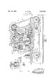
- Fig. l is a front elevational view of the invention (without cover) and with the bed plate in section.
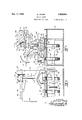
- Fig. 2 is a detail view of the presser foot.
- Fig. 3 is a plan View of the invention.
- Fig. 4 is a detail view of the cams operating the press plungers.
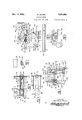
- Fig. 5 is a detail sectional View taken on the line 5-5 of Figure 1 showing the postage registering mechanism.
- Fig. 6 is a detail sectional view taken on the line 6-5 of Figure l and the line 65 of Figure '7 also showing the postage registering mechanism
- Fig. '7 is a rear detail view showing the postage registering mechanism.
- Fig. 8 is a detail view of the ratchet wheel communicating the drive between the operating mechanism and the counter.
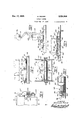
- Fig. 9 is a sectional view of the removable date stamp taken on the line 39 of Figure 3.
- Fig. 10 is a plan View of same.
- Fig. 11 is a sectional view taken on the line ll-ll of Figure 9.
- Fig. 12 is an end view showing the feed mechanism andassociated parts only.
- Fig. 13 is a detail front view showing the inker.
- Fig. 14 is a detail plan view of the inker.
- Fig. 15 is a sectional view taken on the line i5i 5 of Figure 1.
- Fig, 16 is an enlarged side view of the inker and 5 guides.
- Fig. 17 is a detail viewof the inking roller.
- Fig. 18 is an enlarged detail of the postage die operating slides.
- the numeral l indicates a base having outer walls 2, which support a bed plate 3 along which letters are adapted to be moved for postmarking.
- a cover 15 plate 4 Suitably supported above the bed plate is a cover 15 plate 4 which serves to support, a frame generally indicated by the numeral 5.
- the frame 5 consists of standards 6 and 1 between which are carried a lateral member 8 which includes a pair of cylindrical guides 9 and I9 and a pair of inclined 20 brackets ll having bearings l2 at their upper ends.
- Reciprocatingly mounted in the cylindrical guides 9 and ID are plungers l3 and I4 respectively, which are surrounded with springs ii for returning them to their upper or normal po- 2 sition, and the upper end of each plunger carries a roller 16.
- the plunger 13 is adapted to carry a date stamp
- the plunger I4 is adapted to carry a postage denomination stamp, both of which will be hereinafter referred to.
- bearings H At the upper end of the standards 6 and I are bearings H in which is journalled a cam shaft l8 which is fitted at its forward end with a slidably mounted sleeve IS.
- the sleeve I9 is provided with an enlargement 20 having a'bevel 2
- the sleeve is held against rotation upon the cam shaft It! by a slot and pin 24 or any other suitable means.
- the outer end of the sleeve I9 is provided with a clutch flange 25 which is adapted to engage corresponding clutch elements 26 upon the rear of a mitre gear 2'! which is freely rotatable upon the shaft it, but is held against endwise movement therealong by any appropriate means.
- the standard 1 supports a pair of transverse bearings 28 and 29 in which is journalled a drive shaft 39, which is adapted to be driven by a hand crank 3! or any suitable prime mover.
- the drive shaft 38 is provided with a mitre gear 32 which engages the gear 21 to drive it, and at its rear end it is provided with a pulley 33 from which the 55 drive is communicated through a belt 34 to the letter feed mechanism generally indicated by the numeral 35.
- the shaft 35 is fitted with a pulley 33 driven from the belt 34 and is also fitted with pulleys 49 and 4
- the pulley 48 drives through a belt 42 a small pulley 43 on the shaft 31, which shaft is fitted with a pair of friction wheels 44 whose peripheries extend through suitable openings in the bed plate 3 to engage and remove the letters after they have been stamped.
- Above the plate 4 and operating through suitable openings therethrough are spring pressed dead rolls 45 which bear down upon the letters directly above the friction wheels 44.
- drives a pulley 46 and the shaft 38 through a belt 41, thus driving a further pair of friction wheels 48 whose peripheries also project through suitable openings in the bed plate 7 3 to engage the letters to be stamped.
- a frame 49 in which a shaft 53 is journalled in slidably mounted bearings the bearings are downwardly pressed by springs 52, and the shaft is fitted with dead rolls 53 which are complementary to the friction wheels 48, so that letters may be conveyed toward and through the letter slot 54 which is defined between the plates 3 and 4.
- the friction wheels 44 run at a higher speed than the wheels 48, so that when a letter has been stamped it is carried out from the machine at a higher speed than that at which it enters.
- the sleeve I9 is urged by a spring 55 to bring the clutch flange 25 into engagement with the clutch elements 26.
- brackets 56 Extending upwards on opposite sides of the cylindrical guide I! are brackets 56 which carry at their upper ends, side bearings 51, see Figure 5, and on one of these brackets 56 a cranked support 58 is provided, which carries a small vertically mounted roller 59. This roller is adapted to be engaged by the cam 23 on the flange 22 of the sleeve
- a branch 69 extends from the cranked support 58 having a pin 6
- This bell crank is so formed at its upper arm as to provide a stop 63 for engaging the bevelled edge 2
- the lower arm of the bell crank 62 is transversely forked as at 64 and carries a pivot pin 65. Adjacent the fork 64 is a pair of spaced lugs 66 having slots 6'I carried upon the plate 4. An opening 68 is formed in the plate and through this a trigger 69 extends substantially into ccntactwith the plate 3 so as to be engaged by every letter which passes through the letter slot 54.
- the trigger 69 consists of a very light member hingedly mounted upon the pivot pin 65 and has secured to it atopposite edges a pair of arms I9 extending horizontally from the upper edge of the trigger fitted with rollers 1
- the slots 6'! are horizontal at one end and are directed downwardly at their outer end as at I2, the object of which is that when a letter engages the trigger $9 during its passage through the slot 54 it forces the trigger forwardly.
- the trigger has its rollers H in the horizontal portion of the slots 61 is kept in vertical position and transmits its movement to the bell crank 62.
- bell crank can be brought back to normal position by the action of the spring .13, when the cam 23 has again drawn the sleeve l8 inwardly to disconnect the drive.
- the cam shaft I8 is fitted with two yielding cams respectively numbered I4 and I5 both of which are identical in form and are set to the. same timing upon the shaft I8 and consist of a crank member I6, see detail in Figure 4, secured to the shaft and having at its outer end a curved member 'I'I pivotally connected thereto, which is adapted to engage in passing around with the shaft l8, the roller N5 of the plunger I3 or l4.
- the member I1 is outwardy pressed by a spring I8 of such strength that it will force the plunger downwardly into printing contact with the letter to be stamped against the action of the plunger spring I5, but will give to any letter of a greater thickness than normal.
- the plunger I3 is prog vided at its lower extremity with a tapered dove tail groove I9 and is adapted to detachably carry a stamp 80 bearing the city of origin of the letters to be mailed and type indicative of the date of issue of the postage, the stamp must be removable in order to change the date type and is therefore provided with a tongue 8
- the date stamp 88 is hingedly connected to a pair of parallel links 82 which in turn are connected to a crosshead slide 83 fitted within a rectangular drawer 84 which is provided in its bottom wall with a slot 85 to permit free downward movement of the lower link 82.
- the drawer and its attached stamp are adapted to be insertedthrough a suitable opening in the rear wall 86 of the cover of the machine.
- the drawer is fitted with a spindle 87 which carries the crosshead slide 83 on its inner end and is fitted with a collar 88 to limit the inward movement of the slide therealong.
- the spindle is fitted intermediate its length with a latch 89 for securing the drawer in position and to form an abutment for the crosshead, so that when the drawer is pushed into closing position the date stamp will be likewise pushed into proper position under the plunger l3, that it may pass freely through a suitable opening in the plate 4.
- a knob 90 is fitted to the outer end of the spindle 81 by which 7 0 the latter and its latch 89 are turned.
- is provided between the upper and lower links 82, which tends to hold the upper of them in contact with the upper wall of :the drawer until the stamp is in adjusted position.
- the rods xor presser'feet 93 project normally a slight distance below the datestamp 80, so as to engage a'letter and stop its movement along the slot.immediately .prior to the dating of the letter, which is accomplished by the presser feet engaging the letter in advance of the date-stamp, which continues .to descend after the feet have reached the letter.
- the plunger I4 is cut at itsbase'as at 9! to form a postage stamp having such printing as may be determined by the postal authorities.
- two rotatable printing dies 98 and '99 are mounted, both of which are fitted with pinions I00.
- Both of these dies bear the numerals O to 9 inclusive, which are so arranged about the periphery of the die as to enable any numeral to be printed as may be desired.
- the numerals on the die99 represent units of cents postage and the numerals on the die98 represent tens of cents postage.
- This rack is provided at its 'front end with an extension I03, see Figure 6, having a vertical slot I04.
- Bracketed out from the sides of the cylindrical guide I0 of the plunger I4 is a pair of guides I05 in each of which a sliding rod I06 is mounted.
- This rod is provided with a pin I01 which extends into the slot I04 of the extension I03 to the toothed rack I02, so that when the rod IDS is moved endwise the rack I02 is carried with it though the latter is free to move vertically with the plunger.
- the brackets II .and I2 support a fixed shaft I08 and on the ends of this shaft a pair of bell crank levers I09 and H0 are rockingly mounted, the lower arm of each is slotted as at I I I and connects with a sliding rod I06 to impart endwise movement to it.
- the upper arms of the levers terminate in press keys H2 and H3 respectively, which are adjacent a graduated arcuate scale I I4 having cents in units and tens indicated thereon. Suitable means is provided between the press keys and the scale so that the keys may be set and secured in any position.
- each of the bell crank levers I09 and H0 Extending beyond the shaft I08 from the boss of each of the bell crank levers I09 and H0 are quadrants I I5 having as many vertical teeth or stops H6 as there are numerals on the dies 98 and 99 all of which stops are regularly spaced from the axis of the shaft.
- the racks H8 each mesh with a pinion I23 which is suitably journalled and connected to .
- ratchet :wheel generally indicated by the numeral I -2'4,' see .i Figure 8.
- the ratchet wheels are providedwith-a'disc I25 carryingaipawl I26 which is adapted to engage internal ratchet teeth I27.
- the outer periphery of the ratchet wheels are provided with'gear rings I28 and I29 and these two rgear rings mesh respectively with gears I30 and 131 respectively, of .a counter or register I32 having a plurality of wheels bearing numerals indicative of dollars and .cents.
- the counter is of anysuitablettype and'the amount indicated thereon'is adapted to be increased in response to the turning .of :ithe gears I30 and I3I, the turning of .thea'giear .139 adding units of cents to the total and the turning of the gear I3! adding'tens of cents thereto.
- a cam lever I34 and an actuating lever I35 are-fixed.
- the cam lever I34 is spring ten- 1 sionedito keepits free end in contact with a cam I36 which is mounted upon the cam shaft I8.
- the free end of the actuating lever I35 passes through the slot I20 of one of the hollow plungers H'I controlling the addition of unit cents to the counter I32, between the ball I22 and the abutment I31.
- a cam lever I38 and an actuating lever I39 Freely'mounted upon the shaft I33 is a cam lever I38 and an actuating lever I39, the cam lever being spring tensioned to hold it in contact with a'cam I40 upon :the shaft I8 and the free end of the actuating lever I39 engaging, in the manner above describedthe plungercontrolling the addition of tens of .cents to the counter.
- the cams I39 and I40 are set at substantially degrees apart, so as to time the movement of "the two plungers, that the units addition can be completed before the addition of tens to the total on the counter.
- the tension on the cam levers 134 and .138 is such as to not only hold the levers in contact with their cams but to move the plungers III associated with them and actuate the counter also.
- the inking pad is carried in the tray by pins I52 secured to the side walls I.5I .andextending into the slots I 49.
- the base of the inking pad is cut away as at I53 in a'similar manner :to the bottom wall I44 of the tray I42 so as to afford free movement of the connecting rod 446.
- the springs 40 are connected at their inner end to the rear edge of the inking pad I50 and serve 'to-draw it rearwardly and downwardly into contact with the bottom wall of the tray.
- Mounted upon the cam shaft i8 is a cam I54 which operates a suitably journalled bell crank I 55 the lower end of which is pivotally attached to the spring connecting rod I '40 as at I 56.
- a pair of upstanding stops I 57 are provided for the purpose of arresting the rearward movement of the inking pad I59, so that the final rearward movement-of ithe inking tray I42 due to the swing of the bell crank I 55 actuated by the cam I54 will cause the inking pad to be raised by virtue 'of the pins I52 riding up the inclined plane defined by the slots I49, thus bringing the inking pad into inking contact with the postage and date stamps 91 and 80.
- a tubular shaft I58 extends lengthwise above the normal position of the inking tray, which is cut away on its upper side intermediate its ends as at I59 and is connected at one end with a suitable source of ink supply.
- Journalled upon the shaft is a perforate cylinder I 60 having a felt covering I6 I, thus constituting an inking roll I62.
- This inking roll is adapted to be engaged by the inking pad each time said pad is withdrawn from the stamps by the spring I63, which keeps the upper free end of the bell crank I55 in contact with the cam I54, so that ink falling from the open shaft I59 will saturate the inking roll I62 with ink, and in turn will moisten the inking pad I50.
- A'letter is fed into the slot 54 between the fric-' tion wheels 48 and the dead rolls 53, which carries it forwardly or to the right of Figure 1.
- the trigger 69 When the entering end of the letter strikes the trigger 69, it moves said trigger to the right, the trigger remaining in alignment with the bell crank 52 until it reaches the position shown in dotted line as at R.
- the stop 63 of the bell crank 62 becomes disengaged from the bevel 2
- cam I40 startsto swing its camlever -l38 and the actuating lever I39 to operate the plunger I I1 controlling the addition of tens of cents.
- the cam I54 starts to impart movement through the lever I55 to the inking tray I42 which during periods of rest is under the plungers I3 and I4, thus preventing any access to the date and postage stamps from below.
- the inking pad I50 is in contact with the stamps, so that as motion is imparted to the lever I55, the tray is first lowered from contact with the stamps and is then Withdrawn from under them, to be returned after the plungers I3 and I4 have been reciprocated and are about to come to rest in their normal retracted position.
- the cams I4 and I5 force these plungers downwards ber 11 of the cams, will give, so that the throw of the plungers will be reduced.
- a postage meter comprising a base having a letter slot, 2. plunger adapted for reciprocatory movement above the slot, a postage indicating stamp carried by the plunger, a drive shaft, means for feeding a letter through the slot, and means when the letter is in position under the stamp for effecting a drive from the drive shaft to the plunger to impress the stamp upon the letter, and a spring mounted presser foot carried by the plunger for arresting the letter immediately prior to impressing the stamp upon it.
- a plunger provided with a stamp for impressing postage upon a letter, a plate adapted to support the letter to be impressed, said cam being adapted to depress the plunger into printing engagement with the letter as the shaft is rotated, said cam being provided with resilient means whereby the stroke of the plunger is limited by the thickness of the letter to be impressed.
- a postage meter having a driven shaft and a cam
- said cam comprising a plate, a cam arm pivotally connected tothe plate, means for resiliently urging the cam arm radially outward, a plunger adapted to be depressed by the cam, a stamp at the base of the plunger for impress ing postage upon the letter when the shaft is rotated, and means for supporting the letter below the plunger.
- a postage meter having a reciprocable plunger fitted with a stamp for impressing postage upon a letter, a base having a slot through which the letter is adapted to be carried, said base having an aperture through which the stamp is adapted to pass into printing contact with the letter, an inking device normally closing the aperture and being adapted for removal prior to the movement of the plunger, said inking device comprising a movable slide carrying an inking pad, and means as the slide is brought to rest for raising the inking pad into contact with the stamp.
- a postage meter having a reciprocable plunger fitted with a stamp for impressing postage upon a letter, a base having a slot through which the letter is adapted to be carried, said base having an aperture through which the stamp is adapted to pass into printing contact with the letter, an inking .device normally closing the aperture and being adapted for removal prior to the movement of the plunger, said inking device comprising a movable slide carrying an ink- Eng pad, and means as the slide is brought to rest for raising the inking pad into contact with the stamp in a direction parallel to the longitudinal axis of the plunger and stamp.
- a postage meter enclosed within a casing and having a plunger fitted with a date stamp for impressing upon a letter, a. base having a slot through which the letter is adapted to pass for impressing, means for detachably connecting the stamp to the plunger, and means for withdrawing the stamp from the casing to change the date thereof, said means including a crosshead slide and a pair of links hingedly connected to the slide and the stamp.
- a postage meter enclosed within a casing and having a plunger fitted with a date stamp for impressing upon a letter, a base having a slot through which the letter is adapted to pass for impressing, means for detachably connecting the stamp to the plunger, said means extending to the exterior of the casing and to support the stamp whereby it is capable of reciprocating with the plunger, said means being an integral and operative element of the postage meter.
- a postage meter enclosed within a casing and having a plunger fitted with a date stamp 5 for impressing upon a letter, a base having a slot through which the letter is adapted to pass for impressing, means for detachably connecting the stamp to the plunger, said means comprising a slide carried within the casing, a pair of pivotally mounted parallel links secured at one end to the slide and at the other end to the stamp whereby the stamp is free to reciprocate with the plunger, said means being hingedly connected to the casing.
- a reciprocable plunger adapted to be sealed by proper authorities and privately used by an operator, a reciprocable plunger, a stamp upon the plunger for impressing postage paid upon a letter, said stamp having a die indicating different monetary denominations, means for setting the die to impress a desired monetary denomination, said means including a key extending to the exterior of the meter, said key being accessible for setting by the operator.
- a stamp upon the plunger for impressing postage paid upon a letter
- a rotatable die carried by the stamp having figures indicating difierent monetary values
- a pinion upon the die a rack engaging the pinion and movable transversely of the stroke of the plunger, said rack being carried in guides extending from the plunger, and means for imparting endwise movement to the rack and for permitting it to reciprocate with the plunger.
- a stamp upon the plunger Ior impressing postage paid upon a letter
- a rotatable die carried by the stamp having figures indicating different monetary values
- a pinion upon the die a rack engaging the pinion and movable transversely oi the stroke of the plunger, said rack being carried in guides extending from the plunger, and means for imparting endwise movement to the rack and for permitting it to: reciprocate with the plunger, said means including a slotted extension to the rack and an endwise movable rod having a pin engaging the slot of the extension, and means for imparting endwise movement to the rod.
Landscapes
- Devices For Checking Fares Or Tickets At Control Points (AREA)
Description
Dec. 17, 1935. M. MOORE 2,024,944
POSTAGE METER Filed Feb. 17, 1935 5 Sheets-Sheet 1 lNVENTOR MONTAGUE MOORE ATTORNEYS M. MOORE POSTAGE METER Dec. 17, 1935.
Filed Feb. 17, 1933 5 Sheets-Sheet 2 INVENTOR MONTAGUE MooRE ATTORNEYS M. MOORE POSTAGE METER Dec. 17, 1935.
Filed Feb. 17, 1933 5 Sheets-Sheet 3 muw m \\\\W m wg Q E Q4 M. MOORE POSTAGE METER Dec. 17, 1935.
Filed Feb. 17, 1933 5 SheetsSheet 4 M T N e V m MONTAGUE MOORE WA 6 ATTORNEYS M; MOORE POSTAGE METER Dec.- 17, 1935.
Filed Feb. 17, 1933 5 Sheets-Sheet 5 ff! If INVENTOR MONTAGUE MOORE W6? ATTORNEYS.
Patented Dec. 17, 1935 UNITED STATES ATENT OFFi-QE POSTAGE METER Montague Moore, Burnaby, British Columbia, Canada 11 Claims.
My invention relates to improvements in postage meters which are particularly adapted for manual or motor operation and of such simplicity and economy of construction as to render them commercially usable by small business operatives, whose mail output does not normally exceed fifty letters a day.
The objects of the machine are briefly to provide means whereby postage may be applied to mail matter from one to ninety-nine cents as desired; to automatically register the sum of all postage applied; to prevent an impression being made to any piece of mail matter except by the proper use of the machine; to prevent the registering of the machine except when a letter is being imprinted with the postage stam and to eject the letter from the machine at a higher speed than that of the letters entry to the machine.
The invention consists essentially of a feed mechanism, a reciprocatory printing head having postage indicia associated therewith, which is capable of being selectively changed to any desired denomination by one or more keys extending from the body of the machine whereby instant changes from one denomination to another may be made during the operation of the machine, and means for registering the sum of all postage applied, as will be more fully described in the following specification and shown in the accompanying drawings, in which:
Fig. l is a front elevational view of the invention (without cover) and with the bed plate in section.
Fig. 2 is a detail view of the presser foot.
5 Fig. 3 is a plan View of the invention.
Fig. 4 is a detail view of the cams operating the press plungers.
Fig. 5 is a detail sectional View taken on the line 5-5 of Figure 1 showing the postage registering mechanism.
Fig. 6 is a detail sectional view taken on the line 6-5 of Figure l and the line 65 of Figure '7 also showing the postage registering mechanism Fig. '7 is a rear detail view showing the postage registering mechanism.
Fig. 8 is a detail view of the ratchet wheel communicating the drive between the operating mechanism and the counter.
Fig. 9 is a sectional view of the removable date stamp taken on the line 39 of Figure 3.
Fig. 10 is a plan View of same.
Fig. 11 is a sectional view taken on the line ll-ll of Figure 9.
Fig. 12 is an end view showing the feed mechanism andassociated parts only.
Fig. 13 is a detail front view showing the inker.
Fig. 14 is a detail plan view of the inker.
Fig. 15 is a sectional view taken on the line i5i 5 of Figure 1.
Fig, 16 is an enlarged side view of the inker and 5 guides.
Fig. 17 is a detail viewof the inking roller.
Fig. 18 is an enlarged detail of the postage die operating slides.
In the drawings like characters of reference 10 indicate corresponding parts in each figure.
The numeral l indicates a base having outer walls 2, which support a bed plate 3 along which letters are adapted to be moved for postmarking. Suitably supported above the bed plate is a cover 15 plate 4 which serves to support, a frame generally indicated by the numeral 5. The frame 5 consists of standards 6 and 1 between which are carried a lateral member 8 which includes a pair of cylindrical guides 9 and I9 and a pair of inclined 20 brackets ll having bearings l2 at their upper ends. Reciprocatingly mounted in the cylindrical guides 9 and ID are plungers l3 and I4 respectively, which are surrounded with springs ii for returning them to their upper or normal po- 2 sition, and the upper end of each plunger carries a roller 16. The plunger 13 is adapted to carry a date stamp, and the plunger I4 is adapted to carry a postage denomination stamp, both of which will be hereinafter referred to.
At the upper end of the standards 6 and I are bearings H in which is journalled a cam shaft l8 which is fitted at its forward end with a slidably mounted sleeve IS. The sleeve I9 is provided with an enlargement 20 having a'bevel 2| at its intersection with the main portion of the sleeve and a flange 22 at its outer end which is provided on its inner face with a cam projection 23. The sleeve is held against rotation upon the cam shaft It! by a slot and pin 24 or any other suitable means.
The outer end of the sleeve I9 is provided with a clutch flange 25 which is adapted to engage corresponding clutch elements 26 upon the rear of a mitre gear 2'! which is freely rotatable upon the shaft it, but is held against endwise movement therealong by any appropriate means.
The standard 1 supports a pair of transverse bearings 28 and 29 in which is journalled a drive shaft 39, which is adapted to be driven by a hand crank 3! or any suitable prime mover. The drive shaft 38 is provided with a mitre gear 32 which engages the gear 21 to drive it, and at its rear end it is provided with a pulley 33 from which the 55 drive is communicated through a belt 34 to the letter feed mechanism generally indicated by the numeral 35.
Journalled transversely below the bed plate 3 are shafts 36, 31 and 38. The shaft 35 is fitted with a pulley 33 driven from the belt 34 and is also fitted with pulleys 49 and 4|. The pulley 48 drives through a belt 42 a small pulley 43 on the shaft 31, which shaft is fitted with a pair of friction wheels 44 whose peripheries extend through suitable openings in the bed plate 3 to engage and remove the letters after they have been stamped. Above the plate 4 and operating through suitable openings therethrough are spring pressed dead rolls 45 which bear down upon the letters directly above the friction wheels 44. The pulley 4| drives a pulley 46 and the shaft 38 through a belt 41, thus driving a further pair of friction wheels 48 whose peripheries also project through suitable openings in the bed plate 7 3 to engage the letters to be stamped.
Further friction wheels will be provided to withdraw letters from a feed tray for delivery to the machine, but as this does not form part of the invention, reference only is made to them.
Mounted onthe plate 4 is a frame 49 in which a shaft 53 is journalled in slidably mounted bearings the bearings are downwardly pressed by springs 52, and the shaft is fitted with dead rolls 53 which are complementary to the friction wheels 48, so that letters may be conveyed toward and through the letter slot 54 which is defined between the plates 3 and 4. Itwill be noticed that the friction wheels 44 run at a higher speed than the wheels 48, so that when a letter has been stamped it is carried out from the machine at a higher speed than that at which it enters. The sleeve I9 is urged by a spring 55 to bring the clutch flange 25 into engagement with the clutch elements 26.
Extending upwards on opposite sides of the cylindrical guide I!) are brackets 56 which carry at their upper ends, side bearings 51, see Figure 5, and on one of these brackets 56 a cranked support 58 is provided, which carries a small vertically mounted roller 59. This roller is adapted to be engaged by the cam 23 on the flange 22 of the sleeve |9 to move said sleeve against its spring 55 and disconnect the drive between the clutch 25 and the clutch 2B. A branch 69 extends from the cranked support 58 having a pin 6| at its outer end about which a bell crank 62 is pivotally mounted. This bell crank is so formed at its upper arm as to provide a stop 63 for engaging the bevelled edge 2| of the sleeve l9, thus preventing the spring 55 from moving the sleeve endwise to establish the drive from the shaft 30 to the cam shaft IS. The lower arm of the bell crank 62 is transversely forked as at 64 and carries a pivot pin 65. Adjacent the fork 64 is a pair of spaced lugs 66 having slots 6'I carried upon the plate 4. An opening 68 is formed in the plate and through this a trigger 69 extends substantially into ccntactwith the plate 3 so as to be engaged by every letter which passes through the letter slot 54. The trigger 69 consists of a very light member hingedly mounted upon the pivot pin 65 and has secured to it atopposite edges a pair of arms I9 extending horizontally from the upper edge of the trigger fitted with rollers 1| at their extremities, which have their movement in the slots 61. The slots 6'! are horizontal at one end and are directed downwardly at their outer end as at I2, the object of which is that when a letter engages the trigger $9 during its passage through the slot 54 it forces the trigger forwardly. The trigger has its rollers H in the horizontal portion of the slots 61 is kept in vertical position and transmits its movement to the bell crank 62. As soon as the rollers enter 5 the inclined portion I2 of the slots the upper arm of the bell crank will have been lowered and the stop member 63 thereon lowered out of contact with the bevel 2| of the sleeve I9, thus allowing said sleeve to move endwise along the cam shaft l8 and cause the clutch elements 25 and 26 to engage that the cam shaft may be rotated. Iinmediately following this part of the bell crank movement, the letter, still being urged through the slot 54 by the friction wheels will continue to move the trigger, but as the rollers pass downwards along the inclined portions "I2 of the slots the trigger will be free to swing about the pivot pin 65, thus allowing the free end of the trigger to be lifted clear of the letter, so that when the letter has been stamped and passed through, the
bell crank can be brought back to normal position by the action of the spring .13, when the cam 23 has again drawn the sleeve l8 inwardly to disconnect the drive.
The cam shaft I8 is fitted with two yielding cams respectively numbered I4 and I5 both of which are identical in form and are set to the. same timing upon the shaft I8 and consist of a crank member I6, see detail in Figure 4, secured to the shaft and having at its outer end a curved member 'I'I pivotally connected thereto, which is adapted to engage in passing around with the shaft l8, the roller N5 of the plunger I3 or l4. The member I1 is outwardy pressed by a spring I8 of such strength that it will force the plunger downwardly into printing contact with the letter to be stamped against the action of the plunger spring I5, but will give to any letter of a greater thickness than normal. The plunger I3 is prog vided at its lower extremity with a tapered dove tail groove I9 and is adapted to detachably carry a stamp 80 bearing the city of origin of the letters to be mailed and type indicative of the date of issue of the postage, the stamp must be removable in order to change the date type and is therefore provided with a tongue 8|, see Figures 9, 10 and 11, capable of insertion from the rear of the machine into the groove I9 of the plunger l3. The date stamp 88 is hingedly connected to a pair of parallel links 82 which in turn are connected to a crosshead slide 83 fitted within a rectangular drawer 84 which is provided in its bottom wall with a slot 85 to permit free downward movement of the lower link 82. The drawer and its attached stamp are adapted to be insertedthrough a suitable opening in the rear wall 86 of the cover of the machine. The drawer is fitted with a spindle 87 which carries the crosshead slide 83 on its inner end and is fitted with a collar 88 to limit the inward movement of the slide therealong. The spindle is fitted intermediate its length with a latch 89 for securing the drawer in position and to form an abutment for the crosshead, so that when the drawer is pushed into closing position the date stamp will be likewise pushed into proper position under the plunger l3, that it may pass freely through a suitable opening in the plate 4. A knob 90 is fitted to the outer end of the spindle 81 by which 7 0 the latter and its latch 89 are turned.
In order to support the stamp 80 in alignment with its connection on the plunger l3, a tension spring 9| is provided between the upper and lower links 82, which tends to hold the upper of them in contact with the upper wall of :the drawer until the stamp is in adjusted position. The insertion of the type into the stamp indicative of date will be made by any appropriate means.
To one side of the plunger :I3 apair of spaced guides 92 are secured, see Figures 1 and 2, in which guides a pair of vertical rods 93, which constitute a pair of :presser feet, are slidably mounted. The rods are urged downwardly by springs 94 and are limited in their downward movement by collars which are .secured to the rods below the springs, the lower end of each rod is preferably serrated as at 96. The rods xor presser'feet 93 project normally a slight distance below the datestamp 80, so as to engage a'letter and stop its movement along the slot.immediately .prior to the dating of the letter, which is accomplished by the presser feet engaging the letter in advance of the date-stamp, which continues .to descend after the feet have reached the letter. The plunger I4 is cut at itsbase'as at 9! to form a postage stamp having such printing as may be determined by the postal authorities. At the sides of the stamp two rotatable printing dies 98 and '99 are mounted, both of which are fitted with pinions I00. Both of these dies bear the numerals O to 9 inclusive, which are so arranged about the periphery of the die as to enable any numeral to be printed as may be desired. The numerals on the die99 represent units of cents postage and the numerals on the die98 represent tens of cents postage.
Extending from the sides of the plunger I4 are guides IOI, see enlarged details in Figure '18, in each of which a toothed rack I02 is slidably mounted, for imparting rotation to the die to dispose a desired'numeral in position for printing. This rack is provided at its 'front end with an extension I03, see Figure 6, having a vertical slot I04. Bracketed out from the sides of the cylindrical guide I0 of the plunger I4 is a pair of guides I05 in each of which a sliding rod I06 is mounted. This rod is provided with a pin I01 which extends into the slot I04 of the extension I03 to the toothed rack I02, so that when the rod IDS is moved endwise the rack I02 is carried with it though the latter is free to move vertically with the plunger.
The brackets II .and I2 support a fixed shaft I08 and on the ends of this shaft a pair of bell crank levers I09 and H0 are rockingly mounted, the lower arm of each is slotted as at I I I and connects with a sliding rod I06 to impart endwise movement to it. The upper arms of the levers terminate in press keys H2 and H3 respectively, which are adjacent a graduated arcuate scale I I4 having cents in units and tens indicated thereon. Suitable means is provided between the press keys and the scale so that the keys may be set and secured in any position. Extending beyond the shaft I08 from the boss of each of the bell crank levers I09 and H0 are quadrants I I5 having as many vertical teeth or stops H6 as there are numerals on the dies 98 and 99 all of which stops are regularly spaced from the axis of the shaft. Carried by the brackets 56, see Figures 5 and 6, are hollow plungers I I I each having at its rear end a rack H8 and at its forward end a tongue II9. Each plunger is longitudinally slotted as at I20 and is fitted with a spring I2I and a ball I22 which is urged against the front face of an arm to be hereinafter described.
The racks H8 each mesh with a pinion I23 which is suitably journalled and connected to .a
ratchet :wheel, generally indicated by the numeral I -2'4,' see .iFigure 8. The ratchet wheels are providedwith-a'disc I25 carryingaipawl I26 which is adapted to engage internal ratchet teeth I27. The outer periphery of the ratchet wheels are provided with'gear rings I28 and I29 and these two rgear rings mesh respectively with gears I30 and 131 respectively, of .a counter or register I32 having a plurality of wheels bearing numerals indicative of dollars and .cents. The counter is of anysuitablettype and'the amount indicated thereon'is adapted to be increased in response to the turning .of :ithe gears I30 and I3I, the turning of .thea'giear .139 adding units of cents to the total and the turning of the gear I3! adding'tens of cents thereto.
Suitably journalled at the rear of the cylindrical guides 9 and [0 is'a shaft I33, see Figure 7, upon which a cam lever I34 and an actuating lever I35 are-fixed. The cam lever I34 is spring ten- 1 sionedito keepits free end in contact with a cam I36 which is mounted upon the cam shaft I8. The free end of the actuating lever I35 passes through the slot I20 of one of the hollow plungers H'I controlling the addition of unit cents to the counter I32, between the ball I22 and the abutment I31.
Freely'mounted upon the shaft I33 is a cam lever I38 and an actuating lever I39, the cam lever being spring tensioned to hold it in contact with a'cam I40 upon :the shaft I8 and the free end of the actuating lever I39 engaging, in the manner above describedthe plungercontrolling the addition of tens of .cents to the counter.
The cams I39 and I40 are set at substantially degrees apart, so as to time the movement of "the two plungers, that the units addition can be completed before the addition of tens to the total on the counter. The tension on the cam levers 134 and .138 is such as to not only hold the levers in contact with their cams but to move the plungers III associated with them and actuate the counter also.
"Mountodzabove the bed plate 4 are two transversely arranged rods I4I slidably carrying an inking tray :I42 having side walls I43 and a .bottom wall 144, .see Figures 13 to 17 inclusive. A medial portion of said bottom wall is provided with :a gap 145 at the base of which a light spring connecting rod is secured. Extending from the rear of the tray are two projecting lugs I41 which are eyed to receive the ends of a pair of tension springs I49. The side walls I43 of the tray "I42 are each p-rovided with parallel slots I40, see Figure 16, which are inclined downwardly to the rear-of the tray at approximately 45 degrees. An inking pad I50 having side walls I5! is carried in the tray by pins I52 secured to the side walls I.5I .andextending into the slots I 49. The base of the inking pad is cut away as at I53 in a'similar manner :to the bottom wall I44 of the tray I42 so as to afford free movement of the connecting rod 446. The springs 40 are connected at their inner end to the rear edge of the inking pad I50 and serve 'to-draw it rearwardly and downwardly into contact with the bottom wall of the tray. Mounted upon the cam shaft i8 is a cam I54 which operates a suitably journalled bell crank I 55 the lower end of which is pivotally attached to the spring connecting rod I '40 as at I 56.
A pair of upstanding stops I 57 are provided for the purpose of arresting the rearward movement of the inking pad I59, so that the final rearward movement-of ithe inking tray I42 due to the swing of the bell crank I 55 actuated by the cam I54 will cause the inking pad to be raised by virtue 'of the pins I52 riding up the inclined plane defined by the slots I49, thus bringing the inking pad into inking contact with the postage and date stamps 91 and 80. V
A tubular shaft I58 extends lengthwise above the normal position of the inking tray, which is cut away on its upper side intermediate its ends as at I59 and is connected at one end with a suitable source of ink supply. Journalled upon the shaft is a perforate cylinder I 60 having a felt covering I6 I, thus constituting an inking roll I62. This inking roll is adapted to be engaged by the inking pad each time said pad is withdrawn from the stamps by the spring I63, which keeps the upper free end of the bell crank I55 in contact with the cam I54, so that ink falling from the open shaft I59 will saturate the inking roll I62 with ink, and in turn will moisten the inking pad I50.
Having thus described the several parts of my invention, I will now briefly explain its operation.
It will beassumed that the drive shaft 30 is continually rotating.
A'letter is fed into the slot 54 between the fric-' tion wheels 48 and the dead rolls 53, which carries it forwardly or to the right of Figure 1. When the entering end of the letter strikes the trigger 69, it moves said trigger to the right, the trigger remaining in alignment with the bell crank 52 until it reaches the position shown in dotted line as at R. By this time the stop 63 of the bell crank 62 becomes disengaged from the bevel 2| of the enlargement 20 of the sleeve I9, thus allowing the spring 55 to come into action and move the sleeve to establish a driving connection between the shaft 30 and the cam shaft I8 and setting said shaft in motion. The subsequent thrust upon the trigger causes it to swing upon the pin 65 to allowthe letter to pass beneath it as soon as it has been impressed with postage. Assuming that thirty three cents postage is to be applied to each letter the keys H2 and H3 are each depressed to read 33 on the scale. The movement of the bell crank levers I09 and I II] will move their respective sliding rods I06 to the right, see Figure 6, and impart rotation through the toothed racks I02 to the pinions I and their dies 98 and 99 to set them to print the selected numerals. Coincident with the movement of the bell crank levers I I 0 the quadrants I I are raised, thus disposing the third from the end of the teeth H5 in alignment with the tongues II9 of the plungers H1.
The rotation of the shaft I 8 will cause the units cam I36 to swing its lever I34 and the actuating lever I35 to thrust the plunger II! of the units 7 counter back until its tongue engages the tooth I I6 of the quadrant I I5of the units key H2 when the plunger movement will be arrested, the continued movement of the actuating lever I 35 mere- 1y serving to compress the plunger spring I2I.
When the free extremity of the cam I36 has passed the upper end of the cam lever to allow the latter to'return to normal position, the actuating lever I35 also returns and when its free end engages the abutment I31 of the plunger it moves said plunger to the right as in Figure 6, thus rotating the pinion I24 and increasing the total registered on the counter by three. Obviously the return rotation of the pinion I 23 results only in a slippage of the pawl I26 and the rotation ofthe' disk I25, so that no change takes place on the counter.
As soon as the units plunger has finished on its counting stroke or movement to the right, the
cam I40 startsto swing its camlever -l38 and the actuating lever I39 to operate the plunger I I1 controlling the addition of tens of cents.
The operation of the parts in the train controlling tens is identical with those previously 5 described, so that additional description is not deemed necessary, but the tens are added after the units movement has been completed, so that accurate addition is obtained.
Simultaneously with the commencing of the registering movement the cam I54 starts to impart movement through the lever I55 to the inking tray I42 which during periods of rest is under the plungers I3 and I4, thus preventing any access to the date and postage stamps from below. During the periods of rest, the inking pad I50 is in contact with the stamps, so that as motion is imparted to the lever I55, the tray is first lowered from contact with the stamps and is then Withdrawn from under them, to be returned after the plungers I3 and I4 have been reciprocated and are about to come to rest in their normal retracted position. As soon as the inking tray I42 is clear of the plungers I3 and I4, the cams I4 and I5 force these plungers downwards ber 11 of the cams, will give, so that the throw of the plungers will be reduced.
'When the plungers are returned to their normal position and the presser feet removed from contact with the letter, the letter is again permitted to move in a forward direction, its ini-.
tial movement swinging the trigger beyond the dotted line position shown in Figure l as at R, so that the letter may be engaged between the dead rolls 45 and the friction wheels 44, which being rotated at a greater peripheral velocity than the friction wheels 48 will discharge the letter rapidly. When the entire length of the letter has passed beneath the trigger, the latter assumes its vertical position and the spring 13 tends to move the bell crank 62 to normal position, which normal position is attained as soon as the cam 23 through engagement with the roller 59 has forced the sleeve l9 against the spring '55, so that the stop 63 can engage the bevel 2|, thereby disconnecting the drive between the drive shaft 30 and the cam shaft I8.
What I claim as my invention is:
l. A postage meter comprising a base having a letter slot, 2. plunger adapted for reciprocatory movement above the slot, a postage indicating stamp carried by the plunger, a drive shaft, means for feeding a letter through the slot, and means when the letter is in position under the stamp for effecting a drive from the drive shaft to the plunger to impress the stamp upon the letter, and a spring mounted presser foot carried by the plunger for arresting the letter immediately prior to impressing the stamp upon it.
2. In a postage meter having a driven shaft and a cam, a plunger provided with a stamp for impressing postage upon a letter, a plate adapted to support the letter to be impressed, said cam being adapted to depress the plunger into printing engagement with the letter as the shaft is rotated, said cam being provided with resilient means whereby the stroke of the plunger is limited by the thickness of the letter to be impressed.
3. In a postage meter having a driven shaft and a cam, said cam comprising a plate, a cam arm pivotally connected tothe plate, means for resiliently urging the cam arm radially outward, a plunger adapted to be depressed by the cam, a stamp at the base of the plunger for impress ing postage upon the letter when the shaft is rotated, and means for supporting the letter below the plunger.
4. In a postage meter having a reciprocable plunger fitted with a stamp for impressing postage upon a letter, a base having a slot through which the letter is adapted to be carried, said base having an aperture through which the stamp is adapted to pass into printing contact with the letter, an inking device normally closing the aperture and being adapted for removal prior to the movement of the plunger, said inking device comprising a movable slide carrying an inking pad, and means as the slide is brought to rest for raising the inking pad into contact with the stamp.
5. In a postage meter having a reciprocable plunger fitted with a stamp for impressing postage upon a letter, a base having a slot through which the letter is adapted to be carried, said base having an aperture through which the stamp is adapted to pass into printing contact with the letter, an inking .device normally closing the aperture and being adapted for removal prior to the movement of the plunger, said inking device comprising a movable slide carrying an ink- Eng pad, and means as the slide is brought to rest for raising the inking pad into contact with the stamp in a direction parallel to the longitudinal axis of the plunger and stamp.
6. In a postage meter enclosed within a casing and having a plunger fitted with a date stamp for impressing upon a letter, a. base having a slot through which the letter is adapted to pass for impressing, means for detachably connecting the stamp to the plunger, and means for withdrawing the stamp from the casing to change the date thereof, said means including a crosshead slide and a pair of links hingedly connected to the slide and the stamp.
'7. In a postage meter enclosed within a casing and having a plunger fitted with a date stamp for impressing upon a letter, a base having a slot through which the letter is adapted to pass for impressing, means for detachably connecting the stamp to the plunger, said means extending to the exterior of the casing and to support the stamp whereby it is capable of reciprocating with the plunger, said means being an integral and operative element of the postage meter.
8. In a postage meter enclosed within a casing and having a plunger fitted with a date stamp 5 for impressing upon a letter, a base having a slot through which the letter is adapted to pass for impressing, means for detachably connecting the stamp to the plunger, said means comprising a slide carried within the casing, a pair of pivotally mounted parallel links secured at one end to the slide and at the other end to the stamp whereby the stamp is free to reciprocate with the plunger, said means being hingedly connected to the casing.
9. In a postage meter adapted to be sealed by proper authorities and privately used by an operator, a reciprocable plunger, a stamp upon the plunger for impressing postage paid upon a letter, said stamp having a die indicating different monetary denominations, means for setting the die to impress a desired monetary denomination, said means including a key extending to the exterior of the meter, said key being accessible for setting by the operator.
10. In a postage meter having a reciprocable plunger, a stamp upon the plunger for impressing postage paid upon a letter, a rotatable die carried by the stamp having figures indicating difierent monetary values, a pinion upon the die, a rack engaging the pinion and movable transversely of the stroke of the plunger, said rack being carried in guides extending from the plunger, and means for imparting endwise movement to the rack and for permitting it to reciprocate with the plunger.
11. In a postage meter having a reciprocable plunger, a stamp upon the plunger Ior impressing postage paid upon a letter, a rotatable die carried by the stamp having figures indicating different monetary values, a pinion upon the die, a rack engaging the pinion and movable transversely oi the stroke of the plunger, said rack being carried in guides extending from the plunger, and means for imparting endwise movement to the rack and for permitting it to: reciprocate with the plunger, said means including a slotted extension to the rack and an endwise movable rod having a pin engaging the slot of the extension, and means for imparting endwise movement to the rod.
MONTAGUE MOORE.
Publications (1)
| Publication Number | Publication Date |
|---|---|
| US2024944A true US2024944A (en) | 1935-12-17 |
Family
ID=3427575
Family Applications (1)
| Application Number | Title | Priority Date | Filing Date |
|---|---|---|---|
| US2024944D Expired - Lifetime US2024944A (en) | Postage meter |
Country Status (1)
| Country | Link |
|---|---|
| US (1) | US2024944A (en) |
-
0
- US US2024944D patent/US2024944A/en not_active Expired - Lifetime
Similar Documents
| Publication | Publication Date | Title |
|---|---|---|
| US2152204A (en) | Postage meter | |
| US2136461A (en) | Marking machine | |
| US2043600A (en) | Printing machine | |
| US2005038A (en) | Value stamping device | |
| US2024944A (en) | Postage meter | |
| US2036538A (en) | Parcel post weighing and stamp printing machine | |
| US2044367A (en) | Ticket printing, issuing, and accounting machine | |
| US2328097A (en) | Display printing machine | |
| US2524387A (en) | Key controlled type selection | |
| US2194305A (en) | Totalizer system | |
| US1990304A (en) | Combined recording and registering postal scale | |
| US2679798A (en) | Record controlled address type printing machine | |
| US1530852A (en) | Printing mechanism for parcel-post-postage meter machines | |
| US2271106A (en) | Laundry marking machine | |
| US345624A (en) | Machine foe printing | |
| US2336111A (en) | Tabulating machine | |
| US2335718A (en) | Value stamping and vending machine | |
| US2003218A (en) | Adjustable printing mechanism | |
| US1082957A (en) | Apparatus for printing and issuing tickets or checks of different denominations and for registering and totaling numbers and indicating the totals. | |
| US1435171A (en) | X x che check issuing and printing | |
| US1607705A (en) | Stamping and registering or counting apparatus | |
| SU32215A1 (en) | Vacation and stamping machine for theater and other tickets | |
| US2743669A (en) | Machines for printing and issuing postal orders and like forms | |
| US1236186A (en) | Printing-press. | |
| US1146571A (en) | Check-protector. |