US2024933A - Slicing machine - Google Patents
Slicing machine Download PDFInfo
- Publication number
- US2024933A US2024933A US727998A US72799834A US2024933A US 2024933 A US2024933 A US 2024933A US 727998 A US727998 A US 727998A US 72799834 A US72799834 A US 72799834A US 2024933 A US2024933 A US 2024933A
- Authority
- US
- United States
- Prior art keywords
- knife
- slicing machine
- support
- slicing
- substance
- Prior art date
- Legal status (The legal status is an assumption and is not a legal conclusion. Google has not performed a legal analysis and makes no representation as to the accuracy of the status listed.)
- Expired - Lifetime
Links
Images


Classifications
-
- B—PERFORMING OPERATIONS; TRANSPORTING
- B26—HAND CUTTING TOOLS; CUTTING; SEVERING
- B26D—CUTTING; DETAILS COMMON TO MACHINES FOR PERFORATING, PUNCHING, CUTTING-OUT, STAMPING-OUT OR SEVERING
- B26D1/00—Cutting through work characterised by the nature or movement of the cutting member or particular materials not otherwise provided for; Apparatus or machines therefor; Cutting members therefor
- B26D1/01—Cutting through work characterised by the nature or movement of the cutting member or particular materials not otherwise provided for; Apparatus or machines therefor; Cutting members therefor involving a cutting member which does not travel with the work
- B26D1/12—Cutting through work characterised by the nature or movement of the cutting member or particular materials not otherwise provided for; Apparatus or machines therefor; Cutting members therefor involving a cutting member which does not travel with the work having a cutting member moving about an axis
- B26D1/14—Cutting through work characterised by the nature or movement of the cutting member or particular materials not otherwise provided for; Apparatus or machines therefor; Cutting members therefor involving a cutting member which does not travel with the work having a cutting member moving about an axis with a circular cutting member, e.g. disc cutter
- B26D1/157—Cutting through work characterised by the nature or movement of the cutting member or particular materials not otherwise provided for; Apparatus or machines therefor; Cutting members therefor involving a cutting member which does not travel with the work having a cutting member moving about an axis with a circular cutting member, e.g. disc cutter rotating about a movable axis
- B26D1/18—Cutting through work characterised by the nature or movement of the cutting member or particular materials not otherwise provided for; Apparatus or machines therefor; Cutting members therefor involving a cutting member which does not travel with the work having a cutting member moving about an axis with a circular cutting member, e.g. disc cutter rotating about a movable axis mounted on a movable carriage
-
- Y—GENERAL TAGGING OF NEW TECHNOLOGICAL DEVELOPMENTS; GENERAL TAGGING OF CROSS-SECTIONAL TECHNOLOGIES SPANNING OVER SEVERAL SECTIONS OF THE IPC; TECHNICAL SUBJECTS COVERED BY FORMER USPC CROSS-REFERENCE ART COLLECTIONS [XRACs] AND DIGESTS
- Y10—TECHNICAL SUBJECTS COVERED BY FORMER USPC
- Y10T—TECHNICAL SUBJECTS COVERED BY FORMER US CLASSIFICATION
- Y10T83/00—Cutting
- Y10T83/202—With product handling means
- Y10T83/2033—Including means to form or hold pile of product pieces
- Y10T83/2037—In stacked or packed relation
- Y10T83/2046—Including means to move stack bodily
- Y10T83/2048—By movement of stack holder
- Y10T83/205—By timed relocation of holder along path of stack gscheme-change-itemth
-
- Y—GENERAL TAGGING OF NEW TECHNOLOGICAL DEVELOPMENTS; GENERAL TAGGING OF CROSS-SECTIONAL TECHNOLOGIES SPANNING OVER SEVERAL SECTIONS OF THE IPC; TECHNICAL SUBJECTS COVERED BY FORMER USPC CROSS-REFERENCE ART COLLECTIONS [XRACs] AND DIGESTS
- Y10—TECHNICAL SUBJECTS COVERED BY FORMER USPC
- Y10T—TECHNICAL SUBJECTS COVERED BY FORMER US CLASSIFICATION
- Y10T83/00—Cutting
- Y10T83/647—With means to convey work relative to tool station
- Y10T83/654—With work-constraining means on work conveyor [i.e., "work-carrier"]
- Y10T83/6563—With means to orient or position work carrier relative to tool station
-
- Y—GENERAL TAGGING OF NEW TECHNOLOGICAL DEVELOPMENTS; GENERAL TAGGING OF CROSS-SECTIONAL TECHNOLOGIES SPANNING OVER SEVERAL SECTIONS OF THE IPC; TECHNICAL SUBJECTS COVERED BY FORMER USPC CROSS-REFERENCE ART COLLECTIONS [XRACs] AND DIGESTS
- Y10—TECHNICAL SUBJECTS COVERED BY FORMER USPC
- Y10T—TECHNICAL SUBJECTS COVERED BY FORMER US CLASSIFICATION
- Y10T83/00—Cutting
- Y10T83/768—Rotatable disc tool pair or tool and carrier
- Y10T83/7755—Carrier for rotatable tool movable during cutting
- Y10T83/7763—Tool carrier reciprocable rectilinearly
- Y10T83/7776—With means to reciprocate carrier
- Y10T83/778—And means to rotate tool
Definitions
- This invention relates to slicing machines for bacon and other substances.
- My invention has for its main object to provide an improved slicing machine in which the substance can be out either perpendicularly throughthe thickness or else obliquely thereto and therefore to an increased width as compared with the actual thickness of the piece; this is particularly advantageous in slicing thin pieces of streaky bacon, the'narrow rashers obtained by the ordinary method of cutting having a considerably lower selling price or being less in demand than wider rashers cut from the thicker part of the same substance.
- Another object of my invention is to provide an improved arrangement of slicing machine, in which the slices are cut from the lower end of a length of substance occupying an approximately vertical position, preferably adjustable to an inclined position to allow of the oblique slicing of a part and brought back to the vertical forthe normal slicing of a thicker part.
- a further object of my invention is to provide an improved slicing machine in which the angular position of an approximately vertical length of substance, sliced by a horizontal cutting knife at its lower end, is adjusted in conjunction with the feed movement which advances the piece downwards towards the cutting plane after each slice has been out.
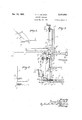
- Fig. 1 is a front elevation of the machine, with the cover partly broken away.
- I Fig. 2 is a plan view.
- Fig. 3 is a part sectional elevation, seen on the line 33 of Fig. 2.
- Fig. 4 is a plan view of a detail in the feed mechanism.
- Figs. 5 and 6 are diagrams illustrating the oblique and perpendicular cutting effected by my invention.
- the slicing machine comprises a base at, having at one end a head I) and at the other end a pair of lugs 01 with a pair of parallel rails at extending horizontally from the head into the lugs.
- These rails form guides for a slide e having four eyes e fitting in pairs upon the two rails.
- the slide carries a rotary disc knife 1 mounted upon a vertical shaft f journaled in a support g and driven by a bevel-reducing gear J from an electric motor h secured upon the slide.
- the shaft f extends through the slide and its lower end is fitted with a pinion i meshing with a gear wheel :i rotatably mounted on a stud ⁇ i beneath the slide.
- the gear wheel 7' forms a crank disc, being provided 5 with a crank pin 7' engaged by one end of a link It, the: other end of which is mounted upon a fixed pivot is on the center line of the base.
- the rotation of the motor it will drive the knife f, at half speed for example, and will also 10 revolve the crank pin 7' at one-tenth speed for example; the slide will therefore reciprocate at slow speed along the rails d, causing the rotating knife 1 to move to and fro in a horizontal plane just below the top of the head I).
- a de- 15 tachable cover plate I secured to the edges of the base, encloses the motor and gearing, but allows the knife to project at one side as it approaches the head; during the return movement, a scraper m consisting of a steel strip having 20 one end clamped around the knife support g, is brought into contact with the revolving knife by means of an adjustable cam m secured on the inside of the cover plate 1, the contact lasting for a short period suflicient to remove any 25 fat or particles adhering to the surface.
- the substance to be sliced is mounted upon a meat plate or holder n having a pair of pillars n and a clamping bar 11" of the known kind, this meat plate being slidable upon a backing 30 table or support 0 under the control of a feed screw 10 fitted with a handle 12 a cranked arm n secured to the plate n is formed as a nut at its extremity n to engage the screw 10.
- the table 0 is mounted upon a hinge at 0 at the top of a 35 bracket o secured on the head b; this hinge 0 which is set obliquely to the rails d, as seen in Fig. 2, allows the table to be turned from the vertical position shown in Figs.
- a toothed segment q shown as formed integral with one edge of the table, this segment meshing with a worm q upon a vertical shaft (1 rotatably mounted in a socket b secured 5 upon the top of the head b by screws 73 passing up through an interior washer plate 19 the lower end of this shaft (1 is squared at q and the extremity is journaled in a boss a in the base of the machine.
- a gear sleeve comprising a bevel wheel 1' and a spur wheel 1' with an intermediate grooved portion r engaged by a striking fork r by means of an external handle r
- the fork can be operated to lift the gear sleeve until the bevel wheel r comes into mesh with a second bevel wheel r rotatably mounted in the wall of the head 17 and operated by an external handle 1
- the handle while the bevel wheelsare in mesh, the worm q can be caused to rock the table about its hinge so as to obtain the horizontal position or any desired inclination to the vertical.
- the spur wheel 1 meshes with a second spur wheel 8 fitted upon the squared lower end of a vertical shaft s having its lower extremity journaled in a second boss; a in the base of the machine; the upper end of this shaft is journaled in a lateral extension 0 of. the bracket 0 and its. extremity carries a bevel, pinion s meshing with a bevel wheel s rotatably mounted upon the hinge pin 0 this bevel wheel being also'in, mesh with a. second bevel pinion p at. the lower end of the feed screw 12, which is rotatably supported in a boss 0 on the back of the table 0.
- the feed screw can be operated irrespective of the angular position of the table, by the rotation of the shaft s the movement being reversed by the bevel gearing s s p
- the automatic feed motion is produced by a pawl t engaging the spur wheel s, Fig. 4, this pawl being mounted upon a slide rod t guided by a saddle t on the base of the machine; the other end of the rod is secured to. a tappet t slidably mounted upon one of the rails 11 between the two eyes e the alternate. engagement of which with the tappet t as the slide e reciprocates along the rails, causes the. pawl.- fitted rod t to rotate the spur wheel 8 and shaft s and then to return to its former position.
- the plate it, which is intended to receive.
- the table 0 may be turned up into the vertical position and the slices cut perpendicularly through the thickness, the gear sleeve rr being held in the raised position so that the worm 11 is not driven; in cutting a piece of uniformly narrow bacon, the table may be adjusted to a suitable inclination, for example 45 degrees, and the slices cut obliquely through the thickness, so that they are of considerably greater width than 5 the actual thickness of the piece, the worm q being likewise disconnected from the feed mechanism.
- the thickness of the piece varies from one end to the other,'the. inclination 10 of the table is gradually altered so that slices of equal width are obtained from both the thin and the thick parts, the former being sliced obliquely, as indicated in Fig. 5, and the thicker part perpendicularly, as indicated in Fig. 6.
- the initial cut may be taken with the table 0 inclinedat 45 degrees, for example. when slicing the thinner end, and the meat plate or holder n may then be fed downwards at this same inclination for the first few slices, after which, as soon as the thickness begins to increase, the gear sleeve rr is lowered by the handle rfiand the inclination is. then gradually reduced, by-the Op ration of the worm q as the. slicing proceeds, until the table comes. into the vertical position for 25. the thicker end of the piece, as illustrated mm.
- The. angular movement of the table produced by the worm q is thus. controlled in conjunction with the feed. mechanism, so that. asthehsub stance descends after each cut, the tab1e..a.a1so turns through a suitable angle. about; its hinge, either aftereach cut or (by manipulation. of, the handle r after a givennumber ofv cuts. until it reaches the vertical position, whereafter the slicing continues in the normal way ,by'cutting perpendicularly through the thickness of the piece.
- the worm q may be, disconnected auto.- matically from the drive as soon as the table comes into the vertical position, by means of. a bell crank (notshown) struckby the loweredge 49, of the table, 0 and acting to. lift the gear-sleeve r1 I
- the hinge o for the table or support may be located at a relatively short distance above the plane of the cutting knife 1. so that withoutv an 55,
- the knife will. be able to slice. the substance. in any an lar position to which. the table. may be. use.- fully adjusted,
- the surface. of the tab1e,,.as seen in Figs. 1 and 2 is oblique to the line, of the so to-and-fro move t of the knife, so thatv the slice is severed at one end first and. thuscaused to fall clear of the knife; this bliquity isobtained by setting the table surface and the hinge 0 at the same angle to the line of movementtod in order that the two bottom corners of the table shall have equal clearance above the knife I in any angular position of the, table about its hin e, thus allowing the lower end of the. table to support the substance close to the plane of out, .60 and across. the whole length of the slice, while maintaining the table clear of the knife.
- the knife support may be operated by a, hand wheel or lever for example, instead of by the gearing above described, and it may oscillate around a fixed pole or pivot; the knifemay be driven by an electric motor as described or in any other convenient manner.
- a slicing machine comprising a rotary knife, 0
- a slicing machine comprising a rotary knife, a support for said knife, means for moving said support to and fro with said knife in a horizontal cutting plane, a support for the substance to be sliced by said knife, means for feeding said substance down towards said cutting plane, a slice receiver mounted below said support, means for adjusting said support from a horizontal to a vertical position about a horizontal axis, ratchet means operated by the to and fro movement of said support for driving said feeding means, and means for driving said adjusting means by said ratchet means.
Description
Dec. 17, 1935. F. T. LAMBERT 2,024,933
SLICING MACHINE Filed May 28, 1954 3 Sheets-Sheet -1 Dec. 17,1935. F. T. LAMBERT SLICING MACHINE Filed May 28, 1934 5 Sheets$heet 2 Dec. 17, 1935. 1; vi gg -r 2,024,933
SLICING MACHINE Filed May 28, 1934 3 Sheets-Sheet 3 Patented Dec. 17, 1935 UNITED STATES PATENT ()FFICE SLICING MACHINE Fiennes Thomas Lambert, London, England Application May '28, 1934, Serial No. 727,998
In Great Britain May 31,
2 Claims.
This invention relates to slicing machines for bacon and other substances.
My invention has for its main object to provide an improved slicing machine in which the substance can be out either perpendicularly throughthe thickness or else obliquely thereto and therefore to an increased width as compared with the actual thickness of the piece; this is particularly advantageous in slicing thin pieces of streaky bacon, the'narrow rashers obtained by the ordinary method of cutting having a considerably lower selling price or being less in demand than wider rashers cut from the thicker part of the same substance.
Another object of my invention is to provide an improved arrangement of slicing machine, in which the slices are cut from the lower end of a length of substance occupying an approximately vertical position, preferably adjustable to an inclined position to allow of the oblique slicing of a part and brought back to the vertical forthe normal slicing of a thicker part.
A further object of my invention is to provide an improved slicing machine in which the angular position of an approximately vertical length of substance, sliced by a horizontal cutting knife at its lower end, is adjusted in conjunction with the feed movement which advances the piece downwards towards the cutting plane after each slice has been out.
Other objects of my invention will appear from the description given hereafter with reference to the accompanying drawings, which illustrate a preferred embodiment of my improved slicing machine, and in which:-
Fig. 1 is a front elevation of the machine, with the cover partly broken away.
I Fig. 2 is a plan view.
Fig. 3 is a part sectional elevation, seen on the line 33 of Fig. 2.
Fig. 4 is a plan view of a detail in the feed mechanism.
Figs. 5 and 6 are diagrams illustrating the oblique and perpendicular cutting effected by my invention.
Referring to Figs. 1 to 4, the slicing machine comprises a base at, having at one end a head I) and at the other end a pair of lugs 01 with a pair of parallel rails at extending horizontally from the head into the lugs. These rails form guides for a slide e having four eyes e fitting in pairs upon the two rails. The slide carries a rotary disc knife 1 mounted upon a vertical shaft f journaled in a support g and driven by a bevel-reducing gear J from an electric motor h secured upon the slide. The shaft f extends through the slide and its lower end is fitted with a pinion i meshing with a gear wheel :i rotatably mounted on a stud {i beneath the slide. The gear wheel 7' forms a crank disc, being provided 5 with a crank pin 7' engaged by one end of a link It, the: other end of which is mounted upon a fixed pivot is on the center line of the base. Thus the rotation of the motor it will drive the knife f, at half speed for example, and will also 10 revolve the crank pin 7' at one-tenth speed for example; the slide will therefore reciprocate at slow speed along the rails d, causing the rotating knife 1 to move to and fro in a horizontal plane just below the top of the head I). A de- 15 tachable cover plate I, secured to the edges of the base, encloses the motor and gearing, but allows the knife to project at one side as it approaches the head; during the return movement, a scraper m consisting of a steel strip having 20 one end clamped around the knife support g, is brought into contact with the revolving knife by means of an adjustable cam m secured on the inside of the cover plate 1, the contact lasting for a short period suflicient to remove any 25 fat or particles adhering to the surface. v
The substance to be sliced is mounted upon a meat plate or holder n having a pair of pillars n and a clamping bar 11" of the known kind, this meat plate being slidable upon a backing 30 table or support 0 under the control of a feed screw 10 fitted with a handle 12 a cranked arm n secured to the plate n is formed as a nut at its extremity n to engage the screw 10. The table 0 is mounted upon a hinge at 0 at the top of a 35 bracket o secured on the head b; this hinge 0 which is set obliquely to the rails d, as seen in Fig. 2, allows the table to be turned from the vertical position shown in Figs. 1, 2 and 3 into the horizontal position indicated in dotted lines 40 in Fig. 3 in order to facilitate the mounting of the substance; after the piece has been clamped in place on the meat plate or holder n by the bar 11?, the table is turned down again and secured in the proper position for cutting. 45
The movement of the table about its hinge o is controlled by a toothed segment q, shown as formed integral with one edge of the table, this segment meshing with a worm q upon a vertical shaft (1 rotatably mounted in a socket b secured 5 upon the top of the head b by screws 73 passing up through an interior washer plate 19 the lower end of this shaft (1 is squared at q and the extremity is journaled in a boss a in the base of the machine. Upon the squared portion 55 q of the shaft, there is slidably mounted a gear sleeve comprising a bevel wheel 1' and a spur wheel 1' with an intermediate grooved portion r engaged by a striking fork r by means of an external handle r the fork can be operated to lift the gear sleeve until the bevel wheel r comes into mesh with a second bevel wheel r rotatably mounted in the wall of the head 17 and operated by an external handle 1 By turnin the handle, while the bevel wheelsare in mesh, the worm q can be caused to rock the table about its hinge so as to obtain the horizontal position or any desired inclination to the vertical.
When the gear sleeve occupies its lowerposition, as shown in Fig. 3, the spur wheel 1 meshes with a second spur wheel 8 fitted upon the squared lower end of a vertical shaft s having its lower extremity journaled in a second boss; a in the base of the machine; the upper end of this shaft is journaled in a lateral extension 0 of. the bracket 0 and its. extremity carries a bevel, pinion s meshing with a bevel wheel s rotatably mounted upon the hinge pin 0 this bevel wheel being also'in, mesh with a. second bevel pinion p at. the lower end of the feed screw 12, which is rotatably supported in a boss 0 on the back of the table 0. Thus the feed screw can be operated irrespective of the angular position of the table, by the rotation of the shaft s the movement being reversed by the bevel gearing s s p The automatic feed motion is produced by a pawl t engaging the spur wheel s, Fig. 4, this pawl being mounted upon a slide rod t guided by a saddle t on the base of the machine; the other end of the rod is secured to. a tappet t slidably mounted upon one of the rails 11 between the two eyes e the alternate. engagement of which with the tappet t as the slide e reciprocates along the rails, causes the. pawl.- fitted rod t to rotate the spur wheel 8 and shaft s and then to return to its former position. The
forward rotation of the shaft s operates the feed screw p through the bevel gearing s s p lowering, the meat plate n to the extent of the thickness of a slice; at the same time, the spur wheel s rotates the wheel r provided the gear sleeve is in its lower position, thereby producing a small angular movement of the table o'about its. hinge, by the operation of the worm q and segment q Below the meat plate and its supporting, table, there is provided a flat plate u. fixed upon a bracket u having a pair of lugs u whichfit respectively upon the vertical shaft s1 and upon a fixed vertical guide rod arranged in a symmetrical position towards the other side of the bracket.
The plate it, which is intended to receive. the
slices cut from the lower end of the substance clamped on the meat plate n, can thus slide vertically upon its guides its movement is controlled by means of a half-nut u? engaging with screw threads 8 formed on the shaft 31, this half-nut being hinged upon the-corresponding lug u so that it can be turned aside out of engagement with the screw threads to allow vertical adjustment of the plate 11., but is. normally kept in engagement with the threads by a spring or catch. When so engaged, the half-nut causes the. plate u to descend at the same rate as the meat plate it, thus keeping the stack of slices clear of the knife 1.
In cutting a piece of bacon of full thickness,
. the table 0 may be turned up into the vertical position and the slices cut perpendicularly through the thickness, the gear sleeve rr being held in the raised position so that the worm 11 is not driven; in cutting a piece of uniformly narrow bacon, the table may be adjusted to a suitable inclination, for example 45 degrees, and the slices cut obliquely through the thickness, so that they are of considerably greater width than 5 the actual thickness of the piece, the worm q being likewise disconnected from the feed mechanism.
Wherr however the thickness of the piece varies from one end to the other,'the. inclination 10 of the table is gradually altered so that slices of equal width are obtained from both the thin and the thick parts, the former being sliced obliquely, as indicated in Fig. 5, and the thicker part perpendicularly, as indicated in Fig. 6. 15 The initial cut may be taken with the table 0 inclinedat 45 degrees, for example. when slicing the thinner end, and the meat plate or holder n may then be fed downwards at this same inclination for the first few slices, after which, as soon as the thickness begins to increase, the gear sleeve rr is lowered by the handle rfiand the inclination is. then gradually reduced, by-the Op ration of the worm q as the. slicing proceeds, until the table comes. into the vertical position for 25. the thicker end of the piece, as illustrated mm.
6. The. angular movement of the table produced by the worm q is thus. controlled in conjunction with the feed. mechanism, so that. asthehsub stance descends after each cut, the tab1e..a.a1so turns through a suitable angle. about; its hinge, either aftereach cut or (by manipulation. of, the handle r after a givennumber ofv cuts. until it reaches the vertical position, whereafter the slicing continues in the normal way ,by'cutting perpendicularly through the thickness of the piece. The worm q may be, disconnected auto.- matically from the drive as soon as the table comes into the vertical position, by means of. a bell crank (notshown) struckby the loweredge 49, of the table, 0 and acting to. lift the gear-sleeve r1 I The hinge o for the table or support may be located at a relatively short distance above the plane of the cutting knife 1. so that withoutv an 55,
inconveniently long to-and-fro movement, the knife will. be able to slice. the substance. in any an lar position to which. the table. may be. use.- fully adjusted, The surface. of the tab1e,,.as seen in Figs. 1 and 2, is oblique to the line, of the so to-and-fro move t of the knife, so thatv the slice is severed at one end first and. thuscaused to fall clear of the knife; this bliquity isobtained by setting the table surface and the hinge 0 at the same angle to the line of movementtod in order that the two bottom corners of the table shall have equal clearance above the knife I in any angular position of the, table about its hin e, thus allowing the lower end of the. table to support the substance close to the plane of out, .60 and across. the whole length of the slice, while maintaining the table clear of the knife.
The knife support may be operated by a, hand wheel or lever for example, instead of by the gearing above described, and it may oscillate around a fixed pole or pivot; the knifemay be driven by an electric motor as described or in any other convenient manner.
What I claim is:-
1. A slicing machine comprising a rotary knife, 0
'a support for said knife, means for movingsaid receiver mounted below said support, means for adjusting said support from'a horizontal to a vertical position about a horizontal axis, and means for lowering said slice receiver step by step, said lowering means including a geared connection with said feeding means and being operative in all positions of adjustment.
2. A slicing machine comprising a rotary knife, a support for said knife, means for moving said support to and fro with said knife in a horizontal cutting plane, a support for the substance to be sliced by said knife, means for feeding said substance down towards said cutting plane, a slice receiver mounted below said support, means for adjusting said support from a horizontal to a vertical position about a horizontal axis, ratchet means operated by the to and fro movement of said support for driving said feeding means, and means for driving said adjusting means by said ratchet means.
FIENNES THOMAS LAMBERT.
Applications Claiming Priority (1)
| Application Number | Priority Date | Filing Date | Title |
|---|---|---|---|
| GB2024933X | 1933-05-31 |
Publications (1)
| Publication Number | Publication Date |
|---|---|
| US2024933A true US2024933A (en) | 1935-12-17 |
Family
ID=10896429
Family Applications (1)
| Application Number | Title | Priority Date | Filing Date |
|---|---|---|---|
| US727998A Expired - Lifetime US2024933A (en) | 1933-05-31 | 1934-05-28 | Slicing machine |
Country Status (1)
| Country | Link |
|---|---|
| US (1) | US2024933A (en) |
Cited By (2)
| Publication number | Priority date | Publication date | Assignee | Title |
|---|---|---|---|---|
| US3161215A (en) * | 1961-11-28 | 1964-12-15 | Great Lakes Stamp & Mfg Co Inc | Slicing machine |
| US3181582A (en) * | 1962-05-10 | 1965-05-04 | Bailey Eugene | Slicer |
-
1934
- 1934-05-28 US US727998A patent/US2024933A/en not_active Expired - Lifetime
Cited By (2)
| Publication number | Priority date | Publication date | Assignee | Title |
|---|---|---|---|---|
| US3161215A (en) * | 1961-11-28 | 1964-12-15 | Great Lakes Stamp & Mfg Co Inc | Slicing machine |
| US3181582A (en) * | 1962-05-10 | 1965-05-04 | Bailey Eugene | Slicer |
Similar Documents
| Publication | Publication Date | Title |
|---|---|---|
| US4581990A (en) | Vegetable and fruit slicing apparatus | |
| US1881126A (en) | Automatic hamburger forming and frying machine | |
| US3951054A (en) | Meat slicer | |
| GB1301043A (en) | Improvements in or relating to slicing machines | |
| US2280059A (en) | Bread slicing machine | |
| US2024933A (en) | Slicing machine | |
| US2086759A (en) | Slicing machine | |
| US2047400A (en) | Slicing machine | |
| US4177703A (en) | Slicing machine for salmon | |
| US1939741A (en) | Feeding mechanism for slicing machines | |
| US2169517A (en) | Meat sawing machine | |
| GB420382A (en) | Improvements in slicing machines | |
| US1663543A (en) | Slicing machine | |
| US1841996A (en) | Feed mechanism for slicing machines | |
| US2546727A (en) | Tobacco cutting machine | |
| US2507371A (en) | Saw sharpener | |
| GB487073A (en) | Improvements in slicing machines | |
| US2119660A (en) | Slicing machine | |
| US2036001A (en) | Slicing machine | |
| US2722852A (en) | Saw sharpening machine | |
| US1602588A (en) | Rubber-stopple-cutting machine | |
| US1790888A (en) | Slicing machine | |
| US1742060A (en) | Feed mechanism for use with slicing machines | |
| US1912365A (en) | Slicing machine | |
| US1514696A (en) | Cloth-cutting machine |