US2024916A - Marking die - Google Patents
Marking die Download PDFInfo
- Publication number
- US2024916A US2024916A US616262A US61626232A US2024916A US 2024916 A US2024916 A US 2024916A US 616262 A US616262 A US 616262A US 61626232 A US61626232 A US 61626232A US 2024916 A US2024916 A US 2024916A
- Authority
- US
- United States
- Prior art keywords
- plate
- series
- blanks
- mark
- marker
- Prior art date
- Legal status (The legal status is an assumption and is not a legal conclusion. Google has not performed a legal analysis and makes no representation as to the accuracy of the status listed.)
- Expired - Lifetime
Links
- 239000003550 marker Substances 0.000 description 24
- 238000010276 construction Methods 0.000 description 3
- 229910001369 Brass Inorganic materials 0.000 description 2
- 239000010951 brass Substances 0.000 description 2
- 238000007689 inspection Methods 0.000 description 2
- 238000004049 embossing Methods 0.000 description 1
- 230000014509 gene expression Effects 0.000 description 1
- 238000004519 manufacturing process Methods 0.000 description 1
- 230000004048 modification Effects 0.000 description 1
- 238000012986 modification Methods 0.000 description 1
Images
Classifications
-
- A—HUMAN NECESSITIES
- A43—FOOTWEAR
- A43D—MACHINES, TOOLS, EQUIPMENT OR METHODS FOR MANUFACTURING OR REPAIRING FOOTWEAR
- A43D95/00—Shoe-finishing machines
- A43D95/14—Shoe-finishing machines incorporating marking, printing, or embossing apparatus
Definitions
- the present invention relates to marking devices which are used in the manufacture of shoes to mark upper blanks, such as vamps, tips, quarters, foxing and straps, with lines for 5 use as guides in subsequent hand and machine operations.
- the guide lines may indicate the center lines of the blanks, the lap of one blank over an adjacent blank, or the location of collars, imitationtips, overlays, underlays, perfora- 1 tions, embossings, ornamental cut-outs and stitches.
- Shoe upper blanks in a series of the different sizes and widths of the same style, which have a common portion of their peripheries held to 15 the same grade, are called center graded to distinguish them from regular graded upper blanks, the peripheries of which have no common portion of any extent.
- the principal object of the present invention 40 is to provide a single die for producing spaced marks throughout a series of shoe upper blanks of the same style.
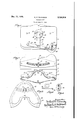
- Figure 1 is a view of the die in plan
- Fig. 2 is a view in underside plan
- Fig. 3 is a View in plan of a shoe upper vamp having marks thereon for the locations of a collar and. an imitation tip, respectively, two 5 smaller vamps in the series of the same style being shown in construction lines;
- Fig. 4 is a detail view in plan of the removable scale plate
- Fig. 5 is a detail view of the detent end of the slide operating arm.
- the die comprises two flat plates 6 (Fig. 1) and 1 (Fig. 2) secured together, back to back.
- the top of the plate 6 is provided with pins 8 and a disk 9 by means of which the die is connected detachably to the cross-head of the marking machine disclosed in my Patent No. 1,796,686, March 17, 1931 or my Patent No. 1,881,399, October 4, 1932, depending upon whether the blank to be marked is center or regular graded.
- the shoe upper blank I9 is provided with a mark I I forming a guide line for the location of a collar on the blank in a subsequent operatic-n and with a mark 12 forming guide lines for the location of an imitation tip on the blank.
- the mark H is made by a marker I3 (Fig. 2)
- the plate I5 is secured by the screws It to the plate 1 so that the plate 15, with its marker, may be removed readily as a unit from the plate 1 and replaced by another plate l5 having a marker l3 of different configuration thereon.
- the mark [2 is made by a marker ll projecting from a brass strip l8 secured to a flat plate l9.
- the plate [9 is secured by the screw 20 to a flat plate 2! so that the plate l9, with its marker, may be removed readily as a unit from the plate 2! and replaced by another plate l9 having a marker I! of different configuration.
- is secured to a slide22 (Fig. 1) received in a way 23 cut into the plate 6.
- the slide 22 slides beneath the plate 1, the slide being slotted (Fig. 2) to embrace loosely the screw [6.
- the movement of the slide is limited in both directions by lateral lugs 24 (Fig. 1) which engage shoulders 25 formed in the plate 6 by widening the way 23 adjacent its blind end.
- the cross-head When the die is inserted in either of the machines disclosed in my patents hereinbefore identified, the cross-head first is swung backward to press the markers l3 and I! against the ink pad and then the cross-head is swung forward to press the inked markers against the blank supported in the machine. If the markers Band I! are properly spaced apart the supported vamp l0 will receive the marks H and [2 in the correct location to act as guides in the subsequent application of the collar and imitation tip, respectively. If the next succeeding smaller sized vamp 26 (Fig. 3) in the series of upper blanks of the same style then is inserted in the machine and marked, it is apparent, from'an inspection ofFig. 3, that the mark l2 would be located too close to the toe end of the vamp 26 and too faraway from the throat thereof.
- the die is provided with means for shifting the marker l1 towards or away from the marker 13.
- the slide 22 carries a pin 21, (Fig. 1).
- the shank of the pin 21 is embraced by the walls of a slot 28 formed in an arm 29 one end of which is pivoted on a pin 30 projecting from the plate 6.
- the pins 21 and 30 are provided with heads, the shoulders of which engage the arm 29. Near its free end the arm 29 is provided with a fingerpiece 3
- the free end of the arm 29 is formed as a detent 32 (Fig. 5) which is pressed by the inherent elasticity of the arm 29 into one of a series of grooves 33 formed in a plate 34.
- the grooves, 33 are spaced apart a distance commensurate with the variation in tip heights between one size of vamp'and the next succeeding size.
- the plate 34 is provided with a scale indicating that the marker I! may be shifted to accommodate the marking of vamps varying in size from 2 to 9.
- the die is not limited for operation on vamps and may be used for making other fixed and graduated marks such as the fixed front mark and the graduated foxing mark on the quarters in a series of the same style.
- the graduation of the foxing mark is different from the graduation of the tip height, and so in order to prevent undue complication in the die to enable it to be accommodated to the different graduations, the plate 34 maybe removed as a unit and replaced by another plate. provided with differently spaced grooves 33 and bearing the same or perhaps a difierent scale.
- vamp ID (Fig. 3) is a No. 9 the detent 32 is engaged with the No. 9 groove 33 in the plate 34, thus insuring that whenthe markers l3 and I! are brought successively into engagement with the No. 9 vamps supported in the Edwards stitch marker, the collar and imitation tip guide lines will be located properly.
- the vamp 26 is a No. 8 and is to be marked next the detent 32 is disengaged from the No. 9 groove by pulling up on the finger-piece 3
- one part of all the blanks in the series of the same style and another part of only the blanks of the same size in said series may be marked in a uniform manner, provision for adjustment being made for moving the other part a predetermined distance towards or: away from the fixed marker to mark uniformly the corresponding other parts of the blanks of another size in the series of the same style.
- a die having, in combination, a support
- a marking member carried 'therebyymeans for adjusting the'marking member on its support including an inherently elastic arm carried by the support and provided with a detent, and a plate removably mounted on the support constructed tocooperate with the detent.
- a die having, in combination, a support, a scale plate removably mounted on the support, a marking member carried by the support, and means for adjusting the marking member on its support including an inherently elastic arm carried by the support and provided with a detent adapted to register with the scale on the plate.
- a die having, in combination, a support, a.
- a slide movable on the support a a plate supported by the slide, and a marker secured to the plate for placing a mark uniformly on only the blanks of the same size in the series, of means movable over the support for shifting the slide to position the second marker for placing a mark uniformly on only the blanks of another size in the series.
- a die for marking a series of shoe upper blanks of the same style the combination with a support, a marker secured thereto for placingv amark uniformly on all the blanks in the series, a slide movable on the support, a plate supported by the slide, and a marker secured to the plate for placing a mark uniformly on only the blanks of the same size in the series, of means movable over the support cooperating with means carried by the slide for shifting the slide to position the second marker for placing a mark uniformly on only the blanks of another size in the series.
- a die for marking a series of shoe upper blanks of the same style having, in combination, a support, a marker secured thereto for placin a mark uniformly on all the blanks in the series, a slide movable on the support, a plate supported by the slide, a marker secured to the plate for placing a mark uniformly on only the blanks of the same size in the series, said plate and the marker secured thereto being readily removable as a unit from the die, and means movable over the support for shifting the slide to position the second marker for placing a mark uniformly on only the blanks of another size in the series.
- a die for marking a series of shoe upper blanks of the same style having, in combination, a support, a plate carried thereby, a marker secured to the plate for placing a mark uniformly on all the blanks in the series, a slide movable on the support, a plate supported by the slide, a marker secured to the plate for placing a mark uniformly on only the blanks of the same size in the series, at least one of said plates and the marker secured thereto being readily removable as a unit from the die, and means movable over the support for shifting the slide to position the second marker for placing 20 a mark uniformly on only the blanks of another size in the series.
Landscapes
- Footwear And Its Accessory, Manufacturing Method And Apparatuses (AREA)
Description
Dec. 17, 1935. H E EDWARDS 2,024,916
MARKING DIE Filed June 9, 1932 Java 2360:
Patented Dec. 17, 1935 UNITED STATES PATENT OFFICE MARKING DIE Herbert E. Edwards, Brookline, Mass.
Application June 9, 1932, Serial No. 616,262
'7 Claims. (Cl. 101-373) The present invention relates to marking devices which are used in the manufacture of shoes to mark upper blanks, such as vamps, tips, quarters, foxing and straps, with lines for 5 use as guides in subsequent hand and machine operations. The guide lines may indicate the center lines of the blanks, the lap of one blank over an adjacent blank, or the location of collars, imitationtips, overlays, underlays, perfora- 1 tions, embossings, ornamental cut-outs and stitches.
Shoe upper blanks in a series of the different sizes and widths of the same style, which have a common portion of their peripheries held to 15 the same grade, are called center graded to distinguish them from regular graded upper blanks, the peripheries of which have no common portion of any extent. In marking these shoe upper blanks, both center and regular graded, it is 20 often desirable to place two spaced marks thereon, one of which is fixed for all the blanks in the series and the other one of which is varied in accordance with'the size of the blank, the second mark being fixed for only the blanks of 25 the same size in the series. One instance of this occurs in the marking of quarters, the front mark being fixed and the rear mark being varied as the length of the quarter varies in order to locate the front edges of the foxing the proper distance for the size of the shoe from the rear end thereof. Another instance occurs in the marking of vamps, the rear mark being fixed to locate a collar, for instance, adjacent the throat'uniformly for all the blanks in the series and the front mark being varied to locate an imitation tip, for instance, the proper distance for the size of the shoe from the front end thereof.
The principal object of the present invention 40 is to provide a single die for producing spaced marks throughout a series of shoe upper blanks of the same style.
To the accomplishment of this object, and such others as may appear hereinafter, the various features of the present invention reside in certain devices, combinations and arrangements of parts hereinafter described and then set forth broadly and in detail in the appended claims which possess advantages readily apparent to those skilled in the art.
The various features of the present invention will be readily understood from an inspection of the accompanying drawing illustrating the best form of the invention at present known to 55 the inventor, in which,
Figure 1 is a view of the die in plan;
Fig. 2 is a view in underside plan;
Fig. 3 is a View in plan of a shoe upper vamp having marks thereon for the locations of a collar and. an imitation tip, respectively, two 5 smaller vamps in the series of the same style being shown in construction lines;
Fig. 4 is a detail view in plan of the removable scale plate, and
Fig. 5 is a detail view of the detent end of the slide operating arm.
In the illustrated embodiment of the invention, the die comprises two flat plates 6 (Fig. 1) and 1 (Fig. 2) secured together, back to back. The top of the plate 6 is provided with pins 8 and a disk 9 by means of which the die is connected detachably to the cross-head of the marking machine disclosed in my Patent No. 1,796,686, March 17, 1931 or my Patent No. 1,881,399, October 4, 1932, depending upon whether the blank to be marked is center or regular graded.
Referring to Fig. 3, the shoe upper blank I9 is provided with a mark I I forming a guide line for the location of a collar on the blank in a subsequent operatic-n and with a mark 12 forming guide lines for the location of an imitation tip on the blank.
The mark H is made by a marker I3 (Fig. 2)
' projecting from one edge of a pair of brass strips 14 secured to a fiat plate IS. The plate I5 is secured by the screws It to the plate 1 so that the plate 15, with its marker, may be removed readily as a unit from the plate 1 and replaced by another plate l5 having a marker l3 of different configuration thereon.
The mark [2 is made by a marker ll projecting from a brass strip l8 secured to a flat plate l9. The plate [9 is secured by the screw 20 to a flat plate 2! so that the plate l9, with its marker, may be removed readily as a unit from the plate 2! and replaced by another plate l9 having a marker I! of different configuration.
The plate 2| is secured to a slide22 (Fig. 1) received in a way 23 cut into the plate 6. The slide 22 slides beneath the plate 1, the slide being slotted (Fig. 2) to embrace loosely the screw [6. The movement of the slide is limited in both directions by lateral lugs 24 (Fig. 1) which engage shoulders 25 formed in the plate 6 by widening the way 23 adjacent its blind end.
When the die is inserted in either of the machines disclosed in my patents hereinbefore identified, the cross-head first is swung backward to press the markers l3 and I! against the ink pad and then the cross-head is swung forward to press the inked markers against the blank supported in the machine. If the markers Band I! are properly spaced apart the supported vamp l0 will receive the marks H and [2 in the correct location to act as guides in the subsequent application of the collar and imitation tip, respectively. If the next succeeding smaller sized vamp 26 (Fig. 3) in the series of upper blanks of the same style then is inserted in the machine and marked, it is apparent, from'an inspection ofFig. 3, that the mark l2 would be located too close to the toe end of the vamp 26 and too faraway from the throat thereof.
Stated in another way, if each vamp in the series of upper blanks of the same style is considered as being provided with a tip line, the tip heightsthat is, the distance between the feet of the lead'lines A and B (Fig. 3) vary uniformly as the vamps in the'series decrease in size. It follows therefore that if the mark I2 is located properly at the tip line on the vamp ID the mark I 2 will miss the tip line on the vamp 26 by the difference between the tip height on the vamp l0 and the tip height on the vamp 26.
In order to correlate the markers to compensate for the variation in tip heights on the vamps of diiferent sizes, the die is provided with means for shifting the marker l1 towards or away from the marker 13. To this end the slide 22 carries a pin 21, (Fig. 1). The shank of the pin 21 is embraced by the walls of a slot 28 formed in an arm 29 one end of which is pivoted on a pin 30 projecting from the plate 6. The pins 21 and 30 are provided with heads, the shoulders of which engage the arm 29. Near its free end the arm 29 is provided with a fingerpiece 3| by means of which the arm 29 may be swungon its pivot to operate the slide 22.
In order to hold the slide 22 in its desired position of adjustment the free end of the arm 29 is formed as a detent 32 (Fig. 5) which is pressed by the inherent elasticity of the arm 29 into one of a series of grooves 33 formed in a plate 34.
The grooves, 33 are spaced apart a distance commensurate with the variation in tip heights between one size of vamp'and the next succeeding size. As shown in Fig. 1 the plate 34 is provided with a scale indicating that the marker I! may be shifted to accommodate the marking of vamps varying in size from 2 to 9.
While this tip height variation is practically uniform throughout the industry the die is not limited for operation on vamps and may be used for making other fixed and graduated marks such as the fixed front mark and the graduated foxing mark on the quarters in a series of the same style. The graduation of the foxing mark is different from the graduation of the tip height, and so in order to prevent undue complication in the die to enable it to be accommodated to the different graduations, the plate 34 maybe removed as a unit and replaced by another plate. provided with differently spaced grooves 33 and bearing the same or perhaps a difierent scale.
If the vamp ID (Fig. 3) is a No. 9 the detent 32 is engaged with the No. 9 groove 33 in the plate 34, thus insuring that whenthe markers l3 and I! are brought successively into engagement with the No. 9 vamps supported in the Edwards stitch marker, the collar and imitation tip guide lines will be located properly. If the vamp 26 is a No. 8 and is to be marked next the detent 32 is disengaged from the No. 9 groove by pulling up on the finger-piece 3| which is then moved to shift the slide 22 and correlate the markers I 3 and I! in accordance with the size of the vamp 26, the detent 32. being placed in the No. 8 groove in the plate 34. This insures that. the vamp 26 will be provided with the marks II and Rat the collar and tip line, respectively.
By use of the illustrated embodiment of the present invention in the Edwards marking machine, one part of all the blanks in the series of the same style and another part of only the blanks of the same size in said series may be marked in a uniform manner, provision for adjustment being made for moving the other part a predetermined distance towards or: away from the fixed marker to mark uniformly the corresponding other parts of the blanks of another size in the series of the same style. m
Nothing herein explained is to be interpreted as limiting the invention in the scope of its application to use in marking any particular type of shoe upper blank in connection with the particular marking machine or the particular mode of operation or both selected for purposes of illustration and explanation. the particulars of construction herein set forth are well suited to one structural form of the invention, it is not limited to these details of construction, nor to the conjoint use of all its features, nor is it to be understood that these particulars are essential since they may be modified within the skill of the artisan without departing from the true scope of the actual invention, characterizing features of which are set forth in the following claims by the intentional use of generic terms and expressions, inclusive of various modifications.
What is claimed as new is: I
1. A die having, in combination, a support,
While a marking member carried 'therebyymeans for adjusting the'marking member on its support including an inherently elastic arm carried by the support and provided with a detent, and a plate removably mounted on the support constructed tocooperate with the detent.
2. A die having, in combination, a support, a scale plate removably mounted on the support, a marking member carried by the support, and means for adjusting the marking member on its support including an inherently elastic arm carried by the support and provided with a detent adapted to register with the scale on the plate.
3. A die having, in combination, a support, a.
the series, a slide movable on the support. a a plate supported by the slide, and a marker secured to the plate for placing a mark uniformly on only the blanks of the same size in the series, of means movable over the support for shifting the slide to position the second marker for placing a mark uniformly on only the blanks of another size in the series.
5. In a die for marking a series of shoe upper blanks of the same style, the combination with a support, a marker secured thereto for placingv amark uniformly on all the blanks in the series, a slide movable on the support, a plate supported by the slide, and a marker secured to the plate for placing a mark uniformly on only the blanks of the same size in the series, of means movable over the support cooperating with means carried by the slide for shifting the slide to position the second marker for placing a mark uniformly on only the blanks of another size in the series.
6. A die for marking a series of shoe upper blanks of the same style having, in combination, a support, a marker secured thereto for placin a mark uniformly on all the blanks in the series, a slide movable on the support, a plate supported by the slide, a marker secured to the plate for placing a mark uniformly on only the blanks of the same size in the series, said plate and the marker secured thereto being readily removable as a unit from the die, and means movable over the support for shifting the slide to position the second marker for placing a mark uniformly on only the blanks of another size in the series.
'7. A die for marking a series of shoe upper blanks of the same style having, in combination, a support, a plate carried thereby, a marker secured to the plate for placing a mark uniformly on all the blanks in the series, a slide movable on the support, a plate supported by the slide, a marker secured to the plate for placing a mark uniformly on only the blanks of the same size in the series, at least one of said plates and the marker secured thereto being readily removable as a unit from the die, and means movable over the support for shifting the slide to position the second marker for placing 20 a mark uniformly on only the blanks of another size in the series.
HERBERT E. EDWARDS.
Priority Applications (1)
| Application Number | Priority Date | Filing Date | Title |
|---|---|---|---|
| US616262A US2024916A (en) | 1932-06-09 | 1932-06-09 | Marking die |
Applications Claiming Priority (1)
| Application Number | Priority Date | Filing Date | Title |
|---|---|---|---|
| US616262A US2024916A (en) | 1932-06-09 | 1932-06-09 | Marking die |
Publications (1)
| Publication Number | Publication Date |
|---|---|
| US2024916A true US2024916A (en) | 1935-12-17 |
Family
ID=24468682
Family Applications (1)
| Application Number | Title | Priority Date | Filing Date |
|---|---|---|---|
| US616262A Expired - Lifetime US2024916A (en) | 1932-06-09 | 1932-06-09 | Marking die |
Country Status (1)
| Country | Link |
|---|---|
| US (1) | US2024916A (en) |
-
1932
- 1932-06-09 US US616262A patent/US2024916A/en not_active Expired - Lifetime
Similar Documents
| Publication | Publication Date | Title |
|---|---|---|
| US2024916A (en) | Marking die | |
| US1689633A (en) | Apparatus for manufacturing ornamented shoe uppers | |
| US2657463A (en) | Foot-measuring machine | |
| US2711704A (en) | Seam guide for sewing machines | |
| US2090824A (en) | Marking die | |
| US2013679A (en) | Shoe part ornamenting machine | |
| US1890714A (en) | Gauge | |
| US1358794A (en) | Sole-measuring machine | |
| US3392691A (en) | Dart gauge | |
| US2056117A (en) | Shoe-element marking device | |
| US1341312A (en) | Gage for perforating-machines | |
| US2078569A (en) | Adjustable die and blade for the same | |
| US3176401A (en) | Shoe manufacturing gauge | |
| US846153A (en) | Counting device for blank-cutting machines. | |
| US2111815A (en) | Machine for copying contours | |
| US1493950A (en) | Apparatus for locating shank stiffeners in shoe soles | |
| US1134966A (en) | Buttonhole spacer and marker for buttonhole-machines. | |
| US2242473A (en) | Machine for operating on sole members | |
| US1985311A (en) | Manufacture of shoes | |
| US2594470A (en) | Machine for applying ribbed strips to orthopedic insoles | |
| US2059344A (en) | Machine for operating upon sheet materials | |
| US2744330A (en) | Marking instrument | |
| US2097363A (en) | Die | |
| US2633967A (en) | Decimal indicator and marking guide | |
| US1191965A (en) | Machine for marking shoe-uppers. |