US2024914A - Cutter for beveled gears - Google Patents
Cutter for beveled gears Download PDFInfo
- Publication number
- US2024914A US2024914A US19085A US1908535A US2024914A US 2024914 A US2024914 A US 2024914A US 19085 A US19085 A US 19085A US 1908535 A US1908535 A US 1908535A US 2024914 A US2024914 A US 2024914A
- Authority
- US
- United States
- Prior art keywords
- cutters
- blank
- chamber
- sections
- barrel
- Prior art date
- Legal status (The legal status is an assumption and is not a legal conclusion. Google has not performed a legal analysis and makes no representation as to the accuracy of the status listed.)
- Expired - Lifetime
Links
- 238000010276 construction Methods 0.000 description 2
- 238000003801 milling Methods 0.000 description 2
- 238000007689 inspection Methods 0.000 description 1
- 230000014759 maintenance of location Effects 0.000 description 1
- 230000000717 retained effect Effects 0.000 description 1
- 230000036346 tooth eruption Effects 0.000 description 1
Images
Classifications
-
- B—PERFORMING OPERATIONS; TRANSPORTING
- B23—MACHINE TOOLS; METAL-WORKING NOT OTHERWISE PROVIDED FOR
- B23F—MAKING GEARS OR TOOTHED RACKS
- B23F21/00—Tools specially adapted for use in machines for manufacturing gear teeth
- B23F21/12—Milling tools
-
- B—PERFORMING OPERATIONS; TRANSPORTING
- B23—MACHINE TOOLS; METAL-WORKING NOT OTHERWISE PROVIDED FOR
- B23F—MAKING GEARS OR TOOTHED RACKS
- B23F23/00—Accessories or equipment combined with or arranged in, or specially designed to form part of, gear-cutting machines
- B23F23/12—Other devices, e.g. tool holders; Checking devices for controlling workpieces in machines for manufacturing gear teeth
- B23F23/1237—Tool holders
-
- Y—GENERAL TAGGING OF NEW TECHNOLOGICAL DEVELOPMENTS; GENERAL TAGGING OF CROSS-SECTIONAL TECHNOLOGIES SPANNING OVER SEVERAL SECTIONS OF THE IPC; TECHNICAL SUBJECTS COVERED BY FORMER USPC CROSS-REFERENCE ART COLLECTIONS [XRACs] AND DIGESTS
- Y10—TECHNICAL SUBJECTS COVERED BY FORMER USPC
- Y10T—TECHNICAL SUBJECTS COVERED BY FORMER US CLASSIFICATION
- Y10T409/00—Gear cutting, milling, or planing
- Y10T409/10—Gear cutting
- Y10T409/107791—Using rotary cutter
- Y10T409/108586—Plural rotary cutters
Definitions
- This invention relates to an improved device for cutting beveled gears and one object of the invention is to provide a device of this character which is so constructed that blanks may be fed into body or barrel of the device and a set of teeth of the same depth and pitch cut in the blank about margins thereof at vthe same time.
- Another object of the invention is to provide improved means for carrying the blank and feeding the same towards cutters carried by the barrel and to also provide means for limiting movement of the blank towards the cutters which is adjustably mounted so that teeth of a desired depth may be formed.
- Another object of the invention is to provide a gear cutter wherein the barrel is formed in separable sections between abutting ends of which the cutters are rotatably mounted, thereby allowing the cutters to be easily removed for sharpening or replacement and insuring retention of the cutters in their proper positions when the sections of the barrel are secured to each other.
- Another object of the invention is to so mount the cutters that rotary motion imparted from a rotatably mounted power shaft may be transmitted from one cutter to another by gears interposed between the cutters, the gears being mounted in bearing brackets which serve not only as means for rotatably mounting the gears but also as means for holding the sections of the barrel in end to end relation to each other.
- a further object of the invention is to provide a. device of this character which is simple in construction, strong and durable, and not liable to get out of order.
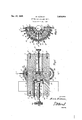
- Figure 1 is a longitudinal section through the improved gear cutter.
- Figure 2 is a View in elevation with one section of the barrel removed.
- This improved cutter has a body or barrel consisting of companion sections I and 2, which are disposed in end to end relation to each other, with the inner end of the section I extended about its center to form an axially eX- tending annular extension 3, which is snugly received in a recess 4 formed in the inner end face of the section 2.
- Heads or closure disks 5 and 6 are provided for outer ends of the two sections, which are secured vby machine screws I and 8.
- the head is also formed with openings registering with openings formed through the section 2 whereby bolts 9 may be passed i through the section 2 and threaded into sockets I formed in the hub or extension 3 of the section I and securely but detachably hold the sections in engagement with each other.
- the section 2 is also formed with a bore or chamber I4 and it will be noted that 20 the inner end portion of the chamber i3 tapered as shown and I5 terminates in a reduced extension I6 which corresponds in diameter to the chamber I4 of the section 2 and registers With the inner end thereof.
- Rotary motion is to be imparted to the cutters, and in order to do so there has been provided a drive shaft I'I which may be rotated from any suitable source of power.
- This drive shaft has one end rotatably mounted through a bearing bracket I8 extending longitudinally of the barrel in bridging relation to the sections thereof, and by referring to Figure 2, it will be seen that the bracket serves not only as means for rotatably mounting the shaft but also as means for connecting the sections of the barrel and retaining them in end to end relation tol each other.
- a gear or pinion I9 is carried by the drive shaft and meshes with gear rings formed upon side faces of cutters between which 4Q the gear is located.
- the blank from which a gear 23 is to be formed is mounted in the chamber I3 of the closure 5 so that when the knob 28 at the outer end of the'shank is grasped and rotary motion imparted thereto, the carrier will be shifted longitudinally in the chamber according to the direction in which the shaft is rotated.
- Rods 29 which project from the carrier through openings formed in the head 5, prevent the carrier from turning with the shank.
- Means has been provided for controlling inward movement of the blank consisting of a shaft 3l threaded through a bearing 32 formed at the center of the head 6.
- This shaft which may be referred to as an adjustable abutment, has a head 33 at its inner end for engagement by the central portion of the blank and at its outer end carries a turning knob 34, by means of which it can be rotated and shifted longitudinally in the chamber I4.
- Gauge markings may be formed upon 'the shaft 3l to indicate the extent to which the head ⁇ 33 projects into the chamber I3 and thereby permit the abutment to be accurately set.
- the bolts which ysecure the brackets are removed, thus allowing the section 2 to be shifted away from the section herein is particularly adapted for cutting beveled gears it is to be understood that by manipulating the proper gear blank it may be used for cutting straight gears and is not limited to use in cutting beveled gears.
- a barrel having companion sections disposed in end to end relation to each other and formed with registering bores defining aligned chambers in the sections, one of said chambers for receivingthe blank to be operated upon and being formed at its inner part with a tapered portion terminating in a reduced portion of uniform diameter, the other of said chambers corresponding in diameter to and opening at 15 its innerend in said reduced portion, adjoining ends of the sections being formed with registering grooves defining pockets opening into the said tapered portion, the opposed ends of said sections having registering recesses, cutters in said pock- 20 ets having shafts rotatably mounted in said recesses ⁇ and provided with gear rings at their sides and having successive parts extended into 'said tapered portion, brackets bridging thesections between the cutters and securing the sec- 25 tions to each other, gears rotatably carried by said brackets and meshing with gear rings for transmitting rotary motion from the cutters to each other, a carrier in the blank receiving chamber mounted for
- a gear cutter In a gear cutter, a barrel having a main chamber and an auxiliary chamberl aligned therewith and opening thereinto, cutters vrotat- 55.;
- an adjustable rod threaded through an opening formed in the head of the auxiliary chamber and having its inner end portion projecting into the main chamber andconstituting an adjustable abutment for engaginga blank held by the carrier for limiting movement of the blank towards the cutters.
Landscapes
- Engineering & Computer Science (AREA)
- Mechanical Engineering (AREA)
- Details Of Cutting Devices (AREA)
Description
Dec. 17, 1935. M- DRMAN 2,024,914
CUTTER FOR BEVELED GEARS Filed April.l 30, 1955 Patented Dec. 17, 1935 UNITED STATES PATENT OFFICEv 3 Claims.
This invention relates to an improved device for cutting beveled gears and one object of the invention is to provide a device of this character which is so constructed that blanks may be fed into body or barrel of the device and a set of teeth of the same depth and pitch cut in the blank about margins thereof at vthe same time.
Another object of the invention is to provide improved means for carrying the blank and feeding the same towards cutters carried by the barrel and to also provide means for limiting movement of the blank towards the cutters which is adjustably mounted so that teeth of a desired depth may be formed.
Another object of the invention is to provide a gear cutter wherein the barrel is formed in separable sections between abutting ends of which the cutters are rotatably mounted, thereby allowing the cutters to be easily removed for sharpening or replacement and insuring retention of the cutters in their proper positions when the sections of the barrel are secured to each other.
Another object of the invention is to so mount the cutters that rotary motion imparted from a rotatably mounted power shaft may be transmitted from one cutter to another by gears interposed between the cutters, the gears being mounted in bearing brackets which serve not only as means for rotatably mounting the gears but also as means for holding the sections of the barrel in end to end relation to each other.
A further object of the invention is to provide a. device of this character which is simple in construction, strong and durable, and not liable to get out of order.
The invention is illustrated in the accompanying drawing wherein:
Figure 1 is a longitudinal section through the improved gear cutter.
Figure 2 is a View in elevation with one section of the barrel removed.
This improved cutter has a body or barrel consisting of companion sections I and 2, which are disposed in end to end relation to each other, with the inner end of the section I extended about its center to form an axially eX- tending annular extension 3, which is snugly received in a recess 4 formed in the inner end face of the section 2. Heads or closure disks 5 and 6 are provided for outer ends of the two sections, which are secured vby machine screws I and 8. The head is also formed with openings registering with openings formed through the section 2 whereby bolts 9 may be passed i through the section 2 and threaded into sockets I formed in the hub or extension 3 of the section I and securely but detachably hold the sections in engagement with each other.
Radially extending slots or grooves are formed in the inner end portions of the sections i and 2 which register when the sections are secured in abutting engagement with each other and define pockets to receive milling cutters Ii, the r of the section I open into the bore or central 16;
chamber I3 extending axially through the same, and that portions of the milling disks or cutters project into the chamber for cutting teeth in a gear blank. The section 2 is also formed with a bore or chamber I4 and it will be noted that 20 the inner end portion of the chamber i3 tapered as shown and I5 terminates in a reduced extension I6 which corresponds in diameter to the chamber I4 of the section 2 and registers With the inner end thereof. Y
Rotary motion is to be imparted to the cutters, and in order to do so there has been provided a drive shaft I'I which may be rotated from any suitable source of power. This drive shaft has one end rotatably mounted through a bearing bracket I8 extending longitudinally of the barrel in bridging relation to the sections thereof, and by referring to Figure 2, it will be seen that the bracket serves not only as means for rotatably mounting the shaft but also as means for connecting the sections of the barrel and retaining them in end to end relation tol each other. A gear or pinion I9 is carried by the drive shaft and meshes with gear rings formed upon side faces of cutters between which 4Q the gear is located. Other gears 2| are located between the remaining cutters in mesh with gear rings forming upon sides thereof, and referring to Figure 2, it will be seen that each gear is rotatably mounted in a bracket 22 having the same construction as the bracket I8. 'Ihese brackets 22 are also secured in bridging relation to the sections of the barrel and when the brackets I8 and 22 are secured the two, sections will be firmly held united and also the cutters will be retained in the pockets formed in the sections and be freely rotatable. It will be readily apparent from an inspection of Figure 2 that when the drive shaft is rotated, rotary motion will be imparted to the cutters with 55 Vtowards the inner end of the chamber.
which the gear I9 meshes and that rotary motion will be transmitted from one cutter to another through the gears 2|. Therefore, all of the cutters will be positively driven.
The blank from which a gear 23 is to be formed is mounted in the chamber I3 of the closure 5 so that when the knob 28 at the outer end of the'shank is grasped and rotary motion imparted thereto, the carrier will be shifted longitudinally in the chamber according to the direction in which the shaft is rotated. Rods 29 which project from the carrier through openings formed in the head 5, prevent the carrier from turning with the shank. It will thus be seen that when the blank is fitted into the socket of the carrier and secured bytightening the set screws 30, the carrier and blank can be thrust into the chamber I3. The head 5 is then secured by its Vbolts I and the shank or shaft 26 then rotated to move the blank through the chamber towards the inwardly projecting portions of the cutters. As. the| blank is moved towards the cutters, they cut into the marginal portions thereof to form the teeth, the depth of which is controlled bythe distance the blank is moved Means has been provided for controlling inward movement of the blank consisting of a shaft 3l threaded through a bearing 32 formed at the center of the head 6. This shaft, which may be referred to as an adjustable abutment, has a head 33 at its inner end for engagement by the central portion of the blank and at its outer end carries a turning knob 34, by means of which it can be rotated and shifted longitudinally in the chamber I4. Proper adjustment of the abutment shaft will cause it to project into the tapered inner end portion of the chamber I3 a r predetermined distance and as the blank will be held against further inward movement when it engages the head 33 of the abutment shaft, the teeth formed in the blank will onlyfbe of a dej sired depth. After the teeth have been formed in the blank, it is merely necessary to turn the shank 26 in a direction to shift the carrier and 'blank away from the cutters and the bolts 1 can then be removed to release the head 5 and ,permit the carrier and blank to be withdrawn from the chamber and the formed gear removed from the carrier. l
Gauge markings may be formed upon 'the shaft 3l to indicate the extent to which the head `33 projects into the chamber I3 and thereby permit the abutment to be accurately set. When it is necessary to clean the device or sharpen 'or' replace any of the cutters, the bolts which ysecure the brackets are removed, thus allowing the section 2 to be shifted away from the section herein is particularly adapted for cutting beveled gears it is to be understood that by manipulating the proper gear blank it may be used for cutting straight gears and is not limited to use in cutting beveled gears.
Having thus described the invention, what is claimed is:
1. In a gear cutter, a barrel having companion sections disposed in end to end relation to each other and formed with registering bores defining aligned chambers in the sections, one of said chambers for receivingthe blank to be operated upon and being formed at its inner part with a tapered portion terminating in a reduced portion of uniform diameter, the other of said chambers corresponding in diameter to and opening at 15 its innerend in said reduced portion, adjoining ends of the sections being formed with registering grooves defining pockets opening into the said tapered portion, the opposed ends of said sections having registering recesses, cutters in said pock- 20 ets having shafts rotatably mounted in said recesses `and provided with gear rings at their sides and having successive parts extended into 'said tapered portion, brackets bridging thesections between the cutters and securing the sec- 25 tions to each other, gears rotatably carried by said brackets and meshing with gear rings for transmitting rotary motion from the cutters to each other, a carrier in the blank receiving chamber mounted for advancing a gear blank 3()A ters rotatably mounted between adjoining ends 401 of said-sections and having gear rings at their sides engaging said gears whereby l'the cutters will be driven one from another, means extended from said barrel and connected to one yof said gears for driving it, said cutters projecting 45,5
into the main .section of the barrel in proximity to the inner end of said main section, adjustable means for supporting agear blank in the main section in operative relation to. the cutters, and
adjustable means carried by the auxiliary section 50i:
for limiting movement of the blank towards the cutters. l
3. In a gear cutter, a barrel having a main chamber and an auxiliary chamberl aligned therewith and opening thereinto, cutters vrotat- 55.;
ablymounted in and lprojecting throughi the body of the barrel into the main chamber, in proximity to the inner end ofthe latter, heads for outer ends of said chambers, an adjustable carrier slidable through 'the main chamberfor @0i presenting a blank to the cutters, a threaded shank for and swivelly connected to 'said carrier engaged through a threaded bearing on the head for the main chamber, stems extending` fromithe carrier and throughV the head of the main 651.
chamber to prevent rotation of the carrier, and an adjustable rod threaded through an opening formed in the head of the auxiliary chamber and having its inner end portion projecting into the main chamber andconstituting an adjustable abutment for engaginga blank held by the carrier for limiting movement of the blank towards the cutters.
MORRIS DQRMAN.
Priority Applications (1)
| Application Number | Priority Date | Filing Date | Title |
|---|---|---|---|
| US19085A US2024914A (en) | 1935-04-30 | 1935-04-30 | Cutter for beveled gears |
Applications Claiming Priority (1)
| Application Number | Priority Date | Filing Date | Title |
|---|---|---|---|
| US19085A US2024914A (en) | 1935-04-30 | 1935-04-30 | Cutter for beveled gears |
Publications (1)
| Publication Number | Publication Date |
|---|---|
| US2024914A true US2024914A (en) | 1935-12-17 |
Family
ID=21791336
Family Applications (1)
| Application Number | Title | Priority Date | Filing Date |
|---|---|---|---|
| US19085A Expired - Lifetime US2024914A (en) | 1935-04-30 | 1935-04-30 | Cutter for beveled gears |
Country Status (1)
| Country | Link |
|---|---|
| US (1) | US2024914A (en) |
-
1935
- 1935-04-30 US US19085A patent/US2024914A/en not_active Expired - Lifetime
Similar Documents
| Publication | Publication Date | Title |
|---|---|---|
| US1953402A (en) | Tool for boring and facing cylinders and the like | |
| US2373472A (en) | Rotary cutter structure | |
| GB1401916A (en) | Precision boring and smooth rolling apparatus | |
| US2451447A (en) | Hobbing machine | |
| US2024914A (en) | Cutter for beveled gears | |
| US2276727A (en) | Boring and pipe cutting machine | |
| US2991667A (en) | Boring tool | |
| US1941598A (en) | Machine for turning and grinding | |
| SU759243A1 (en) | Cutting mill | |
| US1053482A (en) | Pipe-threader. | |
| US1029265A (en) | Pipe-cutting tool. | |
| US1140610A (en) | Method of and apparatus for cutting the teeth of gear-wheels. | |
| US627074A (en) | conway | |
| US1034927A (en) | Device for setting cutters. | |
| US1771534A (en) | Automatic or other nut-making and like machine tool | |
| US2325849A (en) | Steady rest for lathes | |
| DE524949C (en) | Milling head with blades adjustable in the radial direction by means of a plane thread | |
| US1153241A (en) | Turning or boring appliance. | |
| US1539364A (en) | Turning machine | |
| US1392203A (en) | Adjustable boring-tool | |
| US1867161A (en) | Gear cutter | |
| US1687260A (en) | Machine for making helically-grooved actuating members for steering gears | |
| CH420798A (en) | Process for producing gears on a hobbing machine and gear hobbing machine for carrying out the process | |
| US1343503A (en) | Metal-working machine | |
| US1232296A (en) | Thread-milling fixture. |