US2024910A - Container - Google Patents
Container Download PDFInfo
- Publication number
- US2024910A US2024910A US735028A US73502834A US2024910A US 2024910 A US2024910 A US 2024910A US 735028 A US735028 A US 735028A US 73502834 A US73502834 A US 73502834A US 2024910 A US2024910 A US 2024910A
- Authority
- US
- United States
- Prior art keywords
- container
- holder
- drawings
- further modification
- view
- Prior art date
- Legal status (The legal status is an assumption and is not a legal conclusion. Google has not performed a legal analysis and makes no representation as to the accuracy of the status listed.)
- Expired - Lifetime
Links
- 230000004048 modification Effects 0.000 description 12
- 238000012986 modification Methods 0.000 description 12
- 230000035622 drinking Effects 0.000 description 7
- 238000010276 construction Methods 0.000 description 4
- 239000007788 liquid Substances 0.000 description 4
- 235000013405 beer Nutrition 0.000 description 1
- 239000010687 lubricating oil Substances 0.000 description 1
- 238000004519 manufacturing process Methods 0.000 description 1
- 239000002184 metal Substances 0.000 description 1
- 238000000926 separation method Methods 0.000 description 1
Images
Classifications
-
- B—PERFORMING OPERATIONS; TRANSPORTING
- B65—CONVEYING; PACKING; STORING; HANDLING THIN OR FILAMENTARY MATERIAL
- B65D—CONTAINERS FOR STORAGE OR TRANSPORT OF ARTICLES OR MATERIALS, e.g. BAGS, BARRELS, BOTTLES, BOXES, CANS, CARTONS, CRATES, DRUMS, JARS, TANKS, HOPPERS, FORWARDING CONTAINERS; ACCESSORIES, CLOSURES, OR FITTINGS THEREFOR; PACKAGING ELEMENTS; PACKAGES
- B65D23/00—Details of bottles or jars not otherwise provided for
Definitions
- the invention relates to containers and more especially to metallic liquid containers.
- the primary object of the invention is the provision of a container of this character, wherein either the top or bottom thereof can be removed, so that the container will function for dispensing liquid or for a drinking receptacle, and also the removable bottom when detached will serve as a holder for the container.
- Another object of the invention is the provision of a container of this character, wherein the construction thereof is novel in form and is convertible for the storage of liquid to a drinking receptacle, thus making the same handy for use in the dispensing of sodas, beer, lubricating oil or the like.
- a further object of the invention is the provision of a container of this character which is simple in construction, thoroughly reliable and effective for its purposes, strong, durable, and inexpensive to manufacture.
- Figure 1 is a vertical longitudinal sectional view of a container constructed in accordance with the invention, the same being broken away for a distance of its length.
- Fig. 2 is a view similar to Figure 1 showing the container converted for drinking purposes and supported in a holder when at rest.
- Figure 3 is a view similar to Figure 1 showing a slight modification.
- Figure 4 is a view similar to Figure 3 showing a further modification.
- Figure 5 is a view similar to Figure 4 showing the container! inverted and supported in the holder therefor.
- Figure 6 is a fragmentary vertical sectional view of a further modification.
- Figure 7 is a view similar to Figure 5 showing another modification.
- Figure 8 is a view similar to Figure 1 showing a still further modification.
- Figure 9 is a bottom plan view.
- Figure 10 is a side elevation partly in section of a further modified form of container.
- Figure 11 is a sectional view on the line I l--
- Figure 12 is a fragmentary side elevation of a still further modification of container.
- the container therein shown comprises a conical-shaped body l0, preferably made from sheet metal, and at the smaller end of this body is a removable top II which is 10 in the nature of a cap having an interlocking seam edge l2 with the body, while at the other or wider end of the said body is an inset bottom l3 having the interlocked seam edge 14 with said body.
- a holder Interiorly of the body l0 and super- 15 imposed upon the bottom I3 is a holder having the flared or upwardly tapered base portion l5 and the rim I6.
- the holder is removed from the body l0 by severing the bottom l3 in a circular path concentric to the portion I5 of the holder, it being understood, of course, that the said body I0 is inverted from the position shown in Figure 1 to avoid the loss of its contents and thereafter the holder is placed upon a support and the smaller end of the body In is telescoped into the rim N5 of said holder, whereby the container will be supported in a position for drinking purposes.
- the bottom IT has the inner and outer annular flanged walls I 8 and I9, respectively, these being spaced apart to provide a clearance therebetween, so that the said bottom I1 may be cut at the fold 20 therein to release the holder 2
- bottom 22 constitutes a holder when severed from the body 23 following the fold 24 in said bottom and such holder, centrally thereof, is formed with a cupshaped socket 25 for accommodating the smaller end of the body 23 of the container when inverted to this position.
- the holder is also inverted to accommodate the smaller end of the body 23, as is shown in Figure 5 of the drawings.
- the container under the various forms of construction, can be utilized for dispensing liquids and also as a drinking receptacle and when used as a drinking receptacle can be held in a holder when at rest, the holder either being a part of or independent from the said container.
- a container of the character described comprising a bottle-like body, closure members lock seamed with opposite ends of said body, one of said closure members constituting a supporting base on separation thereof from the body, and a cup formed with the closure member constituting the base for telescopically receiving an end of the body when the latter has been separated from the closure member constituting said base for the holding of the said body in a perpendicular upstanding position when in the cup.
Landscapes
- Engineering & Computer Science (AREA)
- Mechanical Engineering (AREA)
- Details Of Rigid Or Semi-Rigid Containers (AREA)
Description
Dec. 17, 1935. L, w. CRAMER CONTAINER Filed July 13, 193 1 2 Sheets-Sheet l INVENTOR Z ou i/s E. drama?" ATTORNEY Dec. 17, 1935. L. w. CRAMER CONTAINER Filed July 13, 1934 2 Sheets-Sheet 2 low 7L5 W, drama? INVENTOR ATTO R N EY Patented Dec. 17, 1935 UNITED STATES PATENT OFFICE v 1 Claim.
The invention relates to containers and more especially to metallic liquid containers.
The primary object of the invention is the provision of a container of this character, wherein either the top or bottom thereof can be removed, so that the container will function for dispensing liquid or for a drinking receptacle, and also the removable bottom when detached will serve as a holder for the container.
Another object of the invention is the provision of a container of this character, wherein the construction thereof is novel in form and is convertible for the storage of liquid to a drinking receptacle, thus making the same handy for use in the dispensing of sodas, beer, lubricating oil or the like.
A further object of the invention is the provision of a container of this character which is simple in construction, thoroughly reliable and effective for its purposes, strong, durable, and inexpensive to manufacture.
With these and other objects in view, the invention consists in the features of construction, combination and arrangement of parts as will be hereinafter more fully described in detail, illustrated in the accompanying drawings, which disclose the preferred embodiment of the invention, and pointed out in the claim hereunto appended.
In the accompanying drawings:
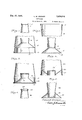
Figure 1 is a vertical longitudinal sectional view of a container constructed in accordance with the invention, the same being broken away for a distance of its length.
Fig. 2 is a view similar to Figure 1 showing the container converted for drinking purposes and supported in a holder when at rest.
Figure 3 is a view similar to Figure 1 showing a slight modification.
Figure 4 is a view similar to Figure 3 showing a further modification.
Figure 5 is a view similar to Figure 4 showing the container! inverted and supported in the holder therefor.
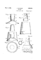
Figure 6 is a fragmentary vertical sectional view of a further modification.
Figure 7 is a view similar to Figure 5 showing another modification.
Figure 8 is a view similar to Figure 1 showing a still further modification.
Figure 9 is a bottom plan view.
Figure 10 is a side elevation partly in section of a further modified form of container.
Figure 11 is a sectional view on the line I l--| I of Figure 10.
Figure 12 is a fragmentary side elevation of a still further modification of container.
Similar reference characters indicate corresponding parts throughout the several views in the drawings.
Referring to the drawings in detail, particularly Figures 1 and 2, the container therein shown comprises a conical-shaped body l0, preferably made from sheet metal, and at the smaller end of this body is a removable top II which is 10 in the nature of a cap having an interlocking seam edge l2 with the body, while at the other or wider end of the said body is an inset bottom l3 having the interlocked seam edge 14 with said body. Interiorly of the body l0 and super- 15 imposed upon the bottom I3 is a holder having the flared or upwardly tapered base portion l5 and the rim I6.
The holder is removed from the body l0 by severing the bottom l3 in a circular path concentric to the portion I5 of the holder, it being understood, of course, that the said body I0 is inverted from the position shown in Figure 1 to avoid the loss of its contents and thereafter the holder is placed upon a support and the smaller end of the body In is telescoped into the rim N5 of said holder, whereby the container will be supported in a position for drinking purposes.
In Figure 3 of the drawings the bottom IT has the inner and outer annular flanged walls I 8 and I9, respectively, these being spaced apart to provide a clearance therebetween, so that the said bottom I1 may be cut at the fold 20 therein to release the holder 2| for functioning alike to the holder before described.
In Figure 4 of the drawings there is shown a further modification wherein the bottom 22 constitutes a holder when severed from the body 23 following the fold 24 in said bottom and such holder, centrally thereof, is formed with a cupshaped socket 25 for accommodating the smaller end of the body 23 of the container when inverted to this position.
The holder is also inverted to accommodate the smaller end of the body 23, as is shown in Figure 5 of the drawings.
In Figure 6 of the drawings there is shown a further modification, wherein the smaller end 26 of the body has the top 21 interlocked with the body by a rolled interlocking edge 28.
In Figure '7 of the drawings there is shown a further modification, wherein the holder 29 is a separate and independent unit from the body 30 of the container and the smaller end 3| of this body is telescoped into the socketed portion 55 32 of said holder 29, it being understood, of course, that the bottom at the wider end of the body 3| of the container is removed, so that the container may be utilized for drinking purposes.
In Figure 8 of the drawings there is shown a still further modification, wherein the holder 33 constitutes the bottom for the body 34 of the container and this holder has the socketed extension 35 for accommodating the smaller closure end 36 of the body 34 on separating the said holder 33 from the body 34.
In Figures 10 and 11 of the drawings there is shown a further modification, wherein the top 31 has formed therewith a releasing key 38 for easy detachment of the top 31 from the body 39 of the container.
In Figure 12 of the drawings there is shown a still further modification, wherein the body 40 of the container has the contracted or reduced neck 4|.
It shoulde be apparent that the container, under the various forms of construction, can be utilized for dispensing liquids and also as a drinking receptacle and when used as a drinking receptacle can be held in a holder when at rest, the holder either being a part of or independent from the said container.
What is claimed is:
A container of the character described comprising a bottle-like body, closure members lock seamed with opposite ends of said body, one of said closure members constituting a supporting base on separation thereof from the body, and a cup formed with the closure member constituting the base for telescopically receiving an end of the body when the latter has been separated from the closure member constituting said base for the holding of the said body in a perpendicular upstanding position when in the cup.
LOUIS W. CRAMER.
Priority Applications (1)
| Application Number | Priority Date | Filing Date | Title |
|---|---|---|---|
| US735028A US2024910A (en) | 1934-07-13 | 1934-07-13 | Container |
Applications Claiming Priority (1)
| Application Number | Priority Date | Filing Date | Title |
|---|---|---|---|
| US735028A US2024910A (en) | 1934-07-13 | 1934-07-13 | Container |
Publications (1)
| Publication Number | Publication Date |
|---|---|
| US2024910A true US2024910A (en) | 1935-12-17 |
Family
ID=24954051
Family Applications (1)
| Application Number | Title | Priority Date | Filing Date |
|---|---|---|---|
| US735028A Expired - Lifetime US2024910A (en) | 1934-07-13 | 1934-07-13 | Container |
Country Status (1)
| Country | Link |
|---|---|
| US (1) | US2024910A (en) |
Cited By (3)
| Publication number | Priority date | Publication date | Assignee | Title |
|---|---|---|---|---|
| US3371819A (en) * | 1965-10-23 | 1968-03-05 | Floroware Corp | Pot constructions |
| US5992662A (en) * | 1996-07-24 | 1999-11-30 | Dakota Enterprises, Llc | Container stand adapter |
| US20040134919A1 (en) * | 2003-01-10 | 2004-07-15 | Irwin Lynn B. | Multi-piece vessel |
-
1934
- 1934-07-13 US US735028A patent/US2024910A/en not_active Expired - Lifetime
Cited By (3)
| Publication number | Priority date | Publication date | Assignee | Title |
|---|---|---|---|---|
| US3371819A (en) * | 1965-10-23 | 1968-03-05 | Floroware Corp | Pot constructions |
| US5992662A (en) * | 1996-07-24 | 1999-11-30 | Dakota Enterprises, Llc | Container stand adapter |
| US20040134919A1 (en) * | 2003-01-10 | 2004-07-15 | Irwin Lynn B. | Multi-piece vessel |
Similar Documents
| Publication | Publication Date | Title |
|---|---|---|
| US2075721A (en) | Can drinking rim | |
| US2090320A (en) | Cocktail shaker | |
| US3091361A (en) | Containers | |
| US2122628A (en) | Container holder | |
| US3776458A (en) | Telescopic drinking straw | |
| US2077027A (en) | Container | |
| US1866805A (en) | Cup holder | |
| US2078149A (en) | Cap for toothpaste tubes | |
| US2838202A (en) | Combined cup, stand and handle for beverage cans | |
| US2322843A (en) | Combination container and cap remover | |
| US2728516A (en) | Closure cap and cup holder | |
| US2837234A (en) | Self contained drinking tube and bottle cap | |
| US2007449A (en) | Sealed fluid dispenser | |
| US2330878A (en) | Container | |
| US1679621A (en) | Container | |
| US2024910A (en) | Container | |
| US2330840A (en) | Container | |
| US2222290A (en) | Liquid container | |
| US2203911A (en) | Sanitary can cover | |
| US2333090A (en) | Paper cup | |
| US2070367A (en) | Detachable handle for receptacles | |
| US2052728A (en) | Receptacle for liquids | |
| US20160015198A1 (en) | Can type container changeable to type of cup or glass | |
| US2327010A (en) | Drinking attachment for beverage cans | |
| US1988044A (en) | Ice cream container attachment |