US2024902A - Radio receiving apparatus - Google Patents
Radio receiving apparatus Download PDFInfo
- Publication number
- US2024902A US2024902A US669717A US66971733A US2024902A US 2024902 A US2024902 A US 2024902A US 669717 A US669717 A US 669717A US 66971733 A US66971733 A US 66971733A US 2024902 A US2024902 A US 2024902A
- Authority
- US
- United States
- Prior art keywords
- circuits
- frequency
- tuning
- receiver
- radio
- Prior art date
- Legal status (The legal status is an assumption and is not a legal conclusion. Google has not performed a legal analysis and makes no representation as to the accuracy of the status listed.)
- Expired - Lifetime
Links
Images
Classifications
-
- H—ELECTRICITY
- H04—ELECTRIC COMMUNICATION TECHNIQUE
- H04B—TRANSMISSION
- H04B1/00—Details of transmission systems, not covered by a single one of groups H04B3/00 - H04B13/00; Details of transmission systems not characterised by the medium used for transmission
- H04B1/06—Receivers
- H04B1/16—Circuits
- H04B1/18—Input circuits, e.g. for coupling to an antenna or a transmission line
Definitions
- the present invention relates broadly to the reception of customary program signal-trains via modulated broadcast carrier waves, and more particularly to a means and method of clarication of the transmitted signals from a considerable fraction of the "static", and of loud signals in next adjacent broadcast Channels, as well 'as a considerable part of the man-made" static from operation of commutator-type motors, switches, telephone-dial Contacts, and similar mechanisms, now so tremendously annoying to the radio listener, and so destructive of real musical programs.
- An important object of my invention is to provide means, and a method of operation thereof, whereby the general clarity of the incoming broadcast signals is very greatly improved over customary present practice, as referred to just above.
- Another object is to provide means for tuning the noise-draining circuits concomitantly with the tuning of the usual dial, and without added manipulatory knobs.
- Another object is to provide noise-draining side circuits which shall at all times be set or tuned for especial acceptability of the non-desired signals, which are extraneous to those signals on the tuned-in broadcast being sought by listener.
- a further object is to very materially improve the selectivity of the receiver.
- An added object of value is to provide a radiofrequency receiver which in effect maintains a sharply cleared channel for the broadcast band tuned in and being received.
- Figure 1 shows a connection diagram of one form of my invention, attached to a radio-frequency receiver of typical, Wellknown type. Detector and subsequent stages are omitted, as well known.
- an apparatus including a radio-frequency antenna I, with the usual down lead 2, but connected at 3 with my invention proper consisting of twin drain circuits, the one on the left comprising the very large capacty 10 1 variable condenser 4, preferably of from to times the capacity of the usual radio-frequency tuning condensers in the main part of the receiver set, as will be enumerated later, but
- the small air inductance coil 5 of about A, to 1 6 the inductance of the coils in main tuning circuits oi' radio-frequency stages of the associated receiver, as will be referred to later.
- condenser 4 and inductance 5 will be so chosen, however, as to give a free oscillation frequency 'm this branch circuit, of approximately 10 kilocycles less than that of the main radio frequency stages 01' the set, and the outer end of 5 will be connected to ground at 6.
- a ⁇ similarly disposed side-drain circuit composed of the similarly "ganged” large condenser 'I of variable type, in series with another very small inductance coil 8, and likewise connected to ground at 9.
- the condenser and coil elements are here so chosen, however, as to give a free oscillation frequency about 10 kilocycles above that of the main radio-frequency tuned stages of the receiver set, for each position of the tuning dial.
- said coils can then be permanently connected to ground, as indicated, and. the factory amplifiers withdrawn.
- 4 and 1 may each be paralleled by small vernier type variable condensers, so set as to be readily manipulated by radio operator, to aid in the subsequent precision tuning of these drain circuits. But since such devices are well known expedients. I have not shown the same, in order to not complicate the drawing. Since the side-drain circuits add materially to clarity of reception, but at the same time may slightly reducegthe "distant" signals, I preferably arrange contact 3 in the form of a jack, so that it can be opened-up if desired, when "distance" is being sought for by the listener-in.
- connection between my invention proper and the rest of the customary'receiver set is shown by the antenna line 21, leading to antenna input variable condenser o, which is ganged by connecting means 4a with succeeding radio-frequency variable condensers to be spoken of later,
- the condensers 4, 1, and I 0 may preferably be placed on the ground side of their respective coils, to simpliiy the interconnectlng or ganging means, and lessen insulation requirements thereon.
- the many turn secondary I4, of transformer !2 may be bridged by the second stage tuning condenser !5, which is grounded on lower side at 5a, ⁇ the upper end of said bridge circuit being -carried through C-battery C to grid IB of first amplifier tube H, the battery polarities being as indicated, although more than one cell may in some cases be required.
- One filament lead into this tube is shown at !8, which connects to' said ground connection I 59. through the filament battery 18. so as to form the necessary grid-return lead, the other filament lead being grounded, or connected to a common return lead at l9.
- the plate 20 of this tube goes to and thru primary 2! of second radio-fraquency transformer 22, on to positive oi' the many cell B-battery 23, and to ground 24, while transformer secondary 25 of many turns is bridged in turn by the next ganged variable condenser 26, tuning its associated transformer to the desired signal frequency, the lower side of this condenser 'being 'grounded at 26a, and the upper plate oi said condenser being carried thru C-battery C2 i denser 25, and to the ground connection 26a, .so as to form the necessary and customary grid-return lead, and second filament lead 33 to ground, with plate sl in turn connected to the fewturn primary coil 32 of final radio-frequency transformer 33, and thence through the multicell B-battery 34, or its power-pack equivalent, to ground or common-return line 35, while the many-turn secondary 36 of said transformer may be connected through its leads 31 and 38, either to an additional radio-frequency ampliiying tube stage, with associated tuning conden
- a heavy metal ball is shown at 51, a light cork ball at 52, these being carried by the appropriate light piano wires 53 and 54 respectively, attached at 55 and 56 so as to depend from, but be very freely oscillable around, the stiiT supportingmeans 51, of any desired material.
- the side-drain condensers are each made of several times the electrical Capacity of the tuning condenser in main antenna input circuit of the receiver proper, Whereas the inductance coil in series with each such side-drain condenser is made proportionately less in inductance than the coil in the antenna input tuning circuit of said receiver, but all are proportioned so as to give the Iree oscillation frequency conditions above enumerated.
- the latter co-rresponds to the electrical conditions purpcsely set up in one of the sidedrain-circuits such as 3-4-5--6, for example, of Figure 1, in which current flow corresponds to velocity of swing or motion in the mechanical analogue.
- the 5 side-drain circuits can be separated temporarily from the aerial 2, in Figure 1, by Operating the jack at junction point 3, so as to clear the 2-21 line from that extending from 6 to 9.
- a radio-frequency broadcast receiver In the input end of a radio-frequency broadcast receiver, three series resonance type tuned circuits each containing one inductance and one capacity element only, said circuits all being conductively connected in parallel with each other, a receiving antenna also connected to this parallelling connection and to nothing else in said receiver, the inductance on one of .said circuits only being inductively coupled to the input side of a radio-frequency amplifier, this one of said circuits being tunable to an intermediate frequency with respect to the other two, with a constantly maintainable spaeing of 10 kilocycles respectively therebetween, to each of the said other two, a common tuning-means mechanically connected to the tuning elements of all said circuits and adapted to produce the' ⁇ ceiving antenna conductively connected to the paralleling connection of said circuits and to no other elements of said receiver, a mechanical connection means between the tuning elements of said three circuits and arranged to provide a constantly maintained spaced tuning successively 10 kilo-cycles apart between the respective circuits, throughout the
- An input circuit for a radio receiver operable on modulated carrier waves comprising an antenna connected conductively to three series resonant circuits only, all being paralleled at the antema connection thereto, each of said circuits comprising a single inductance element and a single Capacity element in series, with a much lower inductance and a much higher Capacity in two of said circuits than in the other, which latter only is provided with a signal transmitting means to a radio-frequency amplifier device coupled thereto, all three circuits containing variable tuning means mechanically interconnected therebetween, said latter means providing a 10 kilocycle maintained frequency spacing between each of 'the low inductance circuits and the one of higher inductance, which latter is maintainable at a frequency therebetween, throughout the usual broadcast range of reception.
- a receiver operable on broadcast modulated radio-frequency carrier waves comprising a multi-stage multi-tuned radio-frequency amplifying means, three concomitantly tunable series resonant circuits conduci tively connected in parallel with each other, each comprising one inductance coil and one condenser only, a mechanically interconnected common tuning means applied to the tunable elements of all said circuits and of said amplifying means, one of said circuits being maintainable at an intermediate frequency with respect to the other two, and identical with that of said amplifying means, 5 with a kilo-cycle maintained spacing between said one circuit and each of the other two said circuits, throughout the usual broadcast range, said one circuit containing a much higher inductance and a much lower Capacity than either 10 of the other two in parallel therewith, and being characterized as the only circuit of the three provided with signal transmitting coupling with the said amplifying means.
- a receiver operable on broadcast modulated radio-frequency carrier waves comprising a multi-stage multi-tuned radio-frequency amplifying means, two concomitantly tunable side branch circuits only, conductively connected in parallel with each other, a concomitantly tunable input circuit for said amplifying means also connected in parallel with said side circuits, a mechanically connected common tuning means applied to the tuning elements of all said circuits, and providing a substantally 10 kilo-cycle maintained spacing between said input circuit and each of the two said side circuits, With the former lying therebetween, for all settings within the usual broadcast' range of frequencies, each of said circuits containing one coni denser and one inductance coil only, in series, said side circuits each containing a relatively large condenser and a relatively small inductance, With respect to the corresponding parts in the said input circuit, and an antenna connected to the common connection point of all said circuits only.
- a radio broadcast receiver comprising a multi-stage multi-tuned radiofrequency amplifying-means, a series resonant tunable input circuit coupled therewith, a branch series resonant tunable circuit connected in par*- allel with said input circuit, said branch circuit containinga very large capacity element and a very small inductance element compared with similar elements provided in said input circuit, a mecham'cal coupling means connecting the tuning elements of both of said ⁇ circuits and providing a maintained 10 kilo-cycle frequency spacing therebetween throughout the usual broadcast range, said mechanical coupling also Operating the tuning elements of said amplifying means and maintaining therein the same frequency as that in said input circuit at any given instant, and an aerial connected only to the common connection point of said series resonant circuits.
- a radio broadcast receiver arranged as in claim 6, in which a disconnecting jack is provided at the parallel connection of the two series resonant tunable circuits mentioned, so that the said branch circuit can be disconnected when desired. 6
Landscapes
- Engineering & Computer Science (AREA)
- Computer Networks & Wireless Communication (AREA)
- Signal Processing (AREA)
- Input Circuits Of Receivers And Coupling Of Receivers And Audio Equipment (AREA)
Description
-Dec 17, 1935. J A JR V 2,04,902
I RADIO RECEIVINGAPPABATUS Filed May 6, 1953 lllll//////// 55 67 56 5&
. Hag, INVENTOR.
Patented Dec. 17, 1935 UNITED STATES PATENT OFFICE RADIO RECEIVING APPARATUS James L. Adams, Jr., Youngstown, Ohio y Application May 6, 1933, Serial No. 669,'717 7 Claims. (Cl. 250-750) The present invention relates broadly to the reception of customary program signal-trains via modulated broadcast carrier waves, and more particularly to a means and method of clarication of the transmitted signals from a considerable fraction of the "static", and of loud signals in next adjacent broadcast Channels, as well 'as a considerable part of the man-made" static from operation of commutator-type motors, switches, telephone-dial Contacts, and similar mechanisms, now so tremendously annoying to the radio listener, and so destructive of real musical programs.
An important object of my invention is to provide means, and a method of operation thereof, whereby the general clarity of the incoming broadcast signals is very greatly improved over customary present practice, as referred to just above.
Another object is to provide means for tuning the noise-draining circuits concomitantly with the tuning of the usual dial, and without added manipulatory knobs.
Another object is to provide noise-draining side circuits which shall at all times be set or tuned for especial acceptability of the non-desired signals, which are extraneous to those signals on the tuned-in broadcast being sought by listener.
A further object is to very materially improve the selectivity of the receiver.
An added object of value is to provide a radiofrequency receiver which in effect maintains a sharply cleared channel for the broadcast band tuned in and being received.
Other objects of importance will be self-evident to anyone skilled in the art to which my invention appertains.
With all the above and other objects in mind V I have provided a method' and apparatus for attaining substantially all the, results enumerated, in a convenient way. A
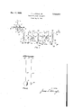
In the drawing, Figure 1 shows a connection diagram of one form of my invention, attached to a radio-frequency receiver of typical, Wellknown type. Detector and subsequent stages are omitted, as well known.
In Figure 2, I have shown in elevation, a simple mechanical analogue illustrative of the electrical principle involved in my invention.
In all the figures, identical parts are designated by the same part numbers.
The drawing is shown for purposes of illustration only, and not as determining the limits of my inventions, or of its possible applications,
and show a type of apparatus which is readily adapted to, and may be conveniently built in with any customary type of standard broadcast receiver, without great alteration thereto.
In accordanc with the present invention,`and referring now more particularly to Figure 1, there may be provided an apparatus including a radio-frequency antenna I, with the usual down lead 2, but connected at 3 with my invention proper consisting of twin drain circuits, the one on the left comprising the very large capacty 10 1 variable condenser 4, preferably of from to times the capacity of the usual radio-frequency tuning condensers in the main part of the receiver set, as will be enumerated later, but
adapted to be tuned concomitantly therewith bY V mounting on a common shaft, or otherwise ganging together", as by the common mechanical connecting means da, and as well known in the art.
In series with condenser 4 is placed the small air inductance coil 5, of about A, to 1 6 the inductance of the coils in main tuning circuits oi' radio-frequency stages of the associated receiver, as will be referred to later.
condenser 4 and inductance 5 will be so chosen, however, as to give a free oscillation frequency 'm this branch circuit, of approximately 10 kilocycles less than that of the main radio frequency stages 01' the set, and the outer end of 5 will be connected to ground at 6.
On the opposite side of 2 and 3 is shown a `similarly disposed side-drain circuit composed of the similarly "ganged" large condenser 'I of variable type, in series with another very small inductance coil 8, and likewise connected to ground at 9.
The condenser and coil elements are here so chosen, however, as to give a free oscillation frequency about 10 kilocycles above that of the main radio-frequency tuned stages of the receiver set, for each position of the tuning dial.
Thus the side circu'ts including 4 and 'I will follow the tuning of the main receiver tuning condenser circuits, as the dial is turned and connecting means 4a manipulated, but always 10 kilocycles away therefrom, on opposite sides ot the normal tuned position, of receiver proper.
such settings of the draining circuit condensers can be determined readily during the course of manufactu'ing the main receiver set, by temporarily connecting coils 5 and 8 thru factory amplifier and detector sets to earphones used just for such tuning purposes, instead of direct to ground, as shown.
After completion of the factory tuning, said coils can then be permanently connected to ground, as indicated, and. the factory amplifiers withdrawn.
If desired, however, 4 and 1 may each be paralleled by small vernier type variable condensers, so set as to be readily manipulated by radio operator, to aid in the subsequent precision tuning of these drain circuits. But since such devices are well known expedients. I have not shown the same, in order to not complicate the drawing. Since the side-drain circuits add materially to clarity of reception, but at the same time may slightly reducegthe "distant" signals, I preferably arrange contact 3 in the form of a jack, so that it can be opened-up if desired, when "distance" is being sought for by the listener-in.
The connection between my invention proper and the rest of the customary'receiver set, is shown by the antenna line 21, leading to antenna input variable condenser o, which is ganged by connecting means 4a with succeeding radio-frequency variable condensers to be spoken of later,
and is connected through primary ll of radiofrequency transforner !2, to ground, or to chassis-frame I3. In some cases the condensers 4, 1, and I 0 may preferably be placed on the ground side of their respective coils, to simpliiy the interconnectlng or ganging means, and lessen insulation requirements thereon. As a typical, but not necessarily exclusive type of connection to be used in such standard or usual receiver set, the many turn secondary I4, of transformer !2, may be bridged by the second stage tuning condenser !5, which is grounded on lower side at 5a,` the upper end of said bridge circuit being -carried through C-battery C to grid IB of first amplifier tube H, the battery polarities being as indicated, although more than one cell may in some cases be required. i
One filament lead into this tube is shown at !8, which connects to' said ground connection I 59. through the filament battery 18. so as to form the necessary grid-return lead, the other filament lead being grounded, or connected to a common return lead at l9. i
The plate 20 of this tube goes to and thru primary 2! of second radio-fraquency transformer 22, on to positive oi' the many cell B-battery 23, and to ground 24, while transformer secondary 25 of many turns is bridged in turn by the next ganged variable condenser 26, tuning its associated transformer to the desired signal frequency, the lower side of this condenser 'being 'grounded at 26a, and the upper plate oi said condenser being carried thru C-battery C2 i denser 25, and to the ground connection 26a, .so as to form the necessary and customary grid-return lead, and second filament lead 33 to ground, with plate sl in turn connected to the fewturn primary coil 32 of final radio-frequency transformer 33, and thence through the multicell B-battery 34, or its power-pack equivalent, to ground or common-return line 35, while the many-turn secondary 36 of said transformer may be connected through its leads 31 and 38, either to an additional radio-frequency ampliiying tube stage, with associated tuning condensers, ground connections, etc., as before, or directly to the customary detector, either tube or crystal type, and from thence through the usual audio ainpiiiying stage or stages to the final outlet to loud-speaker, or possibly ear-phones, all as per well-known methods and connections, necessitating no further comment here, particularly as such final amplifying elements and connections are in no wise incorporated in my claims.
In Figure 2, a heavy metal ball is shown at 51, a light cork ball at 52, these being carried by the appropriate light piano wires 53 and 54 respectively, attached at 55 and 56 so as to depend from, but be very freely oscillable around, the stiiT supportingmeans 51, of any desired material.
Reverting now to Figure 1, it will be observed that I have provided side drain circuits which are especially receptive to all incoming signals which lie in the two broadcast channels next to that for which the broadcast receiver proper is tuned, one of these side-drain circuits lying 10 kilocycles above, and the other 10 kilocycles below that of the desired receiver signal.
Not only are these side-drain circuits adapted to tune to their respective irequencies, always just 10 kilocycles each way from the main signal requency, as the main condenser tuning knob is rotated, but these side-drain circuits are made still further receptive to the non-desired signals by a proper selection of the electri'cal constants pertaining to these paths. Thus the side-drain condensers are each made of several times the electrical Capacity of the tuning condenser in main antenna input circuit of the receiver proper, Whereas the inductance coil in series with each such side-drain condenser is made proportionately less in inductance than the coil in the antenna input tuning circuit of said receiver, but all are proportioned so as to give the Iree oscillation frequency conditions above enumerated.
Now it is Vastly easier for a signal of a given radio frequency to build up a response current in a tuned circuit which contains a Very low inductance, so that it will be much easier !crunwanted signals occupying the adjacent broadcast channels to get in and through the respective side-drain circuits, than for these same interfering signals to try and force their way through the much higher inductance path connected with the main antenna tuning circuit on input side of the receiver proper, particularly as this latter circuit will be 10 kilocycles away in frequency setting, at all times.
Thus selectivity of the receiver proper will be greatly improved, and at the same time the desired incoming signals will be materially clarified, because the diverted side-drain Signals do not pass through a loud-speaker, andso are inaudible.
It is also evident that extraneous impuises of steep wave-front, such as the static from lightning discharges, will, upon encountering the antenna l, and following down the lead-in 2, encounter at 3 a divided circuit of three branches, the two side-drain paths of which through 4-- 5-6 and 1--8-9 will be far more receptive to such impulses than is the main receiver antenna input through 2-lo--ll-l3.
Thus only to of the original nowdesired impulse striking l will be able to penetrate through the coil ll, by far the most of it being diverted through the side circuits above mentioned, which do not contain a loud-speaker, so that the signal actually amplified by the receiver proper from H-l2-I4 on will be greatly cleared up of the undesired impulse effects, whether from adjacent channel program waves, lightning, or from a variety of circuit-switching Operations of the nuisance" types, such as those 'li I electrical of vacuum-cleaners, telephone-dialing contacts, etc.
Since parts I l to 38 inclusive, pertain to a usual type of broadcast receiver, the connectio-ns of which are well known, and which enter in no way into my invention proper, or into the claims, I believe that further description thereof may well be omitted, in the interest of brevity.
Referring now to Figure 2, I have arranged a mechanical analogue, in which the high-inertia element takes the place of the highly inductive coil H of Figure 1, while the light ball 52 typifies the coil 5 of very low inductance of one of the side-drain circuits in this figure.
In a pendulum, the "spring return effect, or tendency to come back to mid-position, is supplied in this case by gravity, and is therefore in exact proportion to the respective weights involved, 5! oscillating as though a strong spring were doing the returning to zero, whereas 52 will operate as though a relatively Weak spring were unctioning here. And since this spring-return efiect really is in exact .proportion to the respective weights, we find that both pendulums, if of the same effective length, Swing in precise unison, the time period of oscillation being the same in each case; in other words, both systems have identical tuning. But if both balls are standing still, and a light feather which is oscillating back and forth under power, and continuously, at a pace slightly faster or slower than the normal "free" frequency of the ball systems, is brought up into contact with one of the wires 53 or 54, it will be found that 51-53 is difiicult to get into oscillation at this "off" frequency, whereas the 52-54 system is vastly easier to get speeded up.
Now the latter co-rresponds to the electrical conditions purpcsely set up in one of the sidedrain-circuits such as 3-4-5--6, for example, of Figure 1, in which current flow corresponds to velocity of swing or motion in the mechanical analogue.
In such mechanical analogues it must also always be remembered that a weak sp-ring corresponds to a condenser of large capacity, while a strong spring is typified by a very small condenser, which is "electrically Stifler or more resistant to current flow, than a big condenser, under equivalent frequency and Voltage conditions.
Again referring to Figure 2, it will be self-evident that a sudden impulse striking 53 and 54 concomitantly, will be able to induce. a vastly greater Swing in the 52-54 system than in the more massive 5l--53 combination.
Now in mechanical analogues of electrical circuits, it is, as before mentioned, necessary to keep clearly in mind that Velocity-of-motion corresponds with current-flow, and that, conversely, conditions corresponding with the 52-54 system wi1l,'therefore, be the better suited for induction of large values of current therein.
This is precisely what I have done in each of the side-drain circuits 3--4-5-5, and S--l-B-Q, of Figure 1, for example, where the tra-large condensers and Very small inductances permit tuning to the required off frequencies, but at the same time for circuits which are especially receptive to the signals which it is desired to eliminate.
These side circuits will of course take in some of the strength of the signal of the desired incoming program, but ordnarily every receiver has a reserve of possible amplification available, the amount normally used being limited because of the usual noise background". If I eliminate a large fraction of the latter, more amplification can be utilized to bring up the Volume to required Value.
In searching for extreme distance signals, the 5 side-drain circuits can be separated temporarily from the aerial 2, in Figure 1, by Operating the jack at junction point 3, so as to clear the 2-21 line from that extending from 6 to 9.
I believe that the mechanical analogue brings 10 out the desired functioning of the electrical sidedrain circuits clearly enough to make unnecessary anymore elaborate description thereof than has already been given. In Figure 1, it will be self-evident to anyone skilled in the art to which my invention appertains, that the ganged condensers 4, 1, and ne, with their respective coils, must form systems of the straight-line-frequency type, as a preferred Construction, so that the respective 4, 2, and 7 tunings will remain approximately 10 kilocycles apart, in the order given, throughout the entire broadcast range of reception, and not for just some fractional element thereof.
In the use of the method and apparatus of my invention, certain very definite advantages accrue from the sub-division of non-desired incoming signals among a multiplicity of circuits, the majority of which are made very especially receptive to such signals, but have no loudspeaker-connections, so that in effect these nondesired signals are removed from the field, thus very materially improving the clarity and quality of the remanent signals which enter the broadcast receiver proper, and eventually emerge from the loud-speaker.
Other important ,advantages accrue from the use of high-capacity, low-inductance elements in the side drain circuits, as Compared with the corresponding units or elements in the broadcast receiver proper.
Still other advantages accrue from the spaced tuning maintained between the broadcast receiver input circuit, and the two side-drain circuits, respectively, for all positions of the main tuning djal, as heretofore outlined, but all tuned from this common dial.
While I have shown and described preerred forms of my invention, many modifications may be made both in its structure, and in the mode of operation, without departing from the spirit of said invention, or the scope of my broader claims. Thus, in some cases, it may be found that sufficient clarification of incoming signals can be obtained by the use of but a single one of the two side-drain circuits which I have preferred to illustrate and describe in the present application as probably the better construction for the purpose intended.
What I claim is:
1. In the input end of a radio-frequency broadcast receiver, three series resonance type tuned circuits each containing one inductance and one capacity element only, said circuits all being conductively connected in parallel with each other, a receiving antenna also connected to this parallelling connection and to nothing else in said receiver, the inductance on one of .said circuits only being inductively coupled to the input side of a radio-frequency amplifier, this one of said circuits being tunable to an intermediate frequency with respect to the other two, with a constantly maintainable spaeing of 10 kilocycles respectively therebetween, to each of the said other two, a common tuning-means mechanically connected to the tuning elements of all said circuits and adapted to produce the' `ceiving antenna conductively connected to the paralleling connection of said circuits and to no other elements of said receiver, a mechanical connection means between the tuning elements of said three circuits and arranged to provide a constantly maintained spaced tuning successively 10 kilo-cycles apart between the respective circuits, throughout the customary broadcast range of frequencies, the intermediate frequency circuit only containing a means of transmitting signals to the input circuit of said radio-frequency receiver, said intermediate frequency circuit also containing a lower capacity and a higher inductance than either of the two remaining circuits of the three first mentioned, and all three of these three cir- :cuits being connected at remaining end to ground,
the whole constituting a means for eliminating interference with a desired broadcast channel by those immediately adjacent thereto on each side of the selected frequency.
3. An input circuit for a radio receiver operable on modulated carrier waves, comprising an antenna connected conductively to three series resonant circuits only, all being paralleled at the antema connection thereto, each of said circuits comprising a single inductance element and a single Capacity element in series, with a much lower inductance and a much higher Capacity in two of said circuits than in the other, which latter only is provided with a signal transmitting means to a radio-frequency amplifier device coupled thereto, all three circuits containing variable tuning means mechanically interconnected therebetween, said latter means providing a 10 kilocycle maintained frequency spacing between each of 'the low inductance circuits and the one of higher inductance, which latter is maintainable at a frequency therebetween, throughout the usual broadcast range of reception.
4. In a receiver operable on broadcast modulated radio-frequency carrier waves, the combinaticn comprising a multi-stage multi-tuned radio-frequency amplifying means, three concomitantly tunable series resonant circuits conduci tively connected in parallel with each other, each comprising one inductance coil and one condenser only, a mechanically interconnected common tuning means applied to the tunable elements of all said circuits and of said amplifying means, one of said circuits being maintainable at an intermediate frequency with respect to the other two, and identical with that of said amplifying means, 5 with a kilo-cycle maintained spacing between said one circuit and each of the other two said circuits, throughout the usual broadcast range, said one circuit containing a much higher inductance and a much lower Capacity than either 10 of the other two in parallel therewith, and being characterized as the only circuit of the three provided with signal transmitting coupling with the said amplifying means.
5. In a receiver operable on broadcast modulated radio-frequency carrier waves, the combination comprising a multi-stage multi-tuned radio-frequency amplifying means, two concomitantly tunable side branch circuits only, conductively connected in parallel with each other, a concomitantly tunable input circuit for said amplifying means also connected in parallel with said side circuits, a mechanically connected common tuning means applied to the tuning elements of all said circuits, and providing a substantally 10 kilo-cycle maintained spacing between said input circuit and each of the two said side circuits, With the former lying therebetween, for all settings within the usual broadcast' range of frequencies, each of said circuits containing one coni denser and one inductance coil only, in series, said side circuits each containing a relatively large condenser and a relatively small inductance, With respect to the corresponding parts in the said input circuit, and an antenna connected to the common connection point of all said circuits only.
6. In a radio broadcast receiver, the combination comprising a multi-stage multi-tuned radiofrequency amplifying-means, a series resonant tunable input circuit coupled therewith, a branch series resonant tunable circuit connected in par*- allel with said input circuit, said branch circuit containinga very large capacity element and a very small inductance element compared with similar elements provided in said input circuit, a mecham'cal coupling means connecting the tuning elements of both of said` circuits and providing a maintained 10 kilo-cycle frequency spacing therebetween throughout the usual broadcast range, said mechanical coupling also Operating the tuning elements of said amplifying means and maintaining therein the same frequency as that in said input circuit at any given instant, and an aerial connected only to the common connection point of said series resonant circuits.
7. A radio broadcast receiver arranged as in claim 6, in which a disconnecting jack is provided at the parallel connection of the two series resonant tunable circuits mentioned, so that the said branch circuit can be disconnected when desired. 6
JAMES L. ADAMS, JR.
Priority Applications (1)
| Application Number | Priority Date | Filing Date | Title |
|---|---|---|---|
| US669717A US2024902A (en) | 1933-05-06 | 1933-05-06 | Radio receiving apparatus |
Applications Claiming Priority (1)
| Application Number | Priority Date | Filing Date | Title |
|---|---|---|---|
| US669717A US2024902A (en) | 1933-05-06 | 1933-05-06 | Radio receiving apparatus |
Publications (1)
| Publication Number | Publication Date |
|---|---|
| US2024902A true US2024902A (en) | 1935-12-17 |
Family
ID=24687436
Family Applications (1)
| Application Number | Title | Priority Date | Filing Date |
|---|---|---|---|
| US669717A Expired - Lifetime US2024902A (en) | 1933-05-06 | 1933-05-06 | Radio receiving apparatus |
Country Status (1)
| Country | Link |
|---|---|
| US (1) | US2024902A (en) |
-
1933
- 1933-05-06 US US669717A patent/US2024902A/en not_active Expired - Lifetime
Similar Documents
| Publication | Publication Date | Title |
|---|---|---|
| US2141756A (en) | Multirange receiver | |
| US2443935A (en) | Superheterodyne radio receiver | |
| US2173898A (en) | Radio signal receiving system | |
| US2668235A (en) | Tuning system for wave-signal receivers | |
| US2024902A (en) | Radio receiving apparatus | |
| US2843683A (en) | Television tuner input circuit | |
| GB546248A (en) | Improvements in or relating to electric tuning systems | |
| US2390768A (en) | Variable selectivity amplifier | |
| US1937099A (en) | Radio receiving apparatus | |
| US2347315A (en) | Radio receiver | |
| US2222043A (en) | Selective wave transmission | |
| US2209982A (en) | Oscillator tuning system | |
| US2124211A (en) | Combined amplification and tuning controls | |
| US2646500A (en) | High-frequency tuner | |
| US1933778A (en) | Radio receiving system | |
| US2024816A (en) | Radio receiving system | |
| US2415810A (en) | Radio receiving system | |
| US2137475A (en) | Signal selector circuits | |
| US1944119A (en) | Convertible band pass receiver | |
| US2226488A (en) | Radio frequency rejector circuit | |
| US1895247A (en) | Method and means of extending frequency range of radio apparatus | |
| US2075501A (en) | Radio receiving system | |
| US1969209A (en) | Radio receiving apparatus | |
| US2285766A (en) | Image wave suppressor | |
| US2189304A (en) | Station selector |