US202425A - Improvement in nail-plate-feeding mechanisms - Google Patents
Improvement in nail-plate-feeding mechanisms Download PDFInfo
- Publication number
- US202425A US202425A US202425DA US202425A US 202425 A US202425 A US 202425A US 202425D A US202425D A US 202425DA US 202425 A US202425 A US 202425A
- Authority
- US
- United States
- Prior art keywords
- plate
- nail
- carriage
- improvement
- ratchet
- Prior art date
- Legal status (The legal status is an assumption and is not a legal conclusion. Google has not performed a legal analysis and makes no representation as to the accuracy of the status listed.)
- Expired - Lifetime
Links
- 230000007246 mechanism Effects 0.000 title description 2
- 238000013459 approach Methods 0.000 description 1
- 238000005452 bending Methods 0.000 description 1
Images

Classifications
-
- B—PERFORMING OPERATIONS; TRANSPORTING
- B21—MECHANICAL METAL-WORKING WITHOUT ESSENTIALLY REMOVING MATERIAL; PUNCHING METAL
- B21G—MAKING NEEDLES, PINS OR NAILS OF METAL
- B21G3/00—Making pins, nails, or the like
- B21G3/32—Feeding material to be worked to nail or pin making machines
Definitions
- Figure 1 represents in side elevation sutilcient of a nail-plate-feeding device to illustrate my invention
- Fig. 2 a top view thereof 5 Fig. 3, a section on the line 2 2 5 and Fig. 4 a section on the line 3 3.
- the bed a upon which rests the nail-plate b, is shaped preferably as shown in cross-section, Fig. 4, to receive and guide the carriage c, provided with the clamp d, shown, in this instance of my invention, as a pair of jaws, one of which is pivoted at e to the carriage.
- the jaws are closed upon the plate b by a nut, f, on a screw-stud, 4, connected with one and extended through the other jaw, and are opened by a spring, 5.
- Abearing, g, on the carriage holds a stud, h, upon which is placed a ratchet and pinion, z', having ratchet-teeth 6 and gear-teeth 7.
- the gear-teeth are engaged by the teeth of a rack, k, which, connected atl with some reciprocating or moving art of the punch, (not shown,) is reciprocated longitudinally after each operation of the punch.
- the ratchetteeth 6 are engaged by a pawl
- the holders p q, to keep the nail-plate down upon thebed a are, in this instance, made as arms projecting from shafts 8, at the lower ends of which are notched plates r, against which bear springs s.
- the .arms of both holders p q should extend over the plate, as shown by arm p, to keep the plate from bending upward from the bed when bcing pushed forward; but when the carriage approaches each arm the end of the clamp d first strikes the end of the arm, swinging it away from above the nailplate, and then the carriage pushes it farther away, into the position shown by holder q, leaving the carriage free to pass the holders one by one.
- the spring s is not sufficiently powerful to hold the shaft S and arm against the action of the jaw and carriage. After the carriage or clamp has presented the nail-plate to the punch quite up to the outer end of the plate, it is necessary to move the carriage backward to its original position, to again receive and feed forward another plate.
- the pawl m is drawn out by the hand-lever t until a latch, u, engages a notch in the pawl and holds it out of engagement with the ratchet-teeth 6, so that the carriage can be shoved backward by hand, the ratchet and pinion then turning freely.
- I claim- 1 In a nail-plate-feeding mechanism, a carriage, a clamp to hold the nail-plate, a ratchet and connected pinion, a pawl to engage the ratchet, a device to withdraw the pawl, and a reciprocating rack to rotate the pinion intermittingly, they being combined to operate substantially as described. Y
Landscapes
- Engineering & Computer Science (AREA)
- Mechanical Engineering (AREA)
- Portable Nailing Machines And Staplers (AREA)
Description
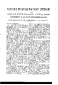
0. ELUS. Nail-Plate Feeding-Mechanism.
No. 202,425. Patented April 16, 1878.
C Pian- ILPETERS, PHOTO-LITHOGAPNER. WASHINGTON. D C
UNITED STATES PATENT OFFICE.
CHARLES ELLIS, OF BOSTON, MASS., ASSIGNOR TO GLOBE NAIL COMPANY.
IMPROVEMENT IN NAIL-PLATE-FEEDING MECHANISMS.
Specification forming'part of Letters Patent No. 202,425, dated April 16, 1878; application led January 11, 1878.
ally from twelve to twenty feet in length, and
somewhat wider than the length of the nails, there being at each edge of the plate a rib to form the heads of the nails. This long strip has to be fed automatically to the punches, be fed just so far at each step, and be kept down straight. In this invention the strip,
held at its rear end, is fed forward by an intert mittingly-operated carriage provided with a clamp, the former being actuated by a reciprocating rack or gear. Holding devices retain the plate down upon the bed, and during the forward movement of the carriage the holders turn from above the plate and permit the carriage and jaws to pass forward until the plate is cut up quite to the jaws.
Figure 1 represents in side elevation sutilcient of a nail-plate-feeding device to illustrate my invention; Fig. 2, a top view thereof 5 Fig. 3, a section on the line 2 2 5 and Fig. 4 a section on the line 3 3.
The bed a, upon which rests the nail-plate b, is shaped preferably as shown in cross-section, Fig. 4, to receive and guide the carriage c, provided with the clamp d, shown, in this instance of my invention, as a pair of jaws, one of which is pivoted at e to the carriage. The jaws are closed upon the plate b by a nut, f, on a screw-stud, 4, connected with one and extended through the other jaw, and are opened by a spring, 5.
Abearing, g, on the carriage holds a stud, h, upon which is placed a ratchet and pinion, z', having ratchet-teeth 6 and gear-teeth 7. The gear-teeth are engaged by the teeth of a rack, k, which, connected atl with some reciprocating or moving art of the punch, (not shown,) is reciprocated longitudinally after each operation of the punch.
The ratchetteeth 6 are engaged by a pawl,
m, pressed into engagement therewith by a spring, n. As the rack moves in the direction of the arrow, Fig. 1, the ratchet and pinion 'i move, in the direction of the arrow 7, about v the stud h,- but when the rack moves in the opposite direction the pawl m, then engaging and holding the ratchet and pinion i fast, the carriage and clamp are moved forward with the rack a distance determined by the size of the ratchet-teeth 6, the ratchet-pinion being changed from time to time, according to the size of the nail being cut.
The carriage will be provided with a suitable friction device to prevent its moving on the bed except when actuated positively by the rack.
The holders p q, to keep the nail-plate down upon thebed a, are, in this instance, made as arms projecting from shafts 8, at the lower ends of which are notched plates r, against which bear springs s. When the carriage and nailplate are in the position shown in Fig. 2, the .arms of both holders p q should extend over the plate, as shown by arm p, to keep the plate from bending upward from the bed when bcing pushed forward; but when the carriage approaches each arm the end of the clamp d first strikes the end of the arm, swinging it away from above the nailplate, and then the carriage pushes it farther away, into the position shown by holder q, leaving the carriage free to pass the holders one by one. The spring s is not sufficiently powerful to hold the shaft S and arm against the action of the jaw and carriage. After the carriage or clamp has presented the nail-plate to the punch quite up to the outer end of the plate, it is necessary to move the carriage backward to its original position, to again receive and feed forward another plate.
To do this the pawl m is drawn out by the hand-lever t until a latch, u, engages a notch in the pawl and holds it out of engagement with the ratchet-teeth 6, so that the carriage can be shoved backward by hand, the ratchet and pinion then turning freely.
In practice, the motion of the rack is automatically stopped just before the clamp reaches the punch, and the carriage is started by a lever back just far enough to insure that the punch shall not strike the clamp.
The short reciprocations of the rack move the carriage forward intermittingly. rIhe groove a2 in the bed receives and guides the clamp d, and permits the nail-plate to bear smoothly from end to end on the bed a.
I claim- 1. In a nail-plate-feeding mechanism, a carriage, a clamp to hold the nail-plate, a ratchet and connected pinion, a pawl to engage the ratchet, a device to withdraw the pawl, and a reciprocating rack to rotate the pinion intermittingly, they being combined to operate substantially as described. Y
2. The combination, with a carriage and clamp to move vthe nail-plate forward intermittingly, of holders to keep the nail-plate down upon. the bed, the holders being constructed to be automaticallbT turned aside from over the nail-plate for the passage of the carriage beyond them, substantially as and for the purpose described.
In testimony whereof I have signed my name to this specication in the presence of two subscribing witnesses.
CHARLES ELLIS.
Witnesses: -Y
GWV. GREGORY,
.W. J. PRATT.
Publications (1)
| Publication Number | Publication Date |
|---|---|
| US202425A true US202425A (en) | 1878-04-16 |
Family
ID=2271830
Family Applications (1)
| Application Number | Title | Priority Date | Filing Date |
|---|---|---|---|
| US202425D Expired - Lifetime US202425A (en) | Improvement in nail-plate-feeding mechanisms |
Country Status (1)
| Country | Link |
|---|---|
| US (1) | US202425A (en) |
-
0
- US US202425D patent/US202425A/en not_active Expired - Lifetime
Similar Documents
| Publication | Publication Date | Title |
|---|---|---|
| US202425A (en) | Improvement in nail-plate-feeding mechanisms | |
| US580556A (en) | Frank j | |
| US302900A (en) | fenerty | |
| US409830A (en) | Wire-stitching machine | |
| US659630A (en) | Wad-seating machine. | |
| US971130A (en) | Stapling-machine. | |
| US831765A (en) | Sheet-feeding machine. | |
| US444403A (en) | tiffany | |
| US358710A (en) | weeks | |
| US997130A (en) | Magazine for type-setting machines. | |
| US283081A (en) | Machine for putting springs in lock-bolts | |
| US515315A (en) | greayes | |
| US617270A (en) | baldwin | |
| US477351A (en) | Hand stapling implement | |
| US554444A (en) | Machine for making wire handles | |
| US402060A (en) | Machine for making tack-strips | |
| US1171473A (en) | Machine for holding and feeding brush-backs. | |
| US431964A (en) | Wttjyessjes | |
| US605574A (en) | Eyeleting-machine | |
| US340578A (en) | Machine for making looped-wire staples | |
| US516074A (en) | Tack-driving implement | |
| US361162A (en) | Mechanical movement | |
| US1235140A (en) | Stapling device. | |
| US378324A (en) | lasch | |
| US635540A (en) | Box-nailing machine. |