US831765A - Sheet-feeding machine. - Google Patents
Sheet-feeding machine. Download PDFInfo
- Publication number
- US831765A US831765A US18660503A US1903186605A US831765A US 831765 A US831765 A US 831765A US 18660503 A US18660503 A US 18660503A US 1903186605 A US1903186605 A US 1903186605A US 831765 A US831765 A US 831765A
- Authority
- US
- United States
- Prior art keywords
- rock
- sheet
- shaft
- feeding mechanism
- machine
- Prior art date
- Legal status (The legal status is an assumption and is not a legal conclusion. Google has not performed a legal analysis and makes no representation as to the accuracy of the status listed.)
- Expired - Lifetime
Links
Images


Classifications
-
- B—PERFORMING OPERATIONS; TRANSPORTING
- B21—MECHANICAL METAL-WORKING WITHOUT ESSENTIALLY REMOVING MATERIAL; PUNCHING METAL
- B21C—MANUFACTURE OF METAL SHEETS, WIRE, RODS, TUBES, PROFILES OR LIKE SEMI-MANUFACTURED PRODUCTS OTHERWISE THAN BY ROLLING; AUXILIARY OPERATIONS USED IN CONNECTION WITH METAL-WORKING WITHOUT ESSENTIALLY REMOVING MATERIAL
- B21C1/00—Manufacture of metal sheets, wire, rods, tubes or like semi-manufactured products by drawing
- B21C1/02—Drawing metal wire or like flexible metallic material by drawing machines or apparatus in which the drawing action is effected by drums
- B21C1/14—Drums, e.g. capstans; Connection of grippers thereto; Grippers specially adapted for drawing machines or apparatus of the drum type; Couplings specially adapted for these drums
Definitions
- y invention relates generally to sheetfeeding mechanism, and has more particular reference to a mechanism adapted to be used in connection with gang-presses, although the invention isvnot necessarily limited to a combination consisting in part of a gangress.
- the object of my invention is to provide means whereby a sheet of material placed upon the feed table or other supporting device of the machine, while another sheet is being acted upon by the machine will be automatically moved into position with relation to the press when the sheet being acted upon has been all stamped out.
- I provide a primary and a secondary feeding mechanism, the second ary feeding mechanis m being adapted to feed a sheet step by step with relation to the die, so that the latter may act upon the'said sheet.
- the function of the primary feeding device is to move the sheet from the feed-table or the like into proper position with relation to the secondary feeding mechanism at the proper periods-that is to say, after a sheet carried by the secondary feeding mechanism has been all stamped out by the press or after the secondary feeding mechanism has taken a number of steps the primary feeding mechanism will automatically move the said sheet from the feedtable or the like into position with relation to the secondary feeding mechanism.
- the primary feeding mechanism In connection with the primary feeding mechanism I provide a counting device or means whereby the said primary feeding mechanism will automatically move the said sheet in the manner set forth after a predetermined number of rows of blanks has been stamped out ⁇ or after a predetermined number of steps have been taken.
- the machine will be so constructed that a variably-predetermined number of rows of blanks can be stamped out or a variably-predetermined number of steps will be taken by the secondary feeding mechanism before the primary feeding mechanism will act, the said primary feeding mechanism being adjustable to operate at variably-predetermined periods to correspond with the action of the press.
- the secondary feeding mechanism is, relatively speaking, continuously operated7 While the primary feeding mechanism is relatively intermittently operated.
- the secondary feeding mechanism is composed of two devices, one of which is adapted to move the sheet forward step by step,it being constructed in the present instance with a reciprocating movement moving the sheet on the forward stroke and returning without affecting the position of the sheet.
- the second device is merely a clamping device adapted to hold the sheet while the reciprocating device is returning in other words, to hold the sheet rigidly when it is not held by the reciprocating device.
- the two devices comprising the secondary feeding mechanism are self-containing, each device being mounted on a separate shaft working independently of the other, so that no undue or severe strain is put In carrying out these objects the machine comprises the features of construction and combinations of parts, as will more fully hereinafter appear.
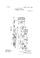
- Figure 1 is a front elevation of the machine embodying my invention.
- Fig. 2 is anend elevation 4of the said machine.
- Fig. 3 is a plan view taken on the line x :c of Fig. 1.
- Fig. 4 is an enlarged sectional view on the line y y of Fig. 3, showing the secondary feeding mechanism.
- Fig. 5 is a detail view also showing the secondary feeding mechanism'f
- Fig. 6 is a sectional IOO view through the feed-table on the line 2 z of Fig. 3, showing the primary feeding device.
- Fig. 7 is adetail view, partly in section and broken away, showing also the primary feeding device.
- Fig. 8 is an irregular sectional view on the line w w of Fig. 2, showing the counting device.
- Fig. 1 is a front elevation of the machine embodying my invention.
- Fig. 2 is anend elevation 4of the said machine.
- Fig. 3 is a plan view taken on the line x :c of
- Fig. 9 is a detail view showing the counting device.
- Fig. 10 is a detail view of the counting device, showing a modification.
- Fig. 11 is a view, partly in section, looking inthe direction of the arrow in Fig. 10.
- Fig. 12 is a sectional view through the connection 29.
- Fig. 13 is a detail view of the reciprocating device of the secondary feeding mechanism.
- 3 indicates the main shaft of the machine, from which the various members receive their motion.
- the secondary feeding mechanism is composed of a reciprocating clamping device and a stationary clamping device.
- the reci procating clamping device is composed of an upper and a lower jaw 8 and 9, the lower jaw 9 eing carried by the sleeves 10, mounted loosely on the rock-shaft 11, the said sleeves 10 further carrying the pivots 12, upon which is mounted the upper jaw 8.
- This upper lip or jaw 8 is formed with two rear projections 13 at each point where the pivots 12 are located and between which projections an intermediate member 14 is mounted, one on each pivot 12.
- Each of the said intermediate members is provided with a camsurface 15, consisting of a straight horizontal portion 16 and a curved end portion 17, with which the rollers 18 engage.
- rollers 18 are mounted upon the sleeve 19, which is adapted to reciprocate with the whole device andjwhich is further adapted to rock with the rock-shaft 11.
- a spring 2O is interposed between the projection 21 of the upper jaw or lip and the pocket or barrel 22 of the intermediate member 14.
- the relatively stationary clamping device of the secondary feeding mechanism is constructed substantially in the same way as the reciprocating clamping device except that it does not reciprocate and is different from the said reciprocating clamping device, in that it operates at periods alternating with the latter.
- 45 is a rock-shaft, one of which is located on either side of the machine and suitably mounted in the framework.
- 46 and 47 compose the upper and lower lips or jaws located one on either side of the reciprocating1clamping device and on both sides of the machine, there being four of these devices in all. As they are constructed in exactly the same way however, it is only necessary to describe one of these.
- 48 vis a pivot suitably mounted in the framework on which the upper aw or lip 46 is mounted. This up er lip or jaw has two rear projections l49, etween which the intermediate member 50 is mounted on said pivot 48.
- the said intermediate member 50 is provided with two ledges 51, which come opposite to the two rear projections 49 of the IOO IIO
- the intermediate member 50 is provided with a camsurface 55, with which engages the roller 56, mounted on the rock-shaft 45, and operates to clamp the sheet of material in substantially the same way as the reciprocating device.
- the rock-shafts 45 are operated from the same cam as the rock-shafts 11, their action, however, being opposite to or alternating with that of the reciprocating clamping device.
- Suitable connections are provided, as in the former instance, for operating these rock-shafts, comprising a rock-shaft 57, suitably connected to the pin 34 by means of crank-levers 5S and 59 and connecting-rod 60, the said rock-shaft 57 being in turn connected with the rock-shafts 45 by means of crank-levers 61 and 62 and connecting-rod 63 on one side of the machine and crank-levers 64 and 65 and connecting-rod 66 on the other side of the machine
- the stationary device of the secondary feeding mechanism is provided with adjustable stops 105, and the reciprocating device is provided with steel plugs 106, which contact with the said adjustable stops as the reciprocating device comes to the end of its motion.
- connection 29 is furthermore provided with the spring-seated plungers 107, so that as the said reciprocating device comes against the stops 105 the said yielding connection will take up any rebound and allow the said reciprocating device to stop at the same point every time. This is of great advantage when the sheet is stamp'ed very close, as it helps to preserve proper alinement.
- the parts comprising the reciprocating and stationary devices ofthe secondary feeding mechanism are so timed that the sheet is held positively at every point, the jaws 46 and 47 gripping and holding the sheet before the jaws 8 and 9 release the same.
- crank-levers 68 are a rock-shaft located at the fron-t end of the machine carrying the crank-levers 68, which connect, through the rods 69, with the reciprocating carriage 70, provided with the heel 71, sliding in the guideway 72 of the feed-table.
- the rock-shaft 67 is operated from the cam 31 at certain predetermined periods corresponding with the operation or action of the press by means of crank-lever 73, connecting rod 74, which is attached to the member 75 of the counting device 7.
- 76 is a stop for limiting the motion of the primary feeding mechanism in one direction.
- ratchet-wheel 7S or other mechanism of a similar character provided with a number of teeth or depressions.
- the crank-lever 30 After the crank-lever 30 has been operated a number of times the dog 79, engaging with it each time and moving it one step forward, the said dog will have moved the said ratchet-wheel to a point where the said ratchet-wheel is provided with a deep tooth or notch 81, into which the said dog drops by reason of the spring S2, whereby it is moved through the aperture 83 and into the member 75, to which the connecting-rod 74 is attached.
- a brake S4 is provided for steadying the motion of the parts. Vhen the crank-lever 30 moves ahead again, the dog 79 will of course have moved out of the notch S1 and the member 75 will be disconnected and the primary feeding mechanism will remain inactive until the no tch 81 comes opposite to the dog 79 again. This is a very convenient arrangement, as a new sheet can be placed upon the feed-table at any period. vWhen the sheet which is acted upon and carried step by step by the secondary feeding mechanism has been all stamped out by the machine or carried a predetermined number of steps, the primary feeding device will automatically kick the sheet on the feed-table into position withrelation to the secondary feeding mechanism, which will then carry it over the dies in the proper manner.
- this primary feeding mechanism should be variably predetermined, and I have accordingly shown in Figs. 10 and 11 a modification by means of which this can be effected.
- 85 is a shaft carrying aratchet S6 and a disk S7, having a notch SS.
- two cams are used which operate, respectively, through thelevers 89 and 90.
- the lever S9 is attached to the crank-lever 91, to which latter is adjustably secured the lever 92, which operates the secondary feeding mechanism.
- the lever 90 is attached to the crank-lever 93, to which is adjustably attached the lever 94, carrying the pawl 95, engaging the ratchet 86.
- 96 is a lever for operating the primary feeding mechanism attached to the member 97, which latter also carries the hooked lever 98. This lever 98 IlO vzo
- a secondary feeding mechanism comprising: two devices, one of which reciprocates and moves the sheet forward step by step, and the other of which holds the sheet when the reciprocating device isreturning, a primary feeding mechanism adapted to feed the sheet to the secondary feeding mechanism, and a counting device adapted to actuate the primary feeding mechanism after a variably-predetermined number of steps have been taken by the secondary feeding mechanism.
- a feeding mechanism comprising: two sets of devices, one set on either side of the machine, one of which devices reciprocates and feeds the sheet forward step by step and the other of which holds the sheet when the reciprocating device is returning, and operating means for both devices, acting alternately to clamp the sheet, connecting with both sets of devices.
- a feeding mechanism comprising: two sets of devices, one set on either side of the machine, one of which devices reciprocates and feeds the sheet forward step by step and the other of which holds the sheet when the reciprocating device is returning, and a single cam and connections for both devices, acting alternately to clamp the sheet, connecting with both sets of devices.
Landscapes
- Engineering & Computer Science (AREA)
- Mechanical Engineering (AREA)
- Press Drives And Press Lines (AREA)
Description
No. 831,765. PATENTED SEPT. 25, 1906. 0. S. BEYBR.
SHEET PEEDING MACHINE.
APPLICATION FILED 13110.26, 1903.
7 SHEETS-SHEET 1.
ls PETERS zo., WASHINGTON. D c
yPATENTED SEPT. 25, 1906. O. S. BBYER.
SHEET PEEDING MACHINE.
APPLICATION FILED DEc.2e.19oa.
'1 SHEETS-slum* z.
vwewboz 035/0700 @www TH! NaRRls PETERS co., wAsHlNcroN. n. c.
PATENTED SEPT. 25, 190.6.
0. S. BEYER. SHEET FEEDING MACHINE.
APPLIOATION FILED DBO. 26,1903.
7 SHEETS-SHEET 3.'
w00 MW rn: NaRRls PETER: cu.. wAsHmaroN. 1:'A c,
No. 831,765. PATENTED SEPT. 25, 1906. 0. Ss BEYBR.
SHEET FBBDING MACHINE.
APPLIoATIoN 4Hmm 11m26.190s.
7 SHEETS-snm 4.
PATENTED SEPT. 25, 1906.
O. S. BEYER.
SHEET FEEDING MACHINE.
APPLIC'ATIN FILED DEO.26, 1903.
7 SHEETS-SHEET 5.
No. 831.765. PATBNTED SEPT. 25, 1906.
o'.s.`BBYBR. SHEET PEBDING MAGHINB.
APPLIOATION FILED 1330.26.1903.
7 SHEETS-SHEET 6.
PATENTED SEPT. 25, 1906.
O. S. BEYER. SHEET FEEDING MACHINE.
APPLICATION FILED DEC.26,1903.
7 SHEETS-SHEET 7.
F9513 Cutoff/ump l s @Leu UNITED sTATEs PATENT oEErcE..
OTTO S. BEYER, OF EAST RUTHERFORD, NEW JERSEY, ASSIGNOR TO E. WV. BLISS COMPANY, A CORPORATION OF WEST VIRGINIA.
SHEET-FEEDING. MACHINE.
Specification of Letters Patent.
Patented Sept. 25, 1906.
Application led December 26, 1903. Serial No, 186.605.
To all whom t may concern:
Be it known that I, OTTO S. BEYEE, a citizen of the United States of America, and a resident of East Rutherford, county of Bergen, and State of New Jersey, have invented certain new and useful Improvements in Sheet-Feeding Machines, of which the following is a specification.
y invention relates generally to sheetfeeding mechanism, and has more particular reference to a mechanism adapted to be used in connection with gang-presses, although the invention isvnot necessarily limited to a combination consisting in part of a gangress.
The object of my invention is to provide means whereby a sheet of material placed upon the feed table or other supporting device of the machine, while another sheet is being acted upon by the machine will be automatically moved into position with relation to the press when the sheet being acted upon has been all stamped out. In so doing I provide a primary and a secondary feeding mechanism, the second ary feeding mechanis m being adapted to feed a sheet step by step with relation to the die, so that the latter may act upon the'said sheet. The function of the primary feeding device is to move the sheet from the feed-table or the like into proper position with relation to the secondary feeding mechanism at the proper periods-that is to say, after a sheet carried by the secondary feeding mechanism has been all stamped out by the press or after the secondary feeding mechanism has taken a number of steps the primary feeding mechanism will automatically move the said sheet from the feedtable or the like into position with relation to the secondary feeding mechanism.
In connection with the primary feeding mechanism I providea counting device or means whereby the said primary feeding mechanism will automatically move the said sheet in the manner set forth after a predetermined number of rows of blanks has been stamped out `or after a predetermined number of steps have been taken. Preferably the machine will be so constructed that a variably-predetermined number of rows of blanks can be stamped out or a variably-predetermined number of steps will be taken by the secondary feeding mechanism before the primary feeding mechanism will act, the said primary feeding mechanism being adjustable to operate at variably-predetermined periods to correspond with the action of the press.
The secondary feeding mechanism is, relatively speaking, continuously operated7 While the primary feeding mechanism is relatively intermittently operated. The secondary feeding mechanism is composed of two devices, one of which is adapted to move the sheet forward step by step,it being constructed in the present instance with a reciprocating movement moving the sheet on the forward stroke and returning without affecting the position of the sheet. The second device is merely a clamping device adapted to hold the sheet while the reciprocating device is returning in other words, to hold the sheet rigidly when it is not held by the reciprocating device. The two devices comprising the secondary feeding mechanism are self-containing, each device being mounted on a separate shaft working independently of the other, so that no undue or severe strain is put In carrying out these objects the machine comprises the features of construction and combinations of parts, as will more fully hereinafter appear.
Other objects and improvements will appear as the specification proceeds.
To facilitate the explanation of my invention, I have embodied it in a machine shown in the accompanying drawings, it being 0bvious, however, that I do not in any way limit myself to the exact structure there shown.
In the said drawings, Figure 1 is a front elevation of the machine embodying my invention. Fig. 2 is anend elevation 4of the said machine. Fig. 3 is a plan view taken on the line x :c of Fig. 1. Fig. 4 is an enlarged sectional view on the line y y of Fig. 3, showing the secondary feeding mechanism. Fig. 5 is a detail view also showing the secondary feeding mechanism'f Fig. 6 is a sectional IOO view through the feed-table on the line 2 z of Fig. 3, showing the primary feeding device. Fig. 7 is adetail view, partly in section and broken away, showing also the primary feeding device. Fig. 8 is an irregular sectional view on the line w w of Fig. 2, showing the counting device. Fig. 9 is a detail view showing the counting device. Fig. 10 is a detail view of the counting device, showing a modification. Fig. 11 is a view, partly in section, looking inthe direction of the arrow in Fig. 10. Fig. 12 is a sectional view through the connection 29. Fig. 13 is a detail view of the reciprocating device of the secondary feeding mechanism. l
Similar numerals of reference indicate corresponding parts in the different views.
1 indicates a framework of any suitable construction and adapted to support the various members comprising the machine.
2 'indicates the punches of the gang-press of any well-known or'suitable construction.
3 indicates the main shaft of the machine, from which the various members receive their motion.
4 indicates the feed-table or the like 5 5, the primary feeding mechanism 5 6, the secondary feeding mechanism, and 7 is the counting device.
The secondary feeding mechanism is composed of a reciprocating clamping device and a stationary clamping device. The reci procating clamping device is composed of an upper and a lower jaw 8 and 9, the lower jaw 9 eing carried by the sleeves 10, mounted loosely on the rock-shaft 11, the said sleeves 10 further carrying the pivots 12, upon which is mounted the upper jaw 8. This upper lip or jaw 8 is formed with two rear projections 13 at each point where the pivots 12 are located and between which projections an intermediate member 14 is mounted, one on each pivot 12. Each of the said intermediate members is provided with a camsurface 15, consisting of a straight horizontal portion 16 and a curved end portion 17, with which the rollers 18 engage. These rollers 18 are mounted upon the sleeve 19, which is adapted to reciprocate with the whole device andjwhich is further adapted to rock with the rock-shaft 11. A spring 2O is interposed between the projection 21 of the upper jaw or lip and the pocket or barrel 22 of the intermediate member 14.
It will be observed that when the rock shaft 11 is operated in one direction the rollers 18 will engage with the cam-surfaces 15 and traveling from the curved portion 17 toward the straight horizontal portion 16 of the said cam-surface will cause the intermediate member 14 to be raised, which latter, acting through the spring 20, will cause the upper 'lip or jaw 8 to move down toward the lower jaw or lip 9. On a movement in the other `direction the rollers 18 will travel from thev straight horizontal portion 16 toward the curved portion 17 of the cam-surface 15 and in so doing will move the intermediate member 14 downward, whereby the two ledges 23 of the said intermediate members will come in contact with the rear projection 13 of the upper ja'w or lip and will move the latter up and away from the lower jaw or lip. It will be understood that a device of this construction is located on each side of the machine. The lower lips or jaws of this reciprocating clamping device carry two transversely-eX- tending bars 24, which connect the two members of the said reciprocating clamping device. Attached to one of the said members is, further, the connecting-rod 25, attached to the crank-lever 26, mounted on the rockshaft 27, which receives its motion from the crank-lever 28 and connecting-rod 29, which is adjustably attached to the crank-lever 30, which in turn connects with the cam 31, from which it'receives its motion in the usual '.ihe rock-shafts 11 are rocked from the cam 32 through the rod 33, attached with its other end to the pivot 34, connecting-rod 35, and crank- levers 36 and 37, having suitable connections to the rock-shaft 38, which connects with the rock-shafts 11, so that the crank-levers 39 and 40, connecting rod 41, operate one 'side ofthe machine and cranklevers 42 and 43, connecting rod 44, operate the other side of the machine. It will thus be seen that the means which rock the two jaws 8 and 9 travel or reciprocate with the said jaws, so that the undue or severe strain is avoided, which would otherwise occur if the said jaws were rocked from another shaft. In other words, the reciprocating means and rocking shaft 11 are self-contained.
The relatively stationary clamping device of the secondary feeding mechanism is constructed substantially in the same way as the reciprocating clamping device except that it does not reciprocate and is different from the said reciprocating clamping device, in that it operates at periods alternating with the latter. It will be seen particularly from Fig. 4 that 45 is a rock-shaft, one of which is located on either side of the machine and suitably mounted in the framework. 46 and 47 compose the upper and lower lips or jaws located one on either side of the reciprocating1clamping device and on both sides of the machine, there being four of these devices in all. As they are constructed in exactly the same way however, it is only necessary to describe one of these. 48 vis a pivot suitably mounted in the framework on which the upper aw or lip 46 is mounted. This up er lip or jaw has two rear projections l49, etween which the intermediate member 50 is mounted on said pivot 48. The said intermediate member 50 is provided with two ledges 51, which come opposite to the two rear projections 49 of the IOO IIO
IIS
upper lip or jaw. 52 is a spring located in the spring-barrel 53 of the intermediate member 50 and extending into the projection 54 of the upper lip or jaw 46. The intermediate member 50 is provided with a camsurface 55, with which engages the roller 56, mounted on the rock-shaft 45, and operates to clamp the sheet of material in substantially the same way as the reciprocating device. The rock-shafts 45 are operated from the same cam as the rock-shafts 11, their action, however, being opposite to or alternating with that of the reciprocating clamping device. Suitable connections are provided, as in the former instance, for operating these rock-shafts, comprisinga rock-shaft 57, suitably connected to the pin 34 by means of crank-levers 5S and 59 and connecting-rod 60, the said rock-shaft 57 being in turn connected with the rock-shafts 45 by means of crank- levers 61 and 62 and connecting-rod 63 on one side of the machine and crank-levers 64 and 65 and connecting-rod 66 on the other side of the machine The stationary device of the secondary feeding mechanism is provided with adjustable stops 105, and the reciprocating device is provided with steel plugs 106, which contact with the said adjustable stops as the reciprocating device comes to the end of its motion. The connection 29 is furthermore provided with the spring-seated plungers 107, so that as the said reciprocating device comes against the stops 105 the said yielding connection will take up any rebound and allow the said reciprocating device to stop at the same point every time. This is of great advantage when the sheet is stamp'ed very close, as it helps to preserve proper alinement.
The parts comprising the reciprocating and stationary devices ofthe secondary feeding mechanism are so timed that the sheet is held positively at every point, the jaws 46 and 47 gripping and holding the sheet before the jaws 8 and 9 release the same.
67 is a rock-shaft located at the fron-t end of the machine carrying the crank-levers 68, which connect, through the rods 69, with the reciprocating carriage 70, provided with the heel 71, sliding in the guideway 72 of the feed-table. The rock-shaft 67 is operated from the cam 31 at certain predetermined periods corresponding with the operation or action of the press by means of crank-lever 73, connecting rod 74, which is attached to the member 75 of the counting device 7.
76 is a stop for limiting the motion of the primary feeding mechanism in one direction.
77 is a stud upon which the crank-lever 30 is mounted and to which the connecting-rod 29 is adjustably secured. Upon this stud 77 is mounted the ratchet-wheel 7S or other mechanism of a similar character provided with a number of teeth or depressions. As the sheet is fed step by step by the secondary feeding mechanism and as the crank-lever 30 moves it causes the dog 79 to engage with the teeth on the ratchet-wheel, moving the said ratchet-wheel one tooth at a time.
80 is a locking-dog for preventing the return or backward rotation of the ratchetwheel 7 8. After the crank-lever 30 has been operated a number of times the dog 79, engaging with it each time and moving it one step forward, the said dog will have moved the said ratchet-wheel to a point where the said ratchet-wheel is provided with a deep tooth or notch 81, into which the said dog drops by reason of the spring S2, whereby it is moved through the aperture 83 and into the member 75, to which the connecting-rod 74 is attached. On the next movement of the crank-lever 30 the dog 79 will not only operate the ratchet-wheel, but it will on account of its connection with the member 75 rock the said member, thereby operating the rock-shaft 67 and in turn the primary feeding device 5, kicking the sheet which has previously been placed upon the feed-table into position with relation to the secondary feeding mechanism, after which it is fed step by step by the latter. I
A brake S4 is provided for steadying the motion of the parts. Vhen the crank-lever 30 moves ahead again, the dog 79 will of course have moved out of the notch S1 and the member 75 will be disconnected and the primary feeding mechanism will remain inactive until the no tch 81 comes opposite to the dog 79 again. This is a very convenient arrangement, as a new sheet can be placed upon the feed-table at any period. vWhen the sheet which is acted upon and carried step by step by the secondary feeding mechanism has been all stamped out by the machine or carried a predetermined number of steps, the primary feeding device will automatically kick the sheet on the feed-table into position withrelation to the secondary feeding mechanism, which will then carry it over the dies in the proper manner. It is preferable that the operation of this primary feeding mechanism should be variably predetermined, and I have accordingly shown in Figs. 10 and 11 a modification by means of which this can be effected. In these modifications, 85 is a shaft carrying aratchet S6 and a disk S7, having a notch SS. In this instance two cams are used which operate, respectively, through thelevers 89 and 90. The lever S9 is attached to the crank-lever 91, to which latter is adjustably secured the lever 92, which operates the secondary feeding mechanism. The lever 90 is attached to the crank-lever 93, to which is adjustably attached the lever 94, carrying the pawl 95, engaging the ratchet 86. 96 is a lever for operating the primary feeding mechanism attached to the member 97, which latter also carries the hooked lever 98. This lever 98 IlO vzo
carries a doo 99 or other device which rests upon the diszk 87 and is provided with a hook 100, adapted to engage and disengage with the pin 101 or other device carried by the crank-lever 91.
It will be understood that whenA the ratchet 86 has been turned a sufficient distance the disk 87 will come opposite to the dog 99, which will then drop into the notch 88, whereupon the hook 100 will engage with the pin 101, thereby operating the lever 96 for the primary feeding mechanism on the next movement of the crank-lever 91. When it is desired to vary the relation of the parts, it is only necessary to replace the ratchet 86 with one having a different number of teeth and to adjust the strokes of the levers 92 and 94. In order to prevent the tin from buckling and to keep it flat on the feed-table, I employ magnets, as 108, on the under side of the said feed-table.
Having thus described my invention, what I claim is- 1. In a machine of the character set forth, the combination of a secondary feeding mechanism comprising: two devices, one of which reciprocates and moves the sheet forward step by step, and the other of which holds the sheet when the reciprocating device isreturning, a primary feeding mechanism adapted to feed the sheet to the secondary feeding mechanism, and a counting device adapted to actuate the primary feeding mechanism after a variably-predetermined number of steps have been taken by the secondary feeding mechanism.
2. In a machine of the character set forth, the combination of a feeding mechanism comprising: two sets of devices, one set on either side of the machine, one of which devices reciprocates and feeds the sheet forward step by step and the other of which holds the sheet when the reciprocating device is returning, and operating means for both devices, acting alternately to clamp the sheet, connecting with both sets of devices.
' 8, In a machine of the character set forth, the combination of a feeding mechanism comprising: two sets of devices, one set on either side of the machine, one of which devices reciprocates and feeds the sheet forward step by step and the other of which holds the sheet when the reciprocating device is returning, and a single cam and connections for both devices, acting alternately to clamp the sheet, connecting with both sets of devices.
' 4. In a machine of the character set forth, the combination of two rock-shafts extending parallel to each other, a reciprocating vclamping device composed of two jaws carried by one of said rock-shafts, means for rocking one of said jaws from the rock-shaft carrying the same, means for reciprocating both jaws on said rock-shaft, a stationary clamping device composed of two jaws, and
means for rocking one of the last-mentioned jaws from the other rock-shaft.
5. In a machine'of the character set forth,
the combination of two rock-shafts extending parallel to each other, a reciprocating clamping device composed of two jaws carried by one of said rock-shafts, means for rocking one of said jaws from the rock-shaft carrying the same, means for reciprocating both jaws on said rock-shaft, a stationary clamping device composed of two jaws, means for rocking one of the last-mentioned jaws from the other rock-shaft, and means for rocking said rock-shafts in opposite directions. 6. The combination of a rock-shaft, two jaws suitably mounted on the said rock-shaft, means for reciprocating the two jaws on the said rock-shaft, and means for rocking one of said jaws from the said rock-shaft.
7. The combination of a rock-shaft, a lower jaw, sleeves loosely mounted `on the said rock-shaft carrying the said lower jaw, an upper jaw, pivots supporting the said upper jaw, intermediate members adapted to be rocked from the rock-shaft and adapted to impart theirmotion to the upper jaw, and means for reciprocating the two jaws.
8. The combination of a rock-shaft, a lower jaw, sleeves loosely mounted on said rock-shaft carrying the lower jaw, an upper jaw, pivots supporting the said upper jaw, intermediate members carried on said pivots, means for rocking the intermediate mem,- bers from the rock-shaft and for imparting their motion to the upper jaw, and means for reciprocating the said jaws,
9. rlhe combination of a rock-shaft, a lower jaw, sleeves loosely mounted on the said rock-shaft carrying the said lower jaw, an upper jaw, pivots supporting the said upper jaw, intermediate members carried on the said pivots, cam-surfaces carried on the intermediate members, rollers mounted on the rock-shaft for engaging with the said cam-surfaces to rock the said intermediate member, rearwardly-extending projections on the upper jaw, corresponding ledgeson the intermediate members, and a spring interposed between the intermediate members and the upper jaw whereby the rocking motion of the said intermediate member is imparted to the said jaws, and means for reciprocating the said jaws.
10. In a machine of the character' set forth, the combination of a rock-shaft, stationary lower jaw, an upper aw, a pivot supporting the said upper jaw, a sleeve loosely mounted on the said rock-shaft carrying the said pivot and lower jaw, and an intermediate member adapted to be rocked from the rock-shaft and to impart its motion to the upper jaw.
11. In a machine of the character set IOO IIO
forth, the combination with a rook-shaft, a lower stationary jaw, an upper jaw, a pivot supporting the said upper jaw, a sleeve loosely mounted on the said roe vshaft and carrying the said pivot and lower jaw, an intermediate member carried on the said pivot, and means for rocking the intermediate member from the rock-shaft and for imparting its motion to the upper j aw.
12. In a machine of the character set forth, the combination of a rock-shaft, a lower stationary jaw, an upper jaw, a pivot supporting the said upper jaw, a sleeve loosely mounted on the said rock-shaft and carrying the said pivot and lower jaw, an intermediate member carried on the said pivot, a cam-surface on the said intermediate member, a roller mounted on the rock-shaft, and adapted to engage with the said cam-surface on the intermediate member, rearwardly-extending projections on the upper jaw, corresponding ledges on the intermediate member, and a spring interposed between the said upper jaw and the intermediate member whereby the motion of the said intermediate member is imparted to the upper jaw.
13. The combination of a rock-shaft, a lower jaw, sleeves loosely mounted on the said rock-shaft carrying the said lower jaw, an upper jaw, pivots supporting the said upper jaw, intermediate members adapted to be rocked from the rock-shaft and adapted to impart their motion to the upper jaw and means for reciprocating the two jaws and the members for rocking the upper jaw.
14. The combination or' a rocl -shaft, a lower jaw, sleeves loosely mounted on said roelvshaft carrying the lower jaw, an upper jaw, pivots supportingl the said upper jaw, intermediate members carried on said pivots, means for rocking the intermediate members from the rock-shaft and for imparting their motion to the upper jaw, and means for reciprocatingl the said jaws and the members for rocking the upper jaw.
15. The combination of a rock-shaft, a lower jaw, sleeves loosely mounted on the said rock-shaft carrying the said lower jaw, an upper jaw, pivots supporting the said upper jaw, intermediate members carried on the said pivots, cam-surfaces carried on the intermediate members, rollers m'ounted on the rock-shaft for engaging with the said camsurfaces to rock the said intermediate members, rearwarilly-extending projections on the upper jaw, correspondingl ledges on the intermediate members, and a spring interposed between the intermediate members and the upper jaw whereby the rocking m0- tion of the said intermediate members is imparted to the said jaws, and means for reciprocating the said jaws and the members 'for rocking the upper jaw.
16. The combination of a rock-shaft, two jaws suitably mounted on the said rockshaft, means l' or rocking one of the said jaws from the rock-shaft, and means for reciproeating the jaws and means for rocking the I same in unison on the said rock-shaft.
Signed at Brooklyn, New York, this .12th day of December, 1903.
OTTO S. BEYER.
Witnesses:
W. E. MURDooK, FRED. H. MoGAl-IEL.
Priority Applications (1)
| Application Number | Priority Date | Filing Date | Title |
|---|---|---|---|
| US18660503A US831765A (en) | 1903-12-26 | 1903-12-26 | Sheet-feeding machine. |
Applications Claiming Priority (1)
| Application Number | Priority Date | Filing Date | Title |
|---|---|---|---|
| US18660503A US831765A (en) | 1903-12-26 | 1903-12-26 | Sheet-feeding machine. |
Publications (1)
| Publication Number | Publication Date |
|---|---|
| US831765A true US831765A (en) | 1906-09-25 |
Family
ID=2900240
Family Applications (1)
| Application Number | Title | Priority Date | Filing Date |
|---|---|---|---|
| US18660503A Expired - Lifetime US831765A (en) | 1903-12-26 | 1903-12-26 | Sheet-feeding machine. |
Country Status (1)
| Country | Link |
|---|---|
| US (1) | US831765A (en) |
Cited By (3)
| Publication number | Priority date | Publication date | Assignee | Title |
|---|---|---|---|---|
| US3099180A (en) * | 1957-08-29 | 1963-07-30 | Niagara Machine & Tool Works | Feed roll release means for power presses |
| US3793972A (en) * | 1972-08-04 | 1974-02-26 | Nat Can Corp | Method and apparatus for feeding a sheet metal web |
| US3979983A (en) * | 1974-06-05 | 1976-09-14 | U.S. Amada, Ltd. | Workpiece-handling apparatus |
-
1903
- 1903-12-26 US US18660503A patent/US831765A/en not_active Expired - Lifetime
Cited By (3)
| Publication number | Priority date | Publication date | Assignee | Title |
|---|---|---|---|---|
| US3099180A (en) * | 1957-08-29 | 1963-07-30 | Niagara Machine & Tool Works | Feed roll release means for power presses |
| US3793972A (en) * | 1972-08-04 | 1974-02-26 | Nat Can Corp | Method and apparatus for feeding a sheet metal web |
| US3979983A (en) * | 1974-06-05 | 1976-09-14 | U.S. Amada, Ltd. | Workpiece-handling apparatus |
Similar Documents
| Publication | Publication Date | Title |
|---|---|---|
| US831765A (en) | Sheet-feeding machine. | |
| US3462056A (en) | Stock feeder | |
| US723400A (en) | Feed mechanism. | |
| US765414A (en) | Feeding-machine and printing-press controlling mechanism. | |
| US938876A (en) | Automatic feeding mechanism for presses. | |
| US653955A (en) | Triple-die press. | |
| US784415A (en) | Automatic feed for die-presses, &c. | |
| US720547A (en) | Sheet separating and feeding mechanism for printing or other machines. | |
| US738103A (en) | Feed mechanism. | |
| US765911A (en) | Feeding mechanism for stapling-machines. | |
| US705450A (en) | Nail-machine. | |
| US142825A (en) | Improvement | |
| US335154A (en) | Starling-machine | |
| US2470102A (en) | Conversion unit for coining presses | |
| US544075A (en) | Printing-press | |
| US1051240A (en) | Typograph. | |
| US678901A (en) | Can-cutting machine. | |
| US594751A (en) | Writing- pens | |
| US1119857A (en) | Sheet-feeding device. | |
| US1059325A (en) | Cell-case machine. | |
| US503264A (en) | davidson | |
| US719939A (en) | Button-setting machine. | |
| US386076A (en) | leayitt | |
| US1086525A (en) | Sheet-metal punching and forming machine. | |
| US631203A (en) | Nail-machine. |