US20240297453A1 - Terminal - Google Patents
Terminal Download PDFInfo
- Publication number
- US20240297453A1 US20240297453A1 US18/572,777 US202218572777A US2024297453A1 US 20240297453 A1 US20240297453 A1 US 20240297453A1 US 202218572777 A US202218572777 A US 202218572777A US 2024297453 A1 US2024297453 A1 US 2024297453A1
- Authority
- US
- United States
- Prior art keywords
- resilient
- piece
- wall
- contact
- tab
- Prior art date
- Legal status (The legal status is an assumption and is not a legal conclusion. Google has not performed a legal analysis and makes no representation as to the accuracy of the status listed.)
- Granted
Links
Images



Classifications
-
- H—ELECTRICITY
- H01—ELECTRIC ELEMENTS
- H01R—ELECTRICALLY-CONDUCTIVE CONNECTIONS; STRUCTURAL ASSOCIATIONS OF A PLURALITY OF MUTUALLY-INSULATED ELECTRICAL CONNECTING ELEMENTS; COUPLING DEVICES; CURRENT COLLECTORS
- H01R13/00—Details of coupling devices of the kinds covered by groups H01R12/70 or H01R24/00 - H01R33/00
- H01R13/02—Contact members
- H01R13/10—Sockets for co-operation with pins or blades
- H01R13/11—Resilient sockets
- H01R13/113—Resilient sockets co-operating with pins or blades having a rectangular transverse section
Definitions
- the present disclosure relates to a terminal.
- a terminal fitting used in an automotive vehicle or the like is conventionally known from Japanese Patent Laid-Open Publication No. 2006-080004 (Patent Document 1 below).
- This terminal fitting is provided with a rectangular tube portion, into which a tab of a mating terminal is inserted from front.
- a resilient contact piece is provided on a bottom plate of the rectangular tube portion, and a receiving portion projecting downward is provided on an upper plate of the rectangular tube portion.
- a pair of left and right side plates of the rectangular tube portion are formed with holding portions cantilevered forward and curved to bulge inwardly of the rectangular tube portion.
- the tab inserted into the rectangular tube portion is sandwiched in a thickness direction between the resilient contact piece and the receiving portion.
- a pair of left and right holding portions hold a tip part of the tab to prevent this tip part from being displaced in a lateral direction with respect to the rectangular tube portion by contacting the tab at a position closer to a tip than a contact portion with the resilient contact piece.
- the insertion of the mating terminal into the rectangular tube portion is possibly hindered by the holding portion being bent inwardly of the rectangular tube portion by an external force.
- the present disclosure is directed to a terminal with a rectangular tube portion, a tab of a mating terminal being inserted into the rectangular tube portion from front, a resilient contact piece provided in the rectangular tube portion, and a receiving portion provided in the rectangular tube portion, the receiving portion sandwiching the tab together with the resilient contact piece,
- the rectangular tube portion including a first wall provided with the resilient contact piece, a second wall provided with the receiving portion and a pair of side walls connecting both side edges of the first wall and both side edges of the second wall, a facing direction of the pair of side walls being a first direction, at least one of the pair of side walls including a resilient piece for suppressing a movement of the tab in the first direction by pressing a side edge of the tab inwardly of the recontact portion in the first direction, the resilient piece including a contact portion disposed to face a side edge of the resilient contact piece in the first direction, and a movement of a tip part of the resilient piece inwardly of the rectangular tube portion in the first direction being suppressed by contact of the contact portion with the
- a terminal capable of making it difficult to hinder the insertion of a mating terminal into a rectangular tube portion and ensuring connection reliability to the mating terminal under a vibration environment.
- FIG. 1 is a perspective view of a terminal according to a first embodiment.
- FIG. 2 is a front view of the terminal.
- FIG. 3 is a left side view of the terminal.
- FIG. 4 is a section along A-A of FIG. 2 .
- FIG. 5 is a view in cross-section along A-A of FIG. 2 showing a state where a tab of a mating terminal is inserted in a rectangular tube portion.
- FIG. 6 is a section along B-B of FIG. 2 .
- FIG. 7 is a section along C-C of FIG. 3 .
- FIG. 8 is a view in cross-section along C-C of FIG. 3 showing the state where the tab of the mating terminal is inserted in the rectangular tube portion.
- FIG. 9 is a front view of a terminal according to a second embodiment.
- FIG. 10 is a left side view of the terminal.
- FIG. 11 is a section along D-D of FIG. 9 .
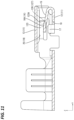
- FIG. 12 is a section along E-E of FIG. 10 .
- the terminal of the present disclosure is provided with a rectangular tube portion, a tab of a mating terminal being inserted into the rectangular tube portion from front, a resilient contact piece provided in the rectangular tube portion, and a receiving portion provided in the rectangular tube portion, the receiving portion sandwiching the tab together with the resilient contact piece,
- the rectangular tube portion including a first wall provided with the resilient contact piece, a second wall provided with the receiving portion and a pair of side walls connecting both side edges of the first wall and both side edges of the second wall, a facing direction of the pair of side walls being a first direction, at least one of the pair of side walls including a resilient piece for suppressing a movement of the tab in the first direction by pressing a side edge of the tab inwardly of the recontact portion in the first direction, the resilient piece including a contact portion disposed to face a side edge of the resilient contact piece in the first direction, and a movement of a tip part of the resilient piece inwardly of the rectangular tube portion in the first direction being suppressed by contact of the contact portion with the side
- the resilient piece includes a body portion long in a front-rear direction and an extending portion extending toward the first wall from a tip part of the body portion, and the extending portion includes the contact portion.
- a contact point portion having a spherical shape, projecting toward the second wall and to be contacted by a surface of the tab facing the first wall is provided on an outer surface of the resilient contact piece on the second wall side, and the extending portion is disposed forward of a top of the contact point portion.
- the extending portion is disposed forward of the top of the contact point portion to be contacted by the surface of the tab facing the first wall, the contact point portion is hardly damaged due to the contact of the contact portion of the extending portion with the side edge of the resilient contact piece. Therefore, the connection reliability of the terminal and the mating terminal is easily ensured.
- only one of the pair of side walls includes the resilient piece, and the other of the pair of side walls includes a pushing portion for sandwiching the tab in the first direction together with the resilient piece.
- the connection reliability of the terminal and the mating terminal can be ensured also under a vibration environment. Since the resilient piece is provided only in one of the pair of side walls, the tip part of the resilient piece is less likely to move inwardly of the rectangular portion as compared to the case where resilient pieces are provided in both of the pair of side walls.
- a terminal 10 of this embodiment is, for example, mounted in a vehicle such as an automotive vehicle and used under a vibration environment where vibration is generated.
- a direction indicated by an arrow Z is referred to as an upward direction
- a direction indicated by an arrow X is referred to as a forward direction
- a direction indicated by an arrow Y is referred to as a leftward direction.
- the terminal 10 is formed by press-working and bending an electrically conductive metal plate material. As shown in FIG. 1 , the terminal 10 is provided with a rectangular tube portion 11 open in a front-rear direction in a substantially front half part of the terminal 10 and a wire barrel B 1 and an insulation barrel B 2 disposed behind the rectangular tube portion 11 . As shown in FIG. 5 , a tab 41 of a mating terminal 40 is inserted into the rectangular tube portion 11 from front.
- the wire barrel B 1 is crimped to a core wire of an unillustrated coated wire
- the insulation barrel B 2 is crimped to an insulation coating of the unillustrated coated wire.
- the rectangular tube portion 11 is provided with a first wall 12 disposed on a lower side of the rectangular tube portion 11 , a second wall 13 facing the first wall 12 and a pair of side walls 14 connecting both side edges of the first wall 12 and both side edges of the second wall 13 .
- a facing direction of the pair of side walls 14 is a lateral direction (an example of a first direction).
- One of the pair of side walls 14 is a third wall 14 A disposed on a left side of the rectangular tube portion 11 .
- the other side wall 14 is a fourth wall 14 B disposed on a right side of the rectangular tube portion 11 .
- the top 16 A of the contact point portion 16 is disposed at a position, which is a center position in the lateral direction and substantially 2 ⁇ 3 from the front end of the contact point portion 16 in a front-rear direction.
- excessive deformation preventing portions 17 for suppressing downward deformation of the resilient contact piece 15 are provided below the resilient contact piece 15 of the first wall 12 .
- a pair of the excessive deformation preventing portions 17 are formed by cutting and raising below right and left end parts of the resilient contact piece 15 .
- the first wall 12 includes a locking portion 18 for locking the terminal 10 to an unillustrated housing.
- the second wall 13 is provided with a receiving portion 19 projecting downward from the lower surface of the second wall 13 .
- the receiving portion 19 is formed by being struck downward.
- the receiving portion 19 is composed of a pair of ridge portions 20 arranged in the lateral direction.
- the ridge portion 20 is formed to extend in the front-rear direction.
- An interval in the vertical direction between the lower end of the ridge portion 20 and the top 16 A of the contact point portion 16 is set to be smaller than a vertical dimension of the tab 41 .
- FIG. 8 with the tab 41 inserted in the rectangular tube portion 11 , the tab 41 is sandwiched in the vertical direction between the receiving portion 19 and the contact point portion 16 of the resilient contact piece 15 . In this way, the terminal 10 and the mating terminal 40 are electrically connected.
- the third wall 14 A is provided with a resilient piece 23 by being cut and raised.
- the resilient piece 23 is cantilevered forward from a rear part of the third wall 14 A.
- the resilient piece 23 is resiliently deformable in the lateral direction with a base end of a rear end part substantially as a fulcrum.
- the resilient piece 23 is provided to be located more inwardly of the rectangular tube portion 11 , i.e. more rightward toward a front side as a whole.
- a tip part 23 A which is a front end part of the resilient piece 23 , is bent outwardly of the rectangular tube portion 11 , i.e. leftward.
- a rightmost part of the resilient piece 23 serves as a pressing portion 24 .
- the pressing portion 24 is disposed at a position near the contact point portion 16 of the resilient contact piece 15 in the front-rear direction. As shown in FIG. 5 , the pressing portion 24 presses a side edge of the tab 41 inserted into the rectangular tube portion 11 .
- the resilient piece 23 includes a contact portion 27 disposed to face a side edge 15 A (left side edge in this embodiment) of the resilient contact piece 15 in the lateral direction.
- the contact portion 27 comes into contact with the side edge 15 A of the resilient piece 15 .
- the contact portion 27 is disposed on the side of the tip part 23 A of the resilient piece 23 .
- the pressing portion 24 may double as the contact portion 27 (see FIG. 7 ).
- the fourth wall 14 B is provided with a pushing portion 28 projecting leftward from the left surface of the fourth wall 14 B.
- the pushing portion 28 is formed by being struck leftward.
- the pushing portion 28 is long in the front-rear direction and has a rectangular shape short in the vertical direction.
- the pushing portion 28 and the pressing portion 24 of the resilient piece 23 are disposed at positions between the lower end of the receiving portion 19 and a position somewhat below the upper surface of the resilient contact piece 15 in the vertical direction.
- An interval in the lateral direction between the pushing portion 28 and the pressing portion 24 is set to be slightly smaller than a lateral dimension of the tab 41 .
- the tab 41 As shown in FIGS. 5 and 8 , with the tab 41 inserted in the rectangular tube portion 11 , the tab 41 is sandwiched in the lateral direction between the pushing portion 28 and the pressing portion 24 . In this way, a movement of the tab 41 in the lateral direction can be suppressed also under a vibration environment such as an automotive vehicle. Thus, it is possible to suppress the abrasion of the tab 41 , the resilient contact piece 15 and the receiving portion 19 due to a movement of the tab 41 in the lateral direction and ensure the connection reliability of the terminal 10 and the mating terminal 40 .
- projecting pieces 29 projecting downward of the rectangular tube portion 11 are respectively provided on rear parts of the pair of side walls 14 .
- the projecting pieces 29 prevent the terminal 10 from being inserted in a vertically inverted posture into the housing and guide the insertion of the terminal into the housing by entering grooves provided in the housing when the terminal 10 is accommodated into the unillustrated housing.
- the terminal 10 is configured as described above. A movement of the tip part 23 A of the resilient piece 23 of the terminal 10 in the lateral direction is described below.
- the resilient piece 23 of the terminal 10 is provided by cutting and raising the third wall 14 A, and exposed to outside. Thus, there is a possible case where the tip part 23 A of the resilient piece 23 moves inwardly of the rectangular tube portion 11 by receiving an external force.
- the tip part 23 A of the resilient piece 23 is provided with the contact portion 27 , and the contact portion 27 is disposed to face the side edge 15 A of the resilient contact piece 15 in the lateral direction.
- the contact portion 27 and the side edge 15 A of the resilient contact piece 15 come into contact, whereby the tip part 23 A of the resilient piece 23 is suppressed from moving inwardly of the rectangular tube portion 11 (rightward) further than the side edge 15 A of the resilient contact piece 15 . Therefore, it can be, for example, suppressed that the resilient piece 23 rides on the upper surface of the resilient contact piece 15 to hinder the insertion of the tab 41 of the mating terminal 40 into the rectangular tube portion 11 .
- the terminal 10 according to the first embodiment is provided with the rectangular portion 11 , into which the tab 41 of the mating terminal 40 is inserted from front, the resilient contact piece 15 provided in the rectangular portion 11 and the receiving portion 19 provided in the rectangular portion 11 and configured to sandwich the tab 41 together with the resilient contact piece 15 .
- the rectangular portion 11 includes the first wall 12 provided with the resilient contact piece 15 , the second wall 13 provided with the receiving portion 19 , and the pair of side walls 14 connecting the both side edges of the first wall 12 and the both side edges of the second wall 13 .
- the facing direction of the pair of side walls 14 is the first direction.
- At least one of the pair of side walls 14 includes the resilient piece 23 for suppressing a movement of the tab 41 in the first direction by pressing the side edge of the tab 41 inwardly of the rectangular portion 11 in the first direction.
- the resilient piece 23 includes the contact portion 27 disposed to face the side edge 15 A of the resilient contact piece 15 in the first direction. A movement of the tip part 23 A of the resilient piece 23 inwardly of the rectangular portion 11 in the first direction is suppressed by the contact of the contact portion 27 and the side edge 15 A of the resilient contact piece 15 .
- only one (third wall 14 A) of the pair of side walls 14 is provided with the resilient piece 23
- the other (fourth wall 14 B) of the pair of side walls 14 is provided with the pushing portion 28 for sandwiching the tab 41 in the first direction together with the resilient piece 23 .
- the connection reliability of the terminal 10 and the mating terminal 40 can be ensured also under a vibration environment. Since the resilient piece 23 is provided in only one (third wall 14 A) of the pair of side walls 14 , the tip part 23 A of the resilient piece is less likely to move inwardly of the rectangular portion 11 as compared to the case where resilient pieces are provided in both of a pair of side walls.
- a second embodiment of the present disclosure is described with reference to FIGS. 9 to 12 .
- a terminal 110 of the second embodiment is configured similarly to the terminal 10 of the first embodiment except the configuration of a resilient piece 123 .
- the same members as in the first embodiment are denoted by reference signs used in the first embodiment and the same configurations, functions and effects as in the first embodiment are not described below.
- the resilient piece 123 is substantially L-shaped in a side view and includes a body portion 125 long in the front-rear direction and an extending portion 126 extending toward a first wall 12 (i.e. downward) from a tip part of the body portion 125 .
- the extending portion 126 is a lower part of a tip part 123 A of the resilient piece 123 .
- the extending portion 126 includes a contact portion 127 disposed to face a side edge 15 A (left side edge in this embodiment) of a resilient contact piece 15 in the lateral direction. If the tip part 123 A of the resilient piece 123 is moved inwardly of a rectangular portion 11 (rightward) by an external force, the contact portion 127 and the side edge 15 A of the resilient contact piece 15 come into contact, whereby the tip part 123 A of the resilient piece 123 is suppressed from moving further rightward than the side edge 15 A of the resilient piece 15 . Therefore, it can be, for example, suppressed that the resilient piece 123 rides on the upper surface of the resilient contact piece 15 to hinder the insertion of a tab 41 of a mating terminal 40 into the rectangular tube portion 11 .
- a contact part of the side edge 15 A of the resilient contact piece 15 and the contact portion 127 is enlarged by providing the extending portion 126 .
- the resilient piece 23 includes no extending portion, for example, as in the first embodiment, it is difficult to enlarge a contact part of the contact portion 27 and the side edge 15 A of the resilient contact piece 15 without changing a vertical dimension of the resilient piece 23 (see FIGS. 2 and 7 ).
- the top 16 A of the contact point portion 16 is a part to be contacted by the lower surface of the tab 41 and associated with the connection of the terminal 110 and the mating terminal 40 , the connection reliability of the terminal 110 and the mating terminal 40 is easily ensured according to this embodiment.
- the contact part of the contact portion 127 and the side edge 15 A of the resilient contact piece 15 is easily enlarged.
- a movement of the tip part 123 A of the resilient piece 123 inwardly of the rectangular portion 11 can be further suppressed.
- the contact point portion 16 having a spherical shape, projecting toward a second wall 13 and to be contacted by the surface (lower surface) of the tab 41 facing the first wall 12 is provided on the outer surface (upper surface) of the resilient contact piece 15 on the side of the second wall 13 , and the extending portion 126 is disposed forward of the top 16 A of the contact point portion 16 .
- the contact point portion 16 is hardly damaged due to the contact of the contact portion 127 of the extending portion 126 with the side edge 15 A of the resilient contact piece 15 . Therefore, the connection reliability of the terminal 110 and the mating terminal 40 is easily ensured.
- the resilient piece 23 , 123 is provided only in the third wall 14 A and the pushing portion 28 provided on the fourth wall 14 B in the above embodiments, there is no limitation to this and a resilient piece may be provided in each of a pair of side walls and a tab may be sandwiched in the first direction by a pair of the resilient pieces.
- resilient piece 23 , 123 is cantilevered forward from the rear part of the third wall 14 A in the above embodiments, there is no limitation to this.
- a resilient piece may be cantilevered rearward from a front part of a third wall.
Landscapes
- Connector Housings Or Holding Contact Members (AREA)
Abstract
Description
- The present disclosure relates to a terminal.
- A terminal fitting used in an automotive vehicle or the like is conventionally known from Japanese Patent Laid-Open Publication No. 2006-080004 (Patent Document 1 below). This terminal fitting is provided with a rectangular tube portion, into which a tab of a mating terminal is inserted from front. A resilient contact piece is provided on a bottom plate of the rectangular tube portion, and a receiving portion projecting downward is provided on an upper plate of the rectangular tube portion. A pair of left and right side plates of the rectangular tube portion are formed with holding portions cantilevered forward and curved to bulge inwardly of the rectangular tube portion. The tab inserted into the rectangular tube portion is sandwiched in a thickness direction between the resilient contact piece and the receiving portion. A pair of left and right holding portions hold a tip part of the tab to prevent this tip part from being displaced in a lateral direction with respect to the rectangular tube portion by contacting the tab at a position closer to a tip than a contact portion with the resilient contact piece. Thus, abrasion between the tab and the rectangular tube portion and between the tab and the resilient contact piece can be suppressed. Therefore, the connection reliability of the terminal fitting and the mating terminal can be ensured also under a vibration environment such as an automotive vehicle.
-
-
- Patent Document 1: JP 2006-080004 A
- However, in the above configuration, the insertion of the mating terminal into the rectangular tube portion is possibly hindered by the holding portion being bent inwardly of the rectangular tube portion by an external force.
- The present disclosure is directed to a terminal with a rectangular tube portion, a tab of a mating terminal being inserted into the rectangular tube portion from front, a resilient contact piece provided in the rectangular tube portion, and a receiving portion provided in the rectangular tube portion, the receiving portion sandwiching the tab together with the resilient contact piece, the rectangular tube portion including a first wall provided with the resilient contact piece, a second wall provided with the receiving portion and a pair of side walls connecting both side edges of the first wall and both side edges of the second wall, a facing direction of the pair of side walls being a first direction, at least one of the pair of side walls including a resilient piece for suppressing a movement of the tab in the first direction by pressing a side edge of the tab inwardly of the recontact portion in the first direction, the resilient piece including a contact portion disposed to face a side edge of the resilient contact piece in the first direction, and a movement of a tip part of the resilient piece inwardly of the rectangular tube portion in the first direction being suppressed by contact of the contact portion with the side edge of the resilient contact piece.
- According to the present disclosure, it is possible to provide a terminal capable of making it difficult to hinder the insertion of a mating terminal into a rectangular tube portion and ensuring connection reliability to the mating terminal under a vibration environment.
-
FIG. 1 is a perspective view of a terminal according to a first embodiment. -
FIG. 2 is a front view of the terminal. -
FIG. 3 is a left side view of the terminal. -
FIG. 4 is a section along A-A ofFIG. 2 . -
FIG. 5 is a view in cross-section along A-A ofFIG. 2 showing a state where a tab of a mating terminal is inserted in a rectangular tube portion. -
FIG. 6 is a section along B-B ofFIG. 2 . -
FIG. 7 is a section along C-C ofFIG. 3 . -
FIG. 8 is a view in cross-section along C-C ofFIG. 3 showing the state where the tab of the mating terminal is inserted in the rectangular tube portion. -
FIG. 9 is a front view of a terminal according to a second embodiment. -
FIG. 10 is a left side view of the terminal. -
FIG. 11 is a section along D-D ofFIG. 9 . -
FIG. 12 is a section along E-E ofFIG. 10 . - First, embodiments of the present disclosure are listed and described.
- (1) The terminal of the present disclosure is provided with a rectangular tube portion, a tab of a mating terminal being inserted into the rectangular tube portion from front, a resilient contact piece provided in the rectangular tube portion, and a receiving portion provided in the rectangular tube portion, the receiving portion sandwiching the tab together with the resilient contact piece, the rectangular tube portion including a first wall provided with the resilient contact piece, a second wall provided with the receiving portion and a pair of side walls connecting both side edges of the first wall and both side edges of the second wall, a facing direction of the pair of side walls being a first direction, at least one of the pair of side walls including a resilient piece for suppressing a movement of the tab in the first direction by pressing a side edge of the tab inwardly of the recontact portion in the first direction, the resilient piece including a contact portion disposed to face a side edge of the resilient contact piece in the first direction, and a movement of a tip part of the resilient piece inwardly of the rectangular tube portion in the first direction being suppressed by contact of the contact portion with the side edge of the resilient contact piece.
- According to this configuration, since a movement of the tab in the first direction is suppressed by the resilient piece, the abrasion of the tab, the resilient contact piece and the receiving portion is suppressed also under a vibration environment and the connection reliability of the terminal and the mating terminal can be ensured. Since a movement of the tip part of the resilient piece inwardly of the rectangular portion in the first direction can be suppressed by the contact of the contact portion of the resilient piece with the side edge of the resilient contact piece, the insertion of the mating terminal into the rectangular portion is hardly hindered.
- (2) Preferably, the resilient piece includes a body portion long in a front-rear direction and an extending portion extending toward the first wall from a tip part of the body portion, and the extending portion includes the contact portion.
- According to this configuration, a contact part of the contact portion and the side edge of the resilient contact piece is easily enlarged. Thus, a movement of the tip part of the resilient piece inwardly of the rectangular tube portion can be further suppressed.
- (3) Preferably, a contact point portion having a spherical shape, projecting toward the second wall and to be contacted by a surface of the tab facing the first wall is provided on an outer surface of the resilient contact piece on the second wall side, and the extending portion is disposed forward of a top of the contact point portion.
- According to this configuration, since the extending portion is disposed forward of the top of the contact point portion to be contacted by the surface of the tab facing the first wall, the contact point portion is hardly damaged due to the contact of the contact portion of the extending portion with the side edge of the resilient contact piece. Therefore, the connection reliability of the terminal and the mating terminal is easily ensured.
- (4) Preferably, only one of the pair of side walls includes the resilient piece, and the other of the pair of side walls includes a pushing portion for sandwiching the tab in the first direction together with the resilient piece.
- According to this configuration, since a movement of the tab in the first direction is suppressed by the resilient piece and the pushing portion, the connection reliability of the terminal and the mating terminal can be ensured also under a vibration environment. Since the resilient piece is provided only in one of the pair of side walls, the tip part of the resilient piece is less likely to move inwardly of the rectangular portion as compared to the case where resilient pieces are provided in both of the pair of side walls.
- Hereinafter, embodiments of the present disclosure are described. The present disclosure is not limited to these illustrations, but is represented by claims and intended to include all changes in the scope of claims and in the meaning and scope of equivalents.
- A first embodiment of the present disclosure is described with reference to FIGS. 1 to 8. A
terminal 10 of this embodiment is, for example, mounted in a vehicle such as an automotive vehicle and used under a vibration environment where vibration is generated. In the following description, a direction indicated by an arrow Z is referred to as an upward direction, a direction indicated by an arrow X is referred to as a forward direction and a direction indicated by an arrow Y is referred to as a leftward direction. - The
terminal 10 is formed by press-working and bending an electrically conductive metal plate material. As shown inFIG. 1 , theterminal 10 is provided with arectangular tube portion 11 open in a front-rear direction in a substantially front half part of theterminal 10 and a wire barrel B1 and an insulation barrel B2 disposed behind therectangular tube portion 11. As shown inFIG. 5 , atab 41 of amating terminal 40 is inserted into therectangular tube portion 11 from front. The wire barrel B1 is crimped to a core wire of an unillustrated coated wire, and the insulation barrel B2 is crimped to an insulation coating of the unillustrated coated wire. - As shown in
FIGS. 2 and 7 , therectangular tube portion 11 is provided with afirst wall 12 disposed on a lower side of therectangular tube portion 11, asecond wall 13 facing thefirst wall 12 and a pair of side walls 14 connecting both side edges of thefirst wall 12 and both side edges of thesecond wall 13. A facing direction of the pair of side walls 14 is a lateral direction (an example of a first direction). One of the pair of side walls 14 is athird wall 14A disposed on a left side of therectangular tube portion 11. The other side wall 14 is afourth wall 14B disposed on a right side of therectangular tube portion 11. - As shown in
FIG. 6 , aresilient contact piece 15 folded rearward is provided on the front end of thefirst wall 12. Theresilient contact piece 15 is cantilevered obliquely to an upper rear side in therectangular tube portion 11 and deflected and deformed downward. Acontact point portion 16 projecting upward (toward the second wall 13) is provided on the upper surface (outer surface on the side of the second wall 13) of theresilient contact piece 15. Thecontact point portion 16 is formed by striking and has a spherical shape as a whole. As shown inFIG. 8 , with thetab 41 of themating terminal 40 inserted in therectangular tube portion 11, the lower surface (surface facing the first wall 12) of thetab 41 contacts a top 16A of thecontact point portion 16. As shown inFIGS. 6 and 8 , the top 16A of thecontact point portion 16 is disposed at a position, which is a center position in the lateral direction and substantially ⅔ from the front end of thecontact point portion 16 in a front-rear direction. - As shown in
FIG. 7 , excessivedeformation preventing portions 17 for suppressing downward deformation of theresilient contact piece 15 are provided below theresilient contact piece 15 of thefirst wall 12. A pair of the excessivedeformation preventing portions 17 are formed by cutting and raising below right and left end parts of theresilient contact piece 15. As shown inFIG. 6 , thefirst wall 12 includes a lockingportion 18 for locking the terminal 10 to an unillustrated housing. - As shown in
FIGS. 2 and 7 , thesecond wall 13 is provided with a receivingportion 19 projecting downward from the lower surface of thesecond wall 13. The receivingportion 19 is formed by being struck downward. The receivingportion 19 is composed of a pair ofridge portions 20 arranged in the lateral direction. As shown inFIG. 6 , theridge portion 20 is formed to extend in the front-rear direction. An interval in the vertical direction between the lower end of theridge portion 20 and the top 16A of thecontact point portion 16 is set to be smaller than a vertical dimension of thetab 41. As shown inFIG. 8 , with thetab 41 inserted in therectangular tube portion 11, thetab 41 is sandwiched in the vertical direction between the receivingportion 19 and thecontact point portion 16 of theresilient contact piece 15. In this way, the terminal 10 and themating terminal 40 are electrically connected. - As shown in
FIG. 1 , thethird wall 14A is provided with aresilient piece 23 by being cut and raised. Theresilient piece 23 is cantilevered forward from a rear part of thethird wall 14A. Theresilient piece 23 is resiliently deformable in the lateral direction with a base end of a rear end part substantially as a fulcrum. As shown inFIG. 4 , theresilient piece 23 is provided to be located more inwardly of therectangular tube portion 11, i.e. more rightward toward a front side as a whole. Atip part 23A, which is a front end part of theresilient piece 23, is bent outwardly of therectangular tube portion 11, i.e. leftward. A rightmost part of theresilient piece 23 serves as apressing portion 24. Thepressing portion 24 is disposed at a position near thecontact point portion 16 of theresilient contact piece 15 in the front-rear direction. As shown inFIG. 5 , thepressing portion 24 presses a side edge of thetab 41 inserted into therectangular tube portion 11. - As shown in
FIGS. 3 and 6 , a lower part of theresilient piece 23 is provided to overlap an upper part of theresilient contact piece 15 in a side view, and theresilient piece 23 and theresilient contact piece 15 are partially facing each other. That is, as shown inFIGS. 2 and 7 , theresilient piece 23 includes acontact portion 27 disposed to face aside edge 15A (left side edge in this embodiment) of theresilient contact piece 15 in the lateral direction. As shown by a two-dot chain line ofFIG. 4 , if thetip part 23A of theresilient piece 23 is moved rightward by an external force, thecontact portion 27 comes into contact with theside edge 15A of theresilient piece 15. Thecontact portion 27 is disposed on the side of thetip part 23A of theresilient piece 23. Further, thepressing portion 24 may double as the contact portion 27 (seeFIG. 7 ). - As shown in
FIGS. 2, 4 and 7 , thefourth wall 14B is provided with a pushingportion 28 projecting leftward from the left surface of thefourth wall 14B. The pushingportion 28 is formed by being struck leftward. The pushingportion 28 is long in the front-rear direction and has a rectangular shape short in the vertical direction. As shown inFIG. 7 , the pushingportion 28 and thepressing portion 24 of theresilient piece 23 are disposed at positions between the lower end of the receivingportion 19 and a position somewhat below the upper surface of theresilient contact piece 15 in the vertical direction. An interval in the lateral direction between the pushingportion 28 and thepressing portion 24 is set to be slightly smaller than a lateral dimension of thetab 41. - As shown in
FIGS. 5 and 8 , with thetab 41 inserted in therectangular tube portion 11, thetab 41 is sandwiched in the lateral direction between the pushingportion 28 and thepressing portion 24. In this way, a movement of thetab 41 in the lateral direction can be suppressed also under a vibration environment such as an automotive vehicle. Thus, it is possible to suppress the abrasion of thetab 41, theresilient contact piece 15 and the receivingportion 19 due to a movement of thetab 41 in the lateral direction and ensure the connection reliability of the terminal 10 and themating terminal 40. - As shown in
FIGS. 2 and 3 , projectingpieces 29 projecting downward of therectangular tube portion 11 are respectively provided on rear parts of the pair of side walls 14. The projectingpieces 29 prevent the terminal 10 from being inserted in a vertically inverted posture into the housing and guide the insertion of the terminal into the housing by entering grooves provided in the housing when the terminal 10 is accommodated into the unillustrated housing. - The terminal 10 according to this embodiment is configured as described above. A movement of the
tip part 23A of theresilient piece 23 of the terminal 10 in the lateral direction is described below. - The
resilient piece 23 of the terminal 10 is provided by cutting and raising thethird wall 14A, and exposed to outside. Thus, there is a possible case where thetip part 23A of theresilient piece 23 moves inwardly of therectangular tube portion 11 by receiving an external force. - In this embodiment, the
tip part 23A of theresilient piece 23 is provided with thecontact portion 27, and thecontact portion 27 is disposed to face theside edge 15A of theresilient contact piece 15 in the lateral direction. In this way, even if thetip part 23A of theresilient piece 23 moves inwardly of the rectangular tube portion 11 (rightward) by receiving an external force, thecontact portion 27 and theside edge 15A of theresilient contact piece 15 come into contact, whereby thetip part 23A of theresilient piece 23 is suppressed from moving inwardly of the rectangular tube portion 11 (rightward) further than theside edge 15A of theresilient contact piece 15. Therefore, it can be, for example, suppressed that theresilient piece 23 rides on the upper surface of theresilient contact piece 15 to hinder the insertion of thetab 41 of themating terminal 40 into therectangular tube portion 11. - According to the first embodiment, the following functions and effects are achieved.
- The terminal 10 according to the first embodiment is provided with the
rectangular portion 11, into which thetab 41 of themating terminal 40 is inserted from front, theresilient contact piece 15 provided in therectangular portion 11 and the receivingportion 19 provided in therectangular portion 11 and configured to sandwich thetab 41 together with theresilient contact piece 15. Therectangular portion 11 includes thefirst wall 12 provided with theresilient contact piece 15, thesecond wall 13 provided with the receivingportion 19, and the pair of side walls 14 connecting the both side edges of thefirst wall 12 and the both side edges of thesecond wall 13. The facing direction of the pair of side walls 14 is the first direction. At least one of the pair of side walls 14 includes theresilient piece 23 for suppressing a movement of thetab 41 in the first direction by pressing the side edge of thetab 41 inwardly of therectangular portion 11 in the first direction. Theresilient piece 23 includes thecontact portion 27 disposed to face theside edge 15A of theresilient contact piece 15 in the first direction. A movement of thetip part 23A of theresilient piece 23 inwardly of therectangular portion 11 in the first direction is suppressed by the contact of thecontact portion 27 and theside edge 15A of theresilient contact piece 15. - According to this configuration, since a movement of the
tab 41 in the first direction is suppressed by theresilient piece 23, the abrasion of thetab 41, theresilient contact piece 15 and the receivingportion 19 is suppressed also under a vibration environment and the connection reliability of the terminal 10 and themating terminal 40 can be ensured. Since a movement of thetip part 23A of theresilient piece 23 inwardly of therectangular portion 11 in the first direction can be suppressed by the contact of thecontact portion 27 of theresilient piece 23 and theside edge 15A of theresilient contact piece 15, the insertion of themating terminal 40 into therectangular portion 11 is hardly hindered. - In the first embodiment, only one (
third wall 14A) of the pair of side walls 14 is provided with theresilient piece 23, and the other (fourth wall 14B) of the pair of side walls 14 is provided with the pushingportion 28 for sandwiching thetab 41 in the first direction together with theresilient piece 23. - According to this configuration, since a movement of the
tab 41 in the first direction is suppressed by theresilient piece 23 and the pushingportion 28, the connection reliability of the terminal 10 and themating terminal 40 can be ensured also under a vibration environment. Since theresilient piece 23 is provided in only one (third wall 14A) of the pair of side walls 14, thetip part 23A of the resilient piece is less likely to move inwardly of therectangular portion 11 as compared to the case where resilient pieces are provided in both of a pair of side walls. - A second embodiment of the present disclosure is described with reference to
FIGS. 9 to 12 . Aterminal 110 of the second embodiment is configured similarly to theterminal 10 of the first embodiment except the configuration of aresilient piece 123. The same members as in the first embodiment are denoted by reference signs used in the first embodiment and the same configurations, functions and effects as in the first embodiment are not described below. - As shown in
FIG. 10 , theresilient piece 123 is substantially L-shaped in a side view and includes abody portion 125 long in the front-rear direction and an extendingportion 126 extending toward a first wall 12 (i.e. downward) from a tip part of thebody portion 125. The extendingportion 126 is a lower part of atip part 123A of theresilient piece 123. - As shown in
FIGS. 9 and 12 , the extendingportion 126 includes acontact portion 127 disposed to face aside edge 15A (left side edge in this embodiment) of aresilient contact piece 15 in the lateral direction. If thetip part 123A of theresilient piece 123 is moved inwardly of a rectangular portion 11 (rightward) by an external force, thecontact portion 127 and theside edge 15A of theresilient contact piece 15 come into contact, whereby thetip part 123A of theresilient piece 123 is suppressed from moving further rightward than theside edge 15A of theresilient piece 15. Therefore, it can be, for example, suppressed that theresilient piece 123 rides on the upper surface of theresilient contact piece 15 to hinder the insertion of atab 41 of amating terminal 40 into therectangular tube portion 11. - In this embodiment, a contact part of the
side edge 15A of theresilient contact piece 15 and thecontact portion 127 is enlarged by providing the extendingportion 126. On the other hand, if theresilient piece 23 includes no extending portion, for example, as in the first embodiment, it is difficult to enlarge a contact part of thecontact portion 27 and theside edge 15A of theresilient contact piece 15 without changing a vertical dimension of the resilient piece 23 (seeFIGS. 2 and 7 ). - As shown in
FIG. 11 , the extendingportion 126 is preferably disposed forward of (closer to the base end of the resilient contact piece 15) than a top 16A of acontact point portion 16. In this way, even if thetip part 123A of theresilient piece 123 moves inwardly of therectangular portion 11, thecontact point portion 16 is hardly damaged since thecontact portion 127 of the extendingportion 126 comes into contact with theside edge 15A of theresilient contact piece 15 at a position forward of the top 16A of the contact point portion 16 (seeFIG. 12 ). Specifically, the position of the top 16A of thecontact point portion 16 hardly changes and the spherical outer surface of thecontact point portion 16 is hardly damaged. Since the top 16A of thecontact point portion 16 is a part to be contacted by the lower surface of thetab 41 and associated with the connection of the terminal 110 and themating terminal 40, the connection reliability of the terminal 110 and themating terminal 40 is easily ensured according to this embodiment. - According to the second embodiment, the following functions and effects are achieved.
- In the second embodiment, the
resilient piece 123 includes thebody portion 125 long in the front-rear direction and the extendingportion 126 extending toward thefirst wall 12 from the tip part of thebody portion 125, and the extendingportion 126 includes thecontact portion 127. - According to this configuration, the contact part of the
contact portion 127 and theside edge 15A of theresilient contact piece 15 is easily enlarged. Thus, a movement of thetip part 123A of theresilient piece 123 inwardly of therectangular portion 11 can be further suppressed. - In the second embodiment, the
contact point portion 16 having a spherical shape, projecting toward asecond wall 13 and to be contacted by the surface (lower surface) of thetab 41 facing thefirst wall 12 is provided on the outer surface (upper surface) of theresilient contact piece 15 on the side of thesecond wall 13, and the extendingportion 126 is disposed forward of the top 16A of thecontact point portion 16. - According to this configuration, since the extending
portion 126 is disposed forward of the top 16A of thecontact point portion 16 to be contacted by the surface (lower surface) of thetab 41 facing thefirst wall 12, thecontact point portion 16 is hardly damaged due to the contact of thecontact portion 127 of the extendingportion 126 with theside edge 15A of theresilient contact piece 15. Therefore, the connection reliability of the terminal 110 and themating terminal 40 is easily ensured. - (1) Although the
resilient piece third wall 14A and the pushingportion 28 provided on thefourth wall 14B in the above embodiments, there is no limitation to this and a resilient piece may be provided in each of a pair of side walls and a tab may be sandwiched in the first direction by a pair of the resilient pieces. - (2) Although the
resilient piece third wall 14A in the above embodiments, there is no limitation to this. For example, a resilient piece may be cantilevered rearward from a front part of a third wall. -
-
- 10, 110: terminal
- 11: rectangular tube portion
- 12: first wall
- 13: second wall
- 14: side wall
- 14A: third wall
- 14B: fourth wall
- 15: resilient contact piece
- 15A: side edge
- 16: contact point portion
- 16A: top
- 17: excessive deflection preventing portion
- 18: locking portion
- 19: receiving portion
- 20: ridge portion
- 23, 123: resilient piece
- 23A, 123A: tip part
- 24: pressing portion
- 27, 127: contact portion
- 28: pushing portion
- 29: projecting piece
- 40: mating terminal
- 41: tab
- 125: body portion
- 126: extending portion
- B1: wire barrel
- B2: insulation barrel
Claims (4)
Applications Claiming Priority (3)
| Application Number | Priority Date | Filing Date | Title |
|---|---|---|---|
| JP2021110965A JP7563311B2 (en) | 2021-07-02 | 2021-07-02 | Terminals |
| JP2021-110965 | 2021-07-02 | ||
| PCT/JP2022/023899 WO2023276663A1 (en) | 2021-07-02 | 2022-06-15 | Terminal |
Publications (2)
| Publication Number | Publication Date |
|---|---|
| US20240297453A1 true US20240297453A1 (en) | 2024-09-05 |
| US12646880B2 US12646880B2 (en) | 2026-06-02 |
Family
ID=84692303
Family Applications (1)
| Application Number | Title | Priority Date | Filing Date |
|---|---|---|---|
| US18/572,777 Active 2043-06-01 US12646880B2 (en) | 2021-07-02 | 2022-06-15 | Terminal |
Country Status (4)
| Country | Link |
|---|---|
| US (1) | US12646880B2 (en) |
| JP (1) | JP7563311B2 (en) |
| CN (1) | CN117546369B (en) |
| WO (1) | WO2023276663A1 (en) |
Citations (4)
| Publication number | Priority date | Publication date | Assignee | Title |
|---|---|---|---|---|
| US5630738A (en) * | 1994-07-21 | 1997-05-20 | Sumitomo Wiring Systems, Ltd. | Female terminal, metal fixture |
| US6945830B2 (en) * | 2003-10-20 | 2005-09-20 | Tyco Electronics Corporation | Connector system having opposing biasing beam and lance |
| US20120264340A1 (en) * | 2009-12-03 | 2012-10-18 | Steffen Mueller | Electrical Terminal |
| US20210175653A1 (en) * | 2019-12-05 | 2021-06-10 | Sumitomo Wiring Systems, Ltd. | Female terminal and female connector |
Family Cites Families (8)
| Publication number | Priority date | Publication date | Assignee | Title |
|---|---|---|---|---|
| JP2006080004A (en) | 2004-09-10 | 2006-03-23 | Sumitomo Wiring Syst Ltd | Terminal fittings |
| JP2009054504A (en) | 2007-08-29 | 2009-03-12 | Sumitomo Wiring Syst Ltd | Terminal fittings |
| JP5206568B2 (en) * | 2009-04-17 | 2013-06-12 | 住友電装株式会社 | Terminal fitting |
| JP2014146459A (en) | 2013-01-28 | 2014-08-14 | Auto Network Gijutsu Kenkyusho:Kk | Female terminal |
| WO2014185299A1 (en) | 2013-05-16 | 2014-11-20 | 矢崎総業株式会社 | Connecting terminal |
| JP2016081561A (en) * | 2014-10-09 | 2016-05-16 | 株式会社オートネットワーク技術研究所 | Female terminal |
| JP2018018658A (en) | 2016-07-27 | 2018-02-01 | 住友電装株式会社 | Female terminal |
| JP7052665B2 (en) * | 2018-10-02 | 2022-04-12 | 株式会社オートネットワーク技術研究所 | Female terminal |
-
2021
- 2021-07-02 JP JP2021110965A patent/JP7563311B2/en active Active
-
2022
- 2022-06-15 CN CN202280044397.7A patent/CN117546369B/en active Active
- 2022-06-15 WO PCT/JP2022/023899 patent/WO2023276663A1/en not_active Ceased
- 2022-06-15 US US18/572,777 patent/US12646880B2/en active Active
Patent Citations (4)
| Publication number | Priority date | Publication date | Assignee | Title |
|---|---|---|---|---|
| US5630738A (en) * | 1994-07-21 | 1997-05-20 | Sumitomo Wiring Systems, Ltd. | Female terminal, metal fixture |
| US6945830B2 (en) * | 2003-10-20 | 2005-09-20 | Tyco Electronics Corporation | Connector system having opposing biasing beam and lance |
| US20120264340A1 (en) * | 2009-12-03 | 2012-10-18 | Steffen Mueller | Electrical Terminal |
| US20210175653A1 (en) * | 2019-12-05 | 2021-06-10 | Sumitomo Wiring Systems, Ltd. | Female terminal and female connector |
Also Published As
| Publication number | Publication date |
|---|---|
| CN117546369B (en) | 2026-08-07 |
| CN117546369A (en) | 2024-02-09 |
| US12646880B2 (en) | 2026-06-02 |
| WO2023276663A1 (en) | 2023-01-05 |
| JP7563311B2 (en) | 2024-10-08 |
| JP2023007857A (en) | 2023-01-19 |
Similar Documents
| Publication | Publication Date | Title |
|---|---|---|
| EP1617521B1 (en) | A Receptacle Terminal | |
| CN109004410B (en) | Movable connector | |
| CN109004411B (en) | Multi-contact connector | |
| US10553980B2 (en) | Movable connector | |
| JP2007165195A (en) | Connector | |
| JP7494698B2 (en) | Shielded Connectors | |
| US10686273B2 (en) | Connector having terminal with contact portion fixed to a housing | |
| US20210351533A1 (en) | Female terminal | |
| KR20100115303A (en) | Contact and connector | |
| US20210111503A1 (en) | Electrical connector for flat conductors | |
| US11177601B2 (en) | Terminal having a conductor and a spring | |
| US20200373697A1 (en) | Terminal module | |
| JP2013093133A (en) | Connector terminal | |
| EP3989369B1 (en) | Connection terminal | |
| JP7435362B2 (en) | Terminal fittings and chain terminals | |
| CN112909608A (en) | Terminal fitting | |
| US20240266771A1 (en) | Terminal | |
| JP4207007B2 (en) | Terminal fitting | |
| US20230261423A1 (en) | Shield connector | |
| US7544098B2 (en) | Connector having a stopper mechanism defining a movable range of a housing receiving a connection object | |
| CN115428267A (en) | Female terminal fitting | |
| JP7563311B2 (en) | Terminals | |
| JPH1145750A (en) | Electrical contacts | |
| JP2026013170A (en) | Terminal fittings | |
| JPH11307160A (en) | Socket contact |
Legal Events
| Date | Code | Title | Description |
|---|---|---|---|
| AS | Assignment |
Owner name: SUMITOMO ELECTRIC INDUSTRIES, LTD., JAPAN Free format text: ASSIGNMENT OF ASSIGNORS INTEREST;ASSIGNORS:WI, NUNGNA;HARA, TERUO;IMAYOSHI, TAKAE;REEL/FRAME:065927/0188 Effective date: 20231130 Owner name: SUMITOMO WIRING SYSTEMS, LTD., JAPAN Free format text: ASSIGNMENT OF ASSIGNORS INTEREST;ASSIGNORS:WI, NUNGNA;HARA, TERUO;IMAYOSHI, TAKAE;REEL/FRAME:065927/0188 Effective date: 20231130 Owner name: AUTONETWORKS TECHNOLOGIES, LTD., JAPAN Free format text: ASSIGNMENT OF ASSIGNORS INTEREST;ASSIGNORS:WI, NUNGNA;HARA, TERUO;IMAYOSHI, TAKAE;REEL/FRAME:065927/0188 Effective date: 20231130 |
|
| FEPP | Fee payment procedure |
Free format text: ENTITY STATUS SET TO UNDISCOUNTED (ORIGINAL EVENT CODE: BIG.); ENTITY STATUS OF PATENT OWNER: LARGE ENTITY |
|
| STPP | Information on status: patent application and granting procedure in general |
Free format text: DOCKETED NEW CASE - READY FOR EXAMINATION |
|
| STPP | Information on status: patent application and granting procedure in general |
Free format text: ALLOWED -- NOTICE OF ALLOWANCE NOT YET MAILED |
|
| STPP | Information on status: patent application and granting procedure in general |
Free format text: NOTICE OF ALLOWANCE MAILED -- APPLICATION RECEIVED IN OFFICE OF PUBLICATIONS |
|
| STPP | Information on status: patent application and granting procedure in general |
Free format text: PUBLICATIONS -- ISSUE FEE PAYMENT RECEIVED Free format text: PUBLICATIONS -- ISSUE FEE PAYMENT VERIFIED |
|
| STCF | Information on status: patent grant |
Free format text: PATENTED CASE |