US20230201848A1 - Spray pump - Google Patents
Spray pump Download PDFInfo
- Publication number
- US20230201848A1 US20230201848A1 US17/950,103 US202217950103A US2023201848A1 US 20230201848 A1 US20230201848 A1 US 20230201848A1 US 202217950103 A US202217950103 A US 202217950103A US 2023201848 A1 US2023201848 A1 US 2023201848A1
- Authority
- US
- United States
- Prior art keywords
- nozzle
- reservoir
- valve
- guide
- spray pump
- Prior art date
- Legal status (The legal status is an assumption and is not a legal conclusion. Google has not performed a legal analysis and makes no representation as to the accuracy of the status listed.)
- Pending
Links
Images


Classifications
-
- B—PERFORMING OPERATIONS; TRANSPORTING
- B41—PRINTING; LINING MACHINES; TYPEWRITERS; STAMPS
- B41J—TYPEWRITERS; SELECTIVE PRINTING MECHANISMS, i.e. MECHANISMS PRINTING OTHERWISE THAN FROM A FORME; CORRECTION OF TYPOGRAPHICAL ERRORS
- B41J3/00—Typewriters or selective printing or marking mechanisms characterised by the purpose for which they are constructed
- B41J3/407—Typewriters or selective printing or marking mechanisms characterised by the purpose for which they are constructed for marking on special material
-
- B—PERFORMING OPERATIONS; TRANSPORTING
- B05—SPRAYING OR ATOMISING IN GENERAL; APPLYING FLUENT MATERIALS TO SURFACES, IN GENERAL
- B05B—SPRAYING APPARATUS; ATOMISING APPARATUS; NOZZLES
- B05B7/00—Spraying apparatus for discharge of liquids or other fluent materials from two or more sources, e.g. of liquid and air, of powder and gas
- B05B7/02—Spray pistols; Apparatus for discharge
- B05B7/06—Spray pistols; Apparatus for discharge with at least one outlet orifice surrounding another approximately in the same plane
- B05B7/062—Spray pistols; Apparatus for discharge with at least one outlet orifice surrounding another approximately in the same plane with only one liquid outlet and at least one gas outlet
- B05B7/066—Spray pistols; Apparatus for discharge with at least one outlet orifice surrounding another approximately in the same plane with only one liquid outlet and at least one gas outlet with an inner liquid outlet surrounded by at least one annular gas outlet
-
- B—PERFORMING OPERATIONS; TRANSPORTING
- B05—SPRAYING OR ATOMISING IN GENERAL; APPLYING FLUENT MATERIALS TO SURFACES, IN GENERAL
- B05B—SPRAYING APPARATUS; ATOMISING APPARATUS; NOZZLES
- B05B1/00—Nozzles, spray heads or other outlets, with or without auxiliary devices such as valves, heating means
- B05B1/30—Nozzles, spray heads or other outlets, with or without auxiliary devices such as valves, heating means designed to control volume of flow, e.g. with adjustable passages
- B05B1/3033—Nozzles, spray heads or other outlets, with or without auxiliary devices such as valves, heating means designed to control volume of flow, e.g. with adjustable passages the control being effected by relative coaxial longitudinal movement of the controlling element and the spray head
- B05B1/304—Nozzles, spray heads or other outlets, with or without auxiliary devices such as valves, heating means designed to control volume of flow, e.g. with adjustable passages the control being effected by relative coaxial longitudinal movement of the controlling element and the spray head the controlling element being a lift valve
-
- B—PERFORMING OPERATIONS; TRANSPORTING
- B05—SPRAYING OR ATOMISING IN GENERAL; APPLYING FLUENT MATERIALS TO SURFACES, IN GENERAL
- B05B—SPRAYING APPARATUS; ATOMISING APPARATUS; NOZZLES
- B05B1/00—Nozzles, spray heads or other outlets, with or without auxiliary devices such as valves, heating means
- B05B1/02—Nozzles, spray heads or other outlets, with or without auxiliary devices such as valves, heating means designed to produce a jet, spray, or other discharge of particular shape or nature, e.g. in single drops, or having an outlet of particular shape
- B05B1/08—Nozzles, spray heads or other outlets, with or without auxiliary devices such as valves, heating means designed to produce a jet, spray, or other discharge of particular shape or nature, e.g. in single drops, or having an outlet of particular shape of pulsating nature, e.g. delivering liquid in successive separate quantities
- B05B1/083—Nozzles, spray heads or other outlets, with or without auxiliary devices such as valves, heating means designed to produce a jet, spray, or other discharge of particular shape or nature, e.g. in single drops, or having an outlet of particular shape of pulsating nature, e.g. delivering liquid in successive separate quantities the pulsating mechanism comprising movable parts
-
- B—PERFORMING OPERATIONS; TRANSPORTING
- B05—SPRAYING OR ATOMISING IN GENERAL; APPLYING FLUENT MATERIALS TO SURFACES, IN GENERAL
- B05B—SPRAYING APPARATUS; ATOMISING APPARATUS; NOZZLES
- B05B1/00—Nozzles, spray heads or other outlets, with or without auxiliary devices such as valves, heating means
- B05B1/30—Nozzles, spray heads or other outlets, with or without auxiliary devices such as valves, heating means designed to control volume of flow, e.g. with adjustable passages
- B05B1/32—Nozzles, spray heads or other outlets, with or without auxiliary devices such as valves, heating means designed to control volume of flow, e.g. with adjustable passages in which a valve member forms part of the outlet opening
-
- B—PERFORMING OPERATIONS; TRANSPORTING
- B05—SPRAYING OR ATOMISING IN GENERAL; APPLYING FLUENT MATERIALS TO SURFACES, IN GENERAL
- B05B—SPRAYING APPARATUS; ATOMISING APPARATUS; NOZZLES
- B05B7/00—Spraying apparatus for discharge of liquids or other fluent materials from two or more sources, e.g. of liquid and air, of powder and gas
- B05B7/02—Spray pistols; Apparatus for discharge
- B05B7/04—Spray pistols; Apparatus for discharge with arrangements for mixing liquids or other fluent materials before discharge
- B05B7/0416—Spray pistols; Apparatus for discharge with arrangements for mixing liquids or other fluent materials before discharge with arrangements for mixing one gas and one liquid
- B05B7/0441—Spray pistols; Apparatus for discharge with arrangements for mixing liquids or other fluent materials before discharge with arrangements for mixing one gas and one liquid with one inner conduit of liquid surrounded by an external conduit of gas upstream the mixing chamber
- B05B7/0458—Spray pistols; Apparatus for discharge with arrangements for mixing liquids or other fluent materials before discharge with arrangements for mixing one gas and one liquid with one inner conduit of liquid surrounded by an external conduit of gas upstream the mixing chamber the gas and liquid flows being perpendicular just upstream the mixing chamber
-
- B—PERFORMING OPERATIONS; TRANSPORTING
- B05—SPRAYING OR ATOMISING IN GENERAL; APPLYING FLUENT MATERIALS TO SURFACES, IN GENERAL
- B05B—SPRAYING APPARATUS; ATOMISING APPARATUS; NOZZLES
- B05B7/00—Spraying apparatus for discharge of liquids or other fluent materials from two or more sources, e.g. of liquid and air, of powder and gas
- B05B7/02—Spray pistols; Apparatus for discharge
- B05B7/04—Spray pistols; Apparatus for discharge with arrangements for mixing liquids or other fluent materials before discharge
- B05B7/0416—Spray pistols; Apparatus for discharge with arrangements for mixing liquids or other fluent materials before discharge with arrangements for mixing one gas and one liquid
- B05B7/0441—Spray pistols; Apparatus for discharge with arrangements for mixing liquids or other fluent materials before discharge with arrangements for mixing one gas and one liquid with one inner conduit of liquid surrounded by an external conduit of gas upstream the mixing chamber
- B05B7/0475—Spray pistols; Apparatus for discharge with arrangements for mixing liquids or other fluent materials before discharge with arrangements for mixing one gas and one liquid with one inner conduit of liquid surrounded by an external conduit of gas upstream the mixing chamber with means for deflecting the peripheral gas flow towards the central liquid flow
-
- B—PERFORMING OPERATIONS; TRANSPORTING
- B05—SPRAYING OR ATOMISING IN GENERAL; APPLYING FLUENT MATERIALS TO SURFACES, IN GENERAL
- B05B—SPRAYING APPARATUS; ATOMISING APPARATUS; NOZZLES
- B05B7/00—Spraying apparatus for discharge of liquids or other fluent materials from two or more sources, e.g. of liquid and air, of powder and gas
- B05B7/02—Spray pistols; Apparatus for discharge
- B05B7/12—Spray pistols; Apparatus for discharge designed to control volume of flow, e.g. with adjustable passages
-
- B—PERFORMING OPERATIONS; TRANSPORTING
- B05—SPRAYING OR ATOMISING IN GENERAL; APPLYING FLUENT MATERIALS TO SURFACES, IN GENERAL
- B05B—SPRAYING APPARATUS; ATOMISING APPARATUS; NOZZLES
- B05B7/00—Spraying apparatus for discharge of liquids or other fluent materials from two or more sources, e.g. of liquid and air, of powder and gas
- B05B7/24—Spraying apparatus for discharge of liquids or other fluent materials from two or more sources, e.g. of liquid and air, of powder and gas with means, e.g. a container, for supplying liquid or other fluent material to a discharge device
- B05B7/2489—Spraying apparatus for discharge of liquids or other fluent materials from two or more sources, e.g. of liquid and air, of powder and gas with means, e.g. a container, for supplying liquid or other fluent material to a discharge device an atomising fluid, e.g. a gas, being supplied to the discharge device
- B05B7/2494—Spraying apparatus for discharge of liquids or other fluent materials from two or more sources, e.g. of liquid and air, of powder and gas with means, e.g. a container, for supplying liquid or other fluent material to a discharge device an atomising fluid, e.g. a gas, being supplied to the discharge device a liquid being supplied from a pressurized or compressible container to the discharge device
-
- B—PERFORMING OPERATIONS; TRANSPORTING
- B41—PRINTING; LINING MACHINES; TYPEWRITERS; STAMPS
- B41J—TYPEWRITERS; SELECTIVE PRINTING MECHANISMS, i.e. MECHANISMS PRINTING OTHERWISE THAN FROM A FORME; CORRECTION OF TYPOGRAPHICAL ERRORS
- B41J2/00—Typewriters or selective printing mechanisms characterised by the printing or marking process for which they are designed
- B41J2/005—Typewriters or selective printing mechanisms characterised by the printing or marking process for which they are designed characterised by bringing liquid or particles selectively into contact with a printing material
- B41J2/01—Ink jet
-
- B—PERFORMING OPERATIONS; TRANSPORTING
- B41—PRINTING; LINING MACHINES; TYPEWRITERS; STAMPS
- B41J—TYPEWRITERS; SELECTIVE PRINTING MECHANISMS, i.e. MECHANISMS PRINTING OTHERWISE THAN FROM A FORME; CORRECTION OF TYPOGRAPHICAL ERRORS
- B41J3/00—Typewriters or selective printing or marking mechanisms characterised by the purpose for which they are constructed
- B41J3/54—Typewriters or selective printing or marking mechanisms characterised by the purpose for which they are constructed with two or more sets of type or printing elements
-
- H—ELECTRICITY
- H10—SEMICONDUCTOR DEVICES; ELECTRIC SOLID-STATE DEVICES NOT OTHERWISE PROVIDED FOR
- H10W—GENERIC PACKAGES, INTERCONNECTIONS, CONNECTORS OR OTHER CONSTRUCTIONAL DETAILS OF DEVICES COVERED BY CLASS H10
- H10W42/00—Arrangements for protection of devices
- H10W42/20—Arrangements for protection of devices protecting against electromagnetic or particle radiation, e.g. light, X-rays, gamma-rays or electrons
Definitions
- the present disclosure relates to a spray pump, and more particularly, to a spray pump capable of spraying and applying a viscous liquid.
- an electromagnetic wave shielding film is generally formed in order to prevent electromagnetic wave emission or damage to an internal circuit due to external electromagnetic waves and to ensure stable operation of devices.
- Electromagnetic wave shielding has a greater impact on systems or components that are smaller than wavelength. With classical shielding methods, it is difficult to shield electromagnetic waves of miniaturized and lightweight electronic products.
- a sputtering (deposition) process is sometimes used as a method of forming electromagnetic wave shielding films.
- the process is complicated, and it takes a lot of time and money.
- there are inconveniences in the process such as masking where electromagnetic wave shielding is not required.
- elements inside the semiconductor package may be damaged by heat generated during the sputtering process.
- An object of the present disclosure is to provide a spray pump that may precisely apply a viscous liquid with a fine line width by spraying the viscous liquid.
- a spray pump in the present disclosure includes a syringe in which a viscous liquid is stored; a valve member including a reservoir receiving the viscous liquid from the syringe and storing the same, a nozzle connected to a lower portion of the reservoir to discharge the viscous liquid to an outside, and a sheath passage extending toward an end of the nozzle to eject a gas to spray the viscous liquid discharged from the nozzle; a valve rod inserted into the reservoir of the valve member so as to move forward and backward with respect to the nozzle of the valve member and discharge the viscous liquid stored in the reservoir through the nozzle; and an operation member moving the valve rod back and forth with respect to the valve member.
- FIG. 1 is a cross-sectional view of a spray pump according to one embodiment of the present disclosure
- FIG. 2 is an enlarged view of part A of the spray pump illustrated in FIG. 1 ;
- FIG. 3 is a bottom view of a portion of the spray pump illustrated in FIG. 1 ;
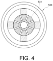
- FIG. 4 is bottom view of a portion of the spray pump according to another embodiment of the present disclosure.
- FIG. 1 is a cross-sectional view of a spray pump according to one embodiment of the present disclosure
- FIG. 2 is an enlarged view of part A of the spray pump illustrated in FIG. 1 .
- a spray pump of an embodiment of the present disclosure includes a syringe 100 , a valve member 200 , a valve rod 300 and an operation member 400 .
- the spray pump of this embodiment is a device for discharging a viscous liquid L and spraying the discharged viscous liquid L for application.
- the viscous liquid L is a generic term for an insulating and non-insulating resin having a viscosity, such as a highly viscous conductive liquid for forming an electromagnetic wave shielding film of a semiconductor chip package.
- the syringe 100 is formed in a shape of a container so that the viscous liquid L may be stored.
- the valve member 200 includes a reservoir 211 , a nozzle 221 and a sheath passage 231 .
- the reservoir 211 stores the viscous liquid L supplied from the syringe 100 .
- the nozzle 221 is connected to a lower portion of the reservoir 211 so as to discharge the viscous liquid L stored in the reservoir 211 to an outside.
- the sheath passage 231 is formed to extend toward an end of the nozzle 221 .
- a pressurized gas is discharged through sheath passage 231 to spray the viscous liquid L discharged from the nozzle 221 .
- the valve member 200 includes a valve body 210 , a nozzle member 220 and a nozzle cover member 230 .
- the reservoir 211 of the valve member 200 is formed on the valve body 210 .
- the reservoir 211 is a space in which the viscous liquid L supplied from the syringe 100 is stored.
- the reservoir 211 is formed so that a circular cross-section inside the valve body 210 extends in a longitudinal direction.
- the nozzle member 220 is installed in a lower portion of the valve body 210 .
- the nozzle 221 is formed on the nozzle member 220 .
- the nozzle member 220 is formed so that an outer diameter decreases along the extending direction of the nozzle 221 .
- the nozzle 221 is connected to the lower portion of the reservoir 211 to discharge the viscous liquid L of the reservoir 211 to the outside.
- An inner diameter of the nozzle 221 may be variously changed according to types and uses of the viscous liquid L and processes in which the viscous liquid L is used.
- the nozzle member 220 may be formed separately from the valve body 210 and then coupled to the valve body 210 as illustrated in FIG. 2 , but may also be formed integrally with the valve body 210 .
- the nozzle cover member 230 is coupled to the nozzle member 220 or the valve body 210 so as to cover a part or all of an outer surface of the nozzle member 220 .
- the sheath passage 231 is formed to extend through the nozzle cover member 230 between an inner surface of the nozzle cover member 230 and an outer surface of the nozzle member 220 .
- a pipe is connected to the sheath passage 231 to deliver a pressurized air supplied from an outside to the sheath passage 231 .
- the sheath passage 231 between the nozzle cover member 230 and the nozzle member 220 is formed to be closer to the nozzle 221 as it progresses along a direction in which the nozzle 221 extends. That is, a portion of the sheath passage 231 is formed to be inclined with respect to the extending direction of the nozzle 221 .
- the nozzle cover member 230 is formed such that an inner diameter decreases along the extending direction of the nozzle 221 .
- an end of the sheath passage 231 is disposed in front (i.e., below) than an end of the nozzle 221 .
- a position of the nozzle cover member 230 with respect to the valve body 210 is fixed by a fixing bolt 232 .
- the position of the nozzle cover member 230 may be fixed by fixing bolt 232 .
- a gap between the nozzle cover member 230 and the nozzle member 220 may be adjusted.
- a flow rate of the gas injected through the sheath passage 231 may be adjusted.
- a position where the gas injected from the sheath passage 231 meets the viscous liquid L discharged from the nozzle 221 may also be adjusted.
- the nozzle cover member 230 may be formed to be screwed to the valve body 210 . That is, by tightening or loosening the nozzle cover member 230 with respect to the valve body 210 , after a height of the nozzle cover member 230 with respect to the valve body 210 is adjusted, the height may be fixed by the fixing bolt 232 .
- Such the nozzle cover member may be designed and changed in various structures and shapes according to uses and purposes, and may be replaced with a cover member having a different structure as necessary.
- the valve rod 300 is formed to extend in a longitudinal direction and is inserted into the reservoir 211 of the valve body 210 .
- the valve rod 300 is moved forward and backward along the extension direction of the reservoir 211 by the operation member 400 .
- the valve rod 300 is lifted up and down by the operation member 400 .
- the viscous liquid L stored in the reservoir 211 of the valve body 210 is discharged to the outside through the nozzle 221 .
- the valve rod 300 includes a needle 310 and a valve guide 320 .
- the needle 310 is formed at an end of the valve rod 300 .
- the needle 310 of the valve rod 300 faces the nozzle 221 .
- a moment generated by the movement of the valve rod 300 is transferred to the viscous liquid L, so that the viscous liquid L is discharged through the nozzle 221 .
- an outer diameter of the needle 310 decreases, an amount of the viscous liquid L discharged through the nozzle 221 decreases.
- the amount of viscous liquid L discharged through the nozzle 221 increases.
- a reservoir guide 212 and a guide flow passage 213 are formed in the valve body 210 .
- the reservoir guide 212 is formed in the reservoir 211 of the valve body 210 .
- the reservoir guide 212 is formed in a form of a groove formed on an inner wall of the reservoir 211 .
- the reservoir guide 212 extends along a forward/backward direction (vertical direction in the present embodiments) of the valve rod 300 .
- the reservoir guide 212 is disposed in the lower portion of the reservoir 211 adjacent to the nozzle 221 in the valve body 210 .
- a shape of the reservoir guide 212 may be variously modified, but in the present embodiment, as illustrated in FIG.
- a cross-section is formed in a cross shape (+) and extends vertically.
- the reservoir guide 212 guides the forward and backward movement of the valve rod 300 .
- the guide flow passage 213 provides a path through which the viscous liquid L stored in the reservoir 211 is smoothly supplied toward the nozzle 221 . That is, the guide flow passage 213 of the valve body 210 connects a front space and a rear space of the reservoir guide 212 so that the viscous liquid L flows smoothly between the front space and the rear space of the reservoir guide 212 .
- the front space of the reservoir guide 212 means a portion close to the nozzle 221 of the valve body 210 in the reservoir 211
- the rear space means a portion farther from the nozzle 221 of the valve body 210 in the reservoir 211 .
- the valve guide 320 of the valve rod 300 is formed at a position corresponding to the reservoir guide 212 of the reservoir 211 in an outer surface of the valve rod 300 .
- the valve guide 320 is disposed behind the needle 310 and is formed to protrude from the outer surface of the valve rod 300 .
- the valve guide 320 is formed in a shape corresponding to the reservoir guide 212 so as to be inserted into the reservoir guide 212 .
- the cross-section of the reservoir guide 212 is formed in a cross shape (+), and the cross-section of the valve guide 320 is also formed in a cross shape (+) as illustrated in FIG. 3 .
- valve guide 320 formed on the valve rod 300 is inserted into the reservoir guide 212 and slides forward and backward while linear movement is guided by the reservoir guide 212 .
- An outer diameter of the valve guide 320 is larger than the outer diameter of the needle 310 .
- the operation member 400 moves the valve rod 300 forward and backward with respect to the valve body 210 as described above.
- the operation member 400 may be composed of various actuators that may linearly move the valve rod 300 .
- the operation member 400 is formed as an actuator composed of a piezoelectric element whose length varies according to an applied voltage.
- the operation member 400 is formed of a multi-stack type piezoelectric actuators 410 and 420 in which a plurality of piezoelectric elements are stacked.
- the piezoelectric actuators 410 and 420 are disposed at positions capable of contacting one end of a lever 440 rotatably installed with respect to a hinge axis 430 .
- An opposite end of the lever 440 is coupled with the valve rod 300 .
- the hinge axis 430 is disposed close to the piezoelectric actuators 410 and 420 .
- the lever 440 is rotated, and accordingly, the valve rod 300 is moved forward and backward with respect to the valve body 210 .
- the operation member 400 moves the valve rod 300 forward and backward quickly, the viscous liquid L is discharged by the needle 310 and the nozzle 221 .
- the viscous liquid L stored in the syringe 100 is supplied to the reservoir 211 .
- a pneumatic regulator (not illustrated) for pushing the viscous liquid L to the reservoir 211 with a constant pressure is connected to the syringe 100 .
- the viscous liquid L delivered from the syringe 100 is temporarily stored in the reservoir 211 .
- the operation member 400 rapidly elevates the valve rod 300 inserted into the reservoir 211 to discharge the viscous liquid L stored in the reservoir 211 through the nozzle 221 .
- the operation member 400 for elevating the valve rod 300 may be variously configured, but in this embodiment, the operation member 400 having the structure as illustrated in FIG. 1 is used.
- the two piezoelectric actuators 410 and 420 constituting the operation member 400 When voltage is applied to the two piezoelectric actuators 410 and 420 constituting the operation member 400 , the two piezoelectric actuators 410 and 420 alternately stretch and contract, and the lever 440 rotates clockwise or counterclockwise with respect to the hinge axis 430 . According to the rotation of the lever 440 , the valve rod 300 moves forward and backward with respect to the valve body 210 . When the lever 440 rotates clockwise, the valve rod 300 moves forward, and when the lever 440 rotates counterclockwise, the valve rod 300 moves backward.
- the hinge axis 430 of lever 440 is located closer to the piezoelectric actuators 410 and 420 than to the valve rod 300 . Therefore, an operating displacement of the piezoelectric actuators 410 and 420 is extended and transmitted to the valve rod 300 by the lever 440 . For this reason, the valve rod 300 is raised and lowered within a sufficient height range.
- the valve member 200 and the valve rod 300 of the spray pump discharge the viscous liquid L by a method of jetting pump.
- the operation member 400 moves the valve rod 300 forward and backward at high speed.
- the needle 310 of the valve rod 300 is advanced to a position adjacent to the nozzle 221 of the valve body 210 .
- the viscous liquid L is discharged through the nozzle 221 when the valve rod 300 advances so that the needle 310 advances to the position adjacent to the nozzle 221 of the valve body 210 .
- Discharge of the viscous liquid L stops when the valve rod 300 moves backward.
- the viscous liquid L stored in the nozzle 221 is discharged when the valve rod 300 moves forward again.
- This jetting pump method may discharge a minute amount of the viscous liquid L very accurately and quickly.
- a shaking of a lower end of the valve rod 300 is suppressed through the reservoir guide 212 formed in the reservoir 211 and the valve guide 320 protruding from the valve rod 300 and inserted into the reservoir guide 212 .
- the end portion of the valve rod 300 is prevented from shaking by an interaction between the valve guide 320 and the reservoir guide 212 and moves in a designated path. That is, the valve guide 320 is guided by the reservoir guide 212 while being inserted into the reservoir guide 212 to slide back and forth.
- an opposite end portion (that is, a portion adjacent to the needle 310 ) of the valve rod 300 connected to the operation member 400 is not fixed with respect to other configurations, but quickly moves forward and backward in the designated path by the interaction of the reservoir guide 212 and the valve guide 320 without shaking.
- the reservoir guide 212 supports the valve guide 320 so that the valve guide 320 moves up and down without being shaken laterally.
- the reservoir guide 212 is formed below the reservoir 211 , and the valve guide 320 is also formed at the position corresponding to the reservoir guide 212 .
- This point is a point where a lateral deformation of the valve rod 300 according to the shaking of the valve rod 300 may occur the most, but the reservoir guide 212 supports the valve guide 320 to slide without shaking in the lateral direction, so that no bending of the valve rod 300 occurs.
- it is preferable that a gap between the valve guide 320 and the reservoir guide 212 is formed as small as possible so that shaking due to vibration of the valve rod 300 may be minimized.
- the spray pump according to this embodiment includes a guide flow passage 213 so that the viscous liquid L is smoothly supplied to the nozzle 221 in the reservoir 211 .
- the guide flow passage 213 is formed on the valve body 210 to connect the front space and the rear space of the reservoir guide 212 .
- the viscous liquid L stored in the rear space of the reservoir guide 212 is moved along the guide flow passage 213 to the front space (i.e., the space adjacent to the nozzle 221 ) of the reservoir guide 212 . Accordingly, the viscous liquid L may be smoothly supplied to the nozzle 221 in the reservoir 211 by the guide flow passage 213 .
- a high-pressure gas for spraying the viscous liquid L is supplied to the sheath passage 231 from a pneumatic regulator (not illustrated) connected by the pipe.
- a pneumatic regulator not illustrated
- the sheath passage 231 is inclined along a extending direction of the nozzle 221 , the pressurized gas flowing into the sheath passage 231 is concentrated toward the nozzle 221 and is pressurized and discharged.
- the gas supplied to the sheath passage 231 is injected at a faster speed as it approaches the nozzle 221 .
- the gas of the sheath passage 231 whose pressure and speed have been increased in this way, collides with the viscous liquid L discharged from the nozzle 221 and effectively sprays the viscous liquid L.
- the pressurized gas injected into the sheath passage 231 guides the viscous liquid L sprayed from the nozzle 221 to be focused and sprayed downward at high density.
- the gap between the nozzle cover member 230 and the nozzle member 220 may be adjusted by the fixing bolt 232 .
- the flow rate of the gas injected from the sheath passage 231 may be adjusted, and the collision position and direction of the injected gas and the discharged viscous liquid L may be adjusted.
- spray characteristics of the viscous liquid L sprayed and discharged by the spray pump according to the present embodiment may be adjusted.
- a highly viscous liquid L is also effectively sprayed, and the viscous liquid L may be coated at a correct position with an accurate quantity and a desired fine line width. Since a coating surface of the viscous liquid L is implemented with a certain thickness and precise line width, a high-quality electromagnetic wave shielding film process may be performed even for a small semiconductor chip or package.
- the highly viscous liquid L discharged in the process of discharging the viscous liquid L collides with the high-pressure gas injected through the sheath passage 231 and is sprayed, so that a wide coating surface may be easily formed.
- the viscous liquid L may be discharged in an unsprayed state. Therefore, the viscous liquid L may be applied by selecting whether to spray viscous liquid L as needed. Accordingly, with a single device, a relatively high capacity viscous liquid L may be applied in a predetermined pattern without spraying the viscous liquid L, or the viscous liquid L may be sprayed and applied to a small area with a low volume.
- the operation member 400 has been described as using the piezoelectric actuators 410 and 420 composed of the piezoelectric element, but various devices that may linearly move the valve rod 300 may be used as the operation member.
- a device such as a voice coil motor, a servo motor, or a pneumatic actuator may be applied.
- the piezoelectric actuators 410 and 420 move the valve rod 300 forward and backward through the lever 440 rotatably installed on the hinge axis 430 in order to amplify a deformation amount of the piezoelectric actuators 410 and 420 , but a connection relationship between the piezoelectric actuator and the valve rod may be changed in various ways.
- the cross-sections of the reservoir guide 212 and the valve guide 320 have been described above as being formed in a cross shape (+), but the cross-sections of the reservoir guide and the valve guide may be variously changed.
- the cross-section of the reservoir guide may be formed in a circular shape
- the cross-section of the valve guide may be formed in a circular shape corresponding to the reservoir guide.
- the cross-section of the reservoir guide may be formed in a non-circular shape like an ellipse, and the cross-section of the valve guide may be formed in a shape corresponding to the reservoir guide.
- the cross section of the reservoir guide may be formed in a polygonal shape, and the cross section of the valve guide may be formed in a polygonal shape corresponding to the reservoir guide.
- the reservoir guide is formed in a shape extending in the reservoir, and the valve guide may be variously changed to have a shape in which movement may be restricted by the reservoir guide.
- the guide flow passage 213 is a passage formed separately in the valve body 210
- a spray pump having a structure in which a part of the reservoir guide functions as the guide flow passage or the reservoir guide is not formed may be configured.
- the reservoir guide is configured in a cross shape as described above and the valve guide is configured in a shape similar to a flat screw driver
- the viscous liquid L may flow through a groove into which the valve guide is not inserted.
- a spray pump of various structures in which the reservoir guide slides and supports the valve guide while allowing a flow path through which the viscous liquid L may flow between the reservoir guide and the valve guide may be configured.
- a spray pump having a structure that does not include the reservoir guide 212 , the valve guide 320 , the guide flow passage 213 , and the like may be configured.
- the sheath passage 231 was connected between the inner surface of the nozzle cover member 230 and the outer surface of the nozzle member 220 .
- a groove may be formed only on the inner surface of the nozzle cover member so that the sheath passage is formed between the nozzle cover member and the nozzle member, or a groove may be formed only on the outer surface of the nozzle member so that the sheath passage is formed between the nozzle cover member and the nozzle member.
- the sheath passage may extend along the interior of the nozzle cover member so as to be formed only on the interior of the nozzle cover member.
- a portion of the sheath passage may be formed in the nozzle member, and a remaining portion of the sheath passage may be formed in the nozzle cover member. That is, the beginning of the sheath passage may be formed in any one of the nozzle member and the nozzle cover member, and the end of the sheath passage may be formed in the other one of the nozzle member and the nozzle cover member.
- the sheath passage 231 of the above-described embodiment has been described as being formed in a ring shape inclined along the circumferential direction of the nozzle member 220 , but the sheath passage may be formed in a radially extending structure as illustrated in FIG. 4 . That is, the sheath passage may be formed of a plurality of straight sheath division passages 531 in a nozzle cover member 530 . The plurality of straight sheath division passages 531 extend radially about the center of the nozzle 221 and arranged along the circumferential direction. The number, arrangement distance and shape of the sheath division passages 531 may be variously modified.
- the spray pump of the present disclosure may micro-discharge the viscous liquid ranging from low to high viscosity in a quantitative manner.
- the spray pump of the present disclosure may miniaturize devices capable of atomizing liquids by spraying.
- the spray pump of the present disclosure may shorten a spraying path to prevent changes in liquid properties and keep spraying quality constant.
Landscapes
- Nozzles (AREA)
- Physics & Mathematics (AREA)
- Health & Medical Sciences (AREA)
- Electromagnetism (AREA)
- Toxicology (AREA)
- Coating Apparatus (AREA)
Abstract
Description
- This application is based on and claims priority under 35 U.S.C. § 119 to Korean Patent Application No. 10-2021-0191187, filed on Dec. 29, 2021, in the Korean Intellectual Property Office, the disclosure of which is incorporated by reference herein in its entirety.
- The present disclosure relates to a spray pump, and more particularly, to a spray pump capable of spraying and applying a viscous liquid.
- As the scope of application of semiconductors such as electronic products and devices, automobile industries, and military industries has been expanded, the demand for semiconductors is gradually increasing. In the case of a semiconductor package, an electromagnetic wave shielding film is generally formed in order to prevent electromagnetic wave emission or damage to an internal circuit due to external electromagnetic waves and to ensure stable operation of devices.
- As electronic products are manufactured in a thin and small form, the demand for packaging is rapidly increasing. Electromagnetic wave shielding has a greater impact on systems or components that are smaller than wavelength. With classical shielding methods, it is difficult to shield electromagnetic waves of miniaturized and lightweight electronic products.
- A sputtering (deposition) process is sometimes used as a method of forming electromagnetic wave shielding films. In the case of the method using the sputtering process, the process is complicated, and it takes a lot of time and money. In addition, there are inconveniences in the process such as masking where electromagnetic wave shielding is not required. In addition, elements inside the semiconductor package may be damaged by heat generated during the sputtering process.
- Accordingly, a method of forming electromagnetic wave shielding films by applying a viscous liquid to semiconductor chips or semiconductor package using a pump capable of applying the viscous liquid without using a deposition method has been attempted. If the viscous liquid may be applied with a fine line width and accurate capacity at a correct position by using the pump that applies the viscous liquid, the productivity of the process of forming the shielding film may be improved.
- An object of the present disclosure is to provide a spray pump that may precisely apply a viscous liquid with a fine line width by spraying the viscous liquid.
- Additional aspects will be set forth in part in the description which follows and, in part, will be apparent from the description, or may be learned by practice of the presented embodiments of the disclosure.
- A spray pump in the present disclosure includes a syringe in which a viscous liquid is stored; a valve member including a reservoir receiving the viscous liquid from the syringe and storing the same, a nozzle connected to a lower portion of the reservoir to discharge the viscous liquid to an outside, and a sheath passage extending toward an end of the nozzle to eject a gas to spray the viscous liquid discharged from the nozzle; a valve rod inserted into the reservoir of the valve member so as to move forward and backward with respect to the nozzle of the valve member and discharge the viscous liquid stored in the reservoir through the nozzle; and an operation member moving the valve rod back and forth with respect to the valve member.
- The above and other aspects, features, and advantages of certain embodiments of the disclosure will be more apparent from the following description taken in conjunction with the accompanying drawings, in which:
-
FIG. 1 is a cross-sectional view of a spray pump according to one embodiment of the present disclosure; -
FIG. 2 is an enlarged view of part A of the spray pump illustrated inFIG. 1 ; -
FIG. 3 is a bottom view of a portion of the spray pump illustrated inFIG. 1 ; and -
FIG. 4 is bottom view of a portion of the spray pump according to another embodiment of the present disclosure. - Reference will now be made in detail to embodiments, examples of which are illustrated in the accompanying drawings, wherein like reference numerals refer to like elements throughout. In this regard, the present embodiments may have different forms and should not be construed as being limited to the descriptions set forth herein. Accordingly, the embodiments are merely described below, by referring to the figures, to explain aspects. As used herein, the term “and/or” includes any and all combinations of one or more of the associated listed items. Expressions such as “at least one of,” when preceding a list of elements, modify the entire list of elements and do not modify the individual elements of the list.
- Hereinafter, with reference to the accompanying drawings, a spray pump according to an embodiment of the present disclosure will be described.
-
FIG. 1 is a cross-sectional view of a spray pump according to one embodiment of the present disclosure, andFIG. 2 is an enlarged view of part A of the spray pump illustrated inFIG. 1 . - Referring to
FIGS. 1 and 2 , a spray pump of an embodiment of the present disclosure includes asyringe 100, avalve member 200, avalve rod 300 and anoperation member 400. The spray pump of this embodiment is a device for discharging a viscous liquid L and spraying the discharged viscous liquid L for application. Here, the viscous liquid L is a generic term for an insulating and non-insulating resin having a viscosity, such as a highly viscous conductive liquid for forming an electromagnetic wave shielding film of a semiconductor chip package. - The
syringe 100 is formed in a shape of a container so that the viscous liquid L may be stored. - The
valve member 200 includes areservoir 211, anozzle 221 and asheath passage 231. Thereservoir 211 stores the viscous liquid L supplied from thesyringe 100. Thenozzle 221 is connected to a lower portion of thereservoir 211 so as to discharge the viscous liquid L stored in thereservoir 211 to an outside. Thesheath passage 231 is formed to extend toward an end of thenozzle 221. A pressurized gas is discharged throughsheath passage 231 to spray the viscous liquid L discharged from thenozzle 221. - In this embodiment, the
valve member 200 includes avalve body 210, anozzle member 220 and anozzle cover member 230. - The
reservoir 211 of thevalve member 200 is formed on thevalve body 210. Thereservoir 211 is a space in which the viscous liquid L supplied from thesyringe 100 is stored. In the case of this embodiment, thereservoir 211 is formed so that a circular cross-section inside thevalve body 210 extends in a longitudinal direction. - The
nozzle member 220 is installed in a lower portion of thevalve body 210. Thenozzle 221 is formed on thenozzle member 220. Thenozzle member 220 is formed so that an outer diameter decreases along the extending direction of thenozzle 221. Thenozzle 221 is connected to the lower portion of thereservoir 211 to discharge the viscous liquid L of thereservoir 211 to the outside. An inner diameter of thenozzle 221 may be variously changed according to types and uses of the viscous liquid L and processes in which the viscous liquid L is used. Thenozzle member 220 may be formed separately from thevalve body 210 and then coupled to thevalve body 210 as illustrated inFIG. 2 , but may also be formed integrally with thevalve body 210. - The
nozzle cover member 230 is coupled to thenozzle member 220 or thevalve body 210 so as to cover a part or all of an outer surface of thenozzle member 220. - The
sheath passage 231 is formed to extend through thenozzle cover member 230 between an inner surface of thenozzle cover member 230 and an outer surface of thenozzle member 220. A pipe is connected to thesheath passage 231 to deliver a pressurized air supplied from an outside to thesheath passage 231. Thesheath passage 231 between thenozzle cover member 230 and thenozzle member 220 is formed to be closer to thenozzle 221 as it progresses along a direction in which thenozzle 221 extends. That is, a portion of thesheath passage 231 is formed to be inclined with respect to the extending direction of thenozzle 221. To this end, thenozzle cover member 230 is formed such that an inner diameter decreases along the extending direction of thenozzle 221. In addition, it is preferable that an end of thesheath passage 231 is disposed in front (i.e., below) than an end of thenozzle 221. - A position of the
nozzle cover member 230 with respect to thevalve body 210 is fixed by afixing bolt 232. After the position of thenozzle cover member 230 with respect to thevalve body 210 is adjusted, the position of thenozzle cover member 230 may be fixed by fixingbolt 232. In this way, a gap between thenozzle cover member 230 and thenozzle member 220 may be adjusted. By adjusting the gap between thenozzle cover member 230 and thenozzle member 220, a flow rate of the gas injected through thesheath passage 231 may be adjusted. In some cases, a position where the gas injected from thesheath passage 231 meets the viscous liquid L discharged from thenozzle 221 may also be adjusted. Thenozzle cover member 230 may be formed to be screwed to thevalve body 210. That is, by tightening or loosening thenozzle cover member 230 with respect to thevalve body 210, after a height of thenozzle cover member 230 with respect to thevalve body 210 is adjusted, the height may be fixed by the fixingbolt 232. Such the nozzle cover member may be designed and changed in various structures and shapes according to uses and purposes, and may be replaced with a cover member having a different structure as necessary. - The
valve rod 300 is formed to extend in a longitudinal direction and is inserted into thereservoir 211 of thevalve body 210. Thevalve rod 300 is moved forward and backward along the extension direction of thereservoir 211 by theoperation member 400. In the case of this embodiment, as illustrated inFIGS. 1 and 2 , thevalve rod 300 is lifted up and down by theoperation member 400. As such, when thevalve rod 300 repeats forward and backward, the viscous liquid L stored in thereservoir 211 of thevalve body 210 is discharged to the outside through thenozzle 221. - In this embodiment, the
valve rod 300 includes aneedle 310 and avalve guide 320. As illustrated inFIG. 2 , theneedle 310 is formed at an end of thevalve rod 300. Theneedle 310 of thevalve rod 300 faces thenozzle 221. A moment generated by the movement of thevalve rod 300 is transferred to the viscous liquid L, so that the viscous liquid L is discharged through thenozzle 221. As an outer diameter of theneedle 310 decreases, an amount of the viscous liquid L discharged through thenozzle 221 decreases. As the outer diameter of theneedle 310 increases, the amount of viscous liquid L discharged through thenozzle 221 increases. - Referring to
FIGS. 1 and 2 , areservoir guide 212 and aguide flow passage 213 are formed in thevalve body 210. Thereservoir guide 212 is formed in thereservoir 211 of thevalve body 210. Thereservoir guide 212 is formed in a form of a groove formed on an inner wall of thereservoir 211. Thereservoir guide 212 extends along a forward/backward direction (vertical direction in the present embodiments) of thevalve rod 300. Thereservoir guide 212 is disposed in the lower portion of thereservoir 211 adjacent to thenozzle 221 in thevalve body 210. A shape of thereservoir guide 212 may be variously modified, but in the present embodiment, as illustrated inFIG. 3 , a cross-section is formed in a cross shape (+) and extends vertically. Thereservoir guide 212 guides the forward and backward movement of thevalve rod 300. Theguide flow passage 213 provides a path through which the viscous liquid L stored in thereservoir 211 is smoothly supplied toward thenozzle 221. That is, theguide flow passage 213 of thevalve body 210 connects a front space and a rear space of thereservoir guide 212 so that the viscous liquid L flows smoothly between the front space and the rear space of thereservoir guide 212. The front space of thereservoir guide 212 means a portion close to thenozzle 221 of thevalve body 210 in thereservoir 211, and the rear space means a portion farther from thenozzle 221 of thevalve body 210 in thereservoir 211. - The
valve guide 320 of thevalve rod 300 is formed at a position corresponding to thereservoir guide 212 of thereservoir 211 in an outer surface of thevalve rod 300. Thevalve guide 320 is disposed behind theneedle 310 and is formed to protrude from the outer surface of thevalve rod 300. Thevalve guide 320 is formed in a shape corresponding to thereservoir guide 212 so as to be inserted into thereservoir guide 212. As described above, the cross-section of thereservoir guide 212 is formed in a cross shape (+), and the cross-section of thevalve guide 320 is also formed in a cross shape (+) as illustrated inFIG. 3 . When thevalve rod 300 moves forward and backward within thereservoir 211 of thevalve body 210, thevalve guide 320 formed on thevalve rod 300 is inserted into thereservoir guide 212 and slides forward and backward while linear movement is guided by thereservoir guide 212. An outer diameter of thevalve guide 320 is larger than the outer diameter of theneedle 310. - The
operation member 400 moves thevalve rod 300 forward and backward with respect to thevalve body 210 as described above. Theoperation member 400 may be composed of various actuators that may linearly move thevalve rod 300. In this embodiment, theoperation member 400 is formed as an actuator composed of a piezoelectric element whose length varies according to an applied voltage. - In this embodiment, the
operation member 400 is formed of a multi-stacktype piezoelectric actuators piezoelectric actuators lever 440 rotatably installed with respect to ahinge axis 430. An opposite end of thelever 440 is coupled with thevalve rod 300. At this time, thehinge axis 430 is disposed close to thepiezoelectric actuators piezoelectric actuators lever 440 is rotated, and accordingly, thevalve rod 300 is moved forward and backward with respect to thevalve body 210. As such, when theoperation member 400 moves thevalve rod 300 forward and backward quickly, the viscous liquid L is discharged by theneedle 310 and thenozzle 221. - Hereinafter, an operation of the spray pump according to an embodiment configured as described above will be described.
- The viscous liquid L stored in the
syringe 100 is supplied to thereservoir 211. A pneumatic regulator (not illustrated) for pushing the viscous liquid L to thereservoir 211 with a constant pressure is connected to thesyringe 100. The viscous liquid L delivered from thesyringe 100 is temporarily stored in thereservoir 211. - The
operation member 400 rapidly elevates thevalve rod 300 inserted into thereservoir 211 to discharge the viscous liquid L stored in thereservoir 211 through thenozzle 221. Theoperation member 400 for elevating thevalve rod 300 may be variously configured, but in this embodiment, theoperation member 400 having the structure as illustrated inFIG. 1 is used. - When voltage is applied to the two
piezoelectric actuators operation member 400, the twopiezoelectric actuators lever 440 rotates clockwise or counterclockwise with respect to thehinge axis 430. According to the rotation of thelever 440, thevalve rod 300 moves forward and backward with respect to thevalve body 210. When thelever 440 rotates clockwise, thevalve rod 300 moves forward, and when thelever 440 rotates counterclockwise, thevalve rod 300 moves backward. Thehinge axis 430 oflever 440 is located closer to thepiezoelectric actuators valve rod 300. Therefore, an operating displacement of thepiezoelectric actuators valve rod 300 by thelever 440. For this reason, thevalve rod 300 is raised and lowered within a sufficient height range. - The
valve member 200 and thevalve rod 300 of the spray pump according to this embodiment discharge the viscous liquid L by a method of jetting pump. Theoperation member 400 moves thevalve rod 300 forward and backward at high speed. When thevalve rod 300 is advanced, theneedle 310 of thevalve rod 300 is advanced to a position adjacent to thenozzle 221 of thevalve body 210. The viscous liquid L is discharged through thenozzle 221 when thevalve rod 300 advances so that theneedle 310 advances to the position adjacent to thenozzle 221 of thevalve body 210. Discharge of the viscous liquid L stops when thevalve rod 300 moves backward. The viscous liquid L stored in thenozzle 221 is discharged when thevalve rod 300 moves forward again. This jetting pump method may discharge a minute amount of the viscous liquid L very accurately and quickly. - In the case of the spray pump of this embodiment, a shaking of a lower end of the
valve rod 300 is suppressed through thereservoir guide 212 formed in thereservoir 211 and thevalve guide 320 protruding from thevalve rod 300 and inserted into thereservoir guide 212. Specifically, when thevalve rod 300 is moved forward and backward by theoperation member 400, the end portion of thevalve rod 300 is prevented from shaking by an interaction between thevalve guide 320 and thereservoir guide 212 and moves in a designated path. That is, thevalve guide 320 is guided by thereservoir guide 212 while being inserted into thereservoir guide 212 to slide back and forth. Therefore, an opposite end portion (that is, a portion adjacent to the needle 310) of thevalve rod 300 connected to theoperation member 400 is not fixed with respect to other configurations, but quickly moves forward and backward in the designated path by the interaction of thereservoir guide 212 and thevalve guide 320 without shaking. Thereservoir guide 212 supports thevalve guide 320 so that thevalve guide 320 moves up and down without being shaken laterally. - As described above, the
reservoir guide 212 is formed below thereservoir 211, and thevalve guide 320 is also formed at the position corresponding to thereservoir guide 212. This point is a point where a lateral deformation of thevalve rod 300 according to the shaking of thevalve rod 300 may occur the most, but thereservoir guide 212 supports thevalve guide 320 to slide without shaking in the lateral direction, so that no bending of thevalve rod 300 occurs. In addition, it is preferable that a gap between thevalve guide 320 and thereservoir guide 212 is formed as small as possible so that shaking due to vibration of thevalve rod 300 may be minimized. - In addition, as described above, since the gap between the
valve guide 320 and thereservoir guide 212 is small, it may be difficult to sufficiently supply the viscous liquid L to a space between thevalve guide 320 and thereservoir guide 212 in some cases. In this case, the spray pump according to this embodiment includes aguide flow passage 213 so that the viscous liquid L is smoothly supplied to thenozzle 221 in thereservoir 211. Theguide flow passage 213 is formed on thevalve body 210 to connect the front space and the rear space of thereservoir guide 212. The viscous liquid L stored in the rear space of thereservoir guide 212 is moved along theguide flow passage 213 to the front space (i.e., the space adjacent to the nozzle 221) of thereservoir guide 212. Accordingly, the viscous liquid L may be smoothly supplied to thenozzle 221 in thereservoir 211 by theguide flow passage 213. - As described above, when the viscous liquid L is discharged from the
nozzle 221 by a jetting way, a high-pressure gas for spraying the viscous liquid L is supplied to thesheath passage 231 from a pneumatic regulator (not illustrated) connected by the pipe. As described above, since thesheath passage 231 is inclined along a extending direction of thenozzle 221, the pressurized gas flowing into thesheath passage 231 is concentrated toward thenozzle 221 and is pressurized and discharged. That is, due to the shape of thesheath passage 231 in which the cross-section area gradually decreases along the extending direction of thenozzle 221, the gas supplied to thesheath passage 231 is injected at a faster speed as it approaches thenozzle 221. The gas of thesheath passage 231, whose pressure and speed have been increased in this way, collides with the viscous liquid L discharged from thenozzle 221 and effectively sprays the viscous liquid L. On the other hand, as the end of thesheath passage 231 is formed lower than the end of thenozzle 221, the pressurized gas injected into thesheath passage 231 guides the viscous liquid L sprayed from thenozzle 221 to be focused and sprayed downward at high density. - The gap between the
nozzle cover member 230 and thenozzle member 220 may be adjusted by the fixingbolt 232. By adjusting the gap between thenozzle cover member 230 and thenozzle member 220, the flow rate of the gas injected from thesheath passage 231 may be adjusted, and the collision position and direction of the injected gas and the discharged viscous liquid L may be adjusted. Through this, spray characteristics of the viscous liquid L sprayed and discharged by the spray pump according to the present embodiment may be adjusted. - As described above, by using the spray pump according to the present disclosure, a highly viscous liquid L is also effectively sprayed, and the viscous liquid L may be coated at a correct position with an accurate quantity and a desired fine line width. Since a coating surface of the viscous liquid L is implemented with a certain thickness and precise line width, a high-quality electromagnetic wave shielding film process may be performed even for a small semiconductor chip or package.
- In addition, the highly viscous liquid L discharged in the process of discharging the viscous liquid L collides with the high-pressure gas injected through the
sheath passage 231 and is sprayed, so that a wide coating surface may be easily formed. - In addition, when the pressurized air is not discharged through the
sheath passage 231, the viscous liquid L may be discharged in an unsprayed state. Therefore, the viscous liquid L may be applied by selecting whether to spray viscous liquid L as needed. Accordingly, with a single device, a relatively high capacity viscous liquid L may be applied in a predetermined pattern without spraying the viscous liquid L, or the viscous liquid L may be sprayed and applied to a small area with a low volume. - Although a preferable example has been described above for present disclosure, the scope of present disclosure is not limited to the form described and illustrated above.
- For example, the
operation member 400 has been described as using thepiezoelectric actuators valve rod 300 may be used as the operation member. For example, a device such as a voice coil motor, a servo motor, or a pneumatic actuator may be applied. - In addition, it was previously described that the
piezoelectric actuators valve rod 300 forward and backward through thelever 440 rotatably installed on thehinge axis 430 in order to amplify a deformation amount of thepiezoelectric actuators - In addition, the cross-sections of the
reservoir guide 212 and thevalve guide 320 have been described above as being formed in a cross shape (+), but the cross-sections of the reservoir guide and the valve guide may be variously changed. For example, the cross-section of the reservoir guide may be formed in a circular shape, and the cross-section of the valve guide may be formed in a circular shape corresponding to the reservoir guide. In addition, the cross-section of the reservoir guide may be formed in a non-circular shape like an ellipse, and the cross-section of the valve guide may be formed in a shape corresponding to the reservoir guide. The cross section of the reservoir guide may be formed in a polygonal shape, and the cross section of the valve guide may be formed in a polygonal shape corresponding to the reservoir guide. In addition to the structure described and illustrated above, the reservoir guide is formed in a shape extending in the reservoir, and the valve guide may be variously changed to have a shape in which movement may be restricted by the reservoir guide. - In addition, although it has been described above that the
guide flow passage 213 is a passage formed separately in thevalve body 210, a spray pump having a structure in which a part of the reservoir guide functions as the guide flow passage or the reservoir guide is not formed may be configured. For example, when the reservoir guide is configured in a cross shape as described above and the valve guide is configured in a shape similar to a flat screw driver, the viscous liquid L may flow through a groove into which the valve guide is not inserted. In addition, a spray pump of various structures in which the reservoir guide slides and supports the valve guide while allowing a flow path through which the viscous liquid L may flow between the reservoir guide and the valve guide may be configured. - In addition, a spray pump having a structure that does not include the
reservoir guide 212, thevalve guide 320, theguide flow passage 213, and the like may be configured. - On the other hand, it was previously described that the
sheath passage 231 was connected between the inner surface of thenozzle cover member 230 and the outer surface of thenozzle member 220. However, a groove may be formed only on the inner surface of the nozzle cover member so that the sheath passage is formed between the nozzle cover member and the nozzle member, or a groove may be formed only on the outer surface of the nozzle member so that the sheath passage is formed between the nozzle cover member and the nozzle member. Also, the sheath passage may extend along the interior of the nozzle cover member so as to be formed only on the interior of the nozzle cover member. In some cases, a portion of the sheath passage may be formed in the nozzle member, and a remaining portion of the sheath passage may be formed in the nozzle cover member. That is, the beginning of the sheath passage may be formed in any one of the nozzle member and the nozzle cover member, and the end of the sheath passage may be formed in the other one of the nozzle member and the nozzle cover member. - The
sheath passage 231 of the above-described embodiment has been described as being formed in a ring shape inclined along the circumferential direction of thenozzle member 220, but the sheath passage may be formed in a radially extending structure as illustrated inFIG. 4 . That is, the sheath passage may be formed of a plurality of straightsheath division passages 531 in anozzle cover member 530. The plurality of straightsheath division passages 531 extend radially about the center of thenozzle 221 and arranged along the circumferential direction. The number, arrangement distance and shape of thesheath division passages 531 may be variously modified. - The spray pump of the present disclosure may micro-discharge the viscous liquid ranging from low to high viscosity in a quantitative manner.
- The spray pump of the present disclosure may miniaturize devices capable of atomizing liquids by spraying.
- The spray pump of the present disclosure may shorten a spraying path to prevent changes in liquid properties and keep spraying quality constant.
- It should be understood that embodiments described herein should be considered in a descriptive sense only and not for purposes of limitation. Descriptions of features or aspects within each embodiment should typically be considered as available for other similar features or aspects in other embodiments. While one or more embodiments have been described with reference to the figures, it will be understood by those of ordinary skill in the art that various changes in form and details may be made therein without departing from the spirit and scope as defined by the following claims.
Claims (17)
Applications Claiming Priority (3)
| Application Number | Priority Date | Filing Date | Title |
|---|---|---|---|
| KR20210167120 | 2021-11-29 | ||
| KR1020210191187A KR102744205B1 (en) | 2021-11-29 | 2021-12-29 | Spray Pump |
| KR10-2021-0191187 | 2021-12-29 |
Publications (1)
| Publication Number | Publication Date |
|---|---|
| US20230201848A1 true US20230201848A1 (en) | 2023-06-29 |
Family
ID=86761596
Family Applications (1)
| Application Number | Title | Priority Date | Filing Date |
|---|---|---|---|
| US17/950,103 Pending US20230201848A1 (en) | 2021-11-29 | 2022-09-22 | Spray pump |
Country Status (3)
| Country | Link |
|---|---|
| US (1) | US20230201848A1 (en) |
| KR (1) | KR102744205B1 (en) |
| CN (1) | CN116408213A (en) |
Citations (2)
| Publication number | Priority date | Publication date | Assignee | Title |
|---|---|---|---|---|
| US5447254A (en) * | 1993-11-16 | 1995-09-05 | Nordson Corporation | Fluid dispenser with shut-off drip protection |
| US8708246B2 (en) * | 2011-10-28 | 2014-04-29 | Nordson Corporation | Positive displacement dispenser and method for dispensing discrete amounts of liquid |
Family Cites Families (6)
| Publication number | Priority date | Publication date | Assignee | Title |
|---|---|---|---|---|
| JP3357285B2 (en) * | 1998-01-26 | 2002-12-16 | アネスト岩田株式会社 | Attachment for air / airless |
| JP2011502784A (en) * | 2007-11-19 | 2011-01-27 | スプレイング システムズ カンパニー | Ultrasonic spray nozzle with cone spray form |
| KR100932297B1 (en) * | 2009-08-10 | 2009-12-16 | 한국생산기술연구원 | Liquid crystal dropping device using ultrasonic wave |
| WO2017164566A1 (en) | 2016-03-24 | 2017-09-28 | 주식회사 프로텍 | Apparatus for forming electromagnetic wave shielding film for semiconductor package and method for forming electromagnetic wave shielding film for semiconductor package |
| KR101900559B1 (en) * | 2016-08-01 | 2018-09-20 | 변도영 | Spray nozzle and system for coating using the same |
| KR102208070B1 (en) * | 2019-04-30 | 2021-01-27 | 주식회사 프로텍 | Pump for Dispensing Viscous Liquid |
-
2021
- 2021-12-29 KR KR1020210191187A patent/KR102744205B1/en active Active
-
2022
- 2022-09-22 CN CN202211156511.3A patent/CN116408213A/en active Pending
- 2022-09-22 US US17/950,103 patent/US20230201848A1/en active Pending
Patent Citations (2)
| Publication number | Priority date | Publication date | Assignee | Title |
|---|---|---|---|---|
| US5447254A (en) * | 1993-11-16 | 1995-09-05 | Nordson Corporation | Fluid dispenser with shut-off drip protection |
| US8708246B2 (en) * | 2011-10-28 | 2014-04-29 | Nordson Corporation | Positive displacement dispenser and method for dispensing discrete amounts of liquid |
Non-Patent Citations (1)
| Title |
|---|
| KR 20200126636 Translation (Year: 2020) * |
Also Published As
| Publication number | Publication date |
|---|---|
| KR20230080257A (en) | 2023-06-07 |
| KR102744205B1 (en) | 2024-12-18 |
| CN116408213A (en) | 2023-07-11 |
Similar Documents
| Publication | Publication Date | Title |
|---|---|---|
| JP6983241B2 (en) | Coating equipment and related operating methods | |
| US8545931B2 (en) | Thin line conformal coating method | |
| US6270019B1 (en) | Apparatus and method for dispensing liquid material | |
| KR101940598B1 (en) | Liquid material application device and liquid material application method | |
| US20090298251A1 (en) | Normal pressure aerosol spray apparatus and method of forming a film using the same | |
| US20230201848A1 (en) | Spray pump | |
| JP2022064482A (en) | Coating material spray nozzle and control method of the same | |
| KR101899239B1 (en) | Apparatus and Method of Forming EMI Shield Layer for Semi-conductor Package | |
| US11584139B2 (en) | Printing apparatus and printing method | |
| US12138650B2 (en) | Apparatus for ejecting viscous liquid aerosol | |
| JP2020040037A (en) | Liquid droplet application equipment and liquid droplet application method | |
| KR102208070B1 (en) | Pump for Dispensing Viscous Liquid | |
| KR101930157B1 (en) | Apparatus and Method for Dispensing Viscous Liquid | |
| TW201609269A (en) | Valve seat for dispenser | |
| JPH03267164A (en) | Coating system and coating device | |
| US7644871B2 (en) | Flux spray atomization and splash control | |
| KR20060033792A (en) | Rotary atomization head painting device | |
| KR20250097744A (en) | Method for Ejecting Viscous Liquid Aerosol | |
| KR20190014646A (en) | Spray nozzle | |
| CN106345632B (en) | Robot tool and robot for dispensing anti-corrosion wax and method therefor | |
| JP5922289B2 (en) | Trace liquid discharge method and trace liquid dispenser | |
| US12427537B2 (en) | Hybrid spray pump | |
| CN101862717A (en) | Electrostatic coating method and electrostatic coating equipment | |
| JP2002542020A (en) | Electric liquid dispensing apparatus and method for dispensing viscous liquid | |
| KR101560496B1 (en) | Switch spray nozzle |
Legal Events
| Date | Code | Title | Description |
|---|---|---|---|
| AS | Assignment |
Owner name: PROTEC CO., LTD., KOREA, REPUBLIC OF Free format text: ASSIGNMENT OF ASSIGNORS INTEREST;ASSIGNORS:HONG, SEUNG MIN;CHOI, EUI KEUN;PARK, SUNG IL;AND OTHERS;REEL/FRAME:061189/0227 Effective date: 20220830 |
|
| STPP | Information on status: patent application and granting procedure in general |
Free format text: DOCKETED NEW CASE - READY FOR EXAMINATION |
|
| STPP | Information on status: patent application and granting procedure in general |
Free format text: NON FINAL ACTION MAILED |
|
| STPP | Information on status: patent application and granting procedure in general |
Free format text: RESPONSE TO NON-FINAL OFFICE ACTION ENTERED AND FORWARDED TO EXAMINER |
|
| STPP | Information on status: patent application and granting procedure in general |
Free format text: FINAL REJECTION COUNTED, NOT YET MAILED |
|
| STPP | Information on status: patent application and granting procedure in general |
Free format text: FINAL REJECTION MAILED |
|
| STPP | Information on status: patent application and granting procedure in general |
Free format text: FINAL REJECTION MAILED |
|
| STCB | Information on status: application discontinuation |
Free format text: ABANDONED -- FAILURE TO RESPOND TO AN OFFICE ACTION |