US20230150737A1 - Child-resistant container - Google Patents
Child-resistant container Download PDFInfo
- Publication number
- US20230150737A1 US20230150737A1 US17/454,084 US202117454084A US2023150737A1 US 20230150737 A1 US20230150737 A1 US 20230150737A1 US 202117454084 A US202117454084 A US 202117454084A US 2023150737 A1 US2023150737 A1 US 2023150737A1
- Authority
- US
- United States
- Prior art keywords
- inner tray
- outer sleeve
- child
- locking
- locking mechanism
- Prior art date
- Legal status (The legal status is an assumption and is not a legal conclusion. Google has not performed a legal analysis and makes no representation as to the accuracy of the status listed.)
- Abandoned
Links
- 230000007246 mechanism Effects 0.000 claims abstract description 92
- 239000000758 substrate Substances 0.000 claims description 28
- 238000000034 method Methods 0.000 claims description 16
- 239000000463 material Substances 0.000 claims description 12
- 238000003780 insertion Methods 0.000 claims description 5
- 230000037431 insertion Effects 0.000 claims description 5
- 239000002985 plastic film Substances 0.000 claims description 4
- 239000002991 molded plastic Substances 0.000 claims description 3
- 238000007789 sealing Methods 0.000 description 24
- 235000019504 cigarettes Nutrition 0.000 description 13
- 239000000047 product Substances 0.000 description 7
- 239000000853 adhesive Substances 0.000 description 6
- 230000001070 adhesive effect Effects 0.000 description 6
- 238000010276 construction Methods 0.000 description 5
- 238000004519 manufacturing process Methods 0.000 description 5
- 239000000123 paper Substances 0.000 description 5
- 231100001261 hazardous Toxicity 0.000 description 4
- 241000218236 Cannabis Species 0.000 description 3
- 239000004743 Polypropylene Substances 0.000 description 3
- 229910052782 aluminium Inorganic materials 0.000 description 3
- XAGFODPZIPBFFR-UHFFFAOYSA-N aluminium Chemical compound [Al] XAGFODPZIPBFFR-UHFFFAOYSA-N 0.000 description 3
- 230000000994 depressogenic effect Effects 0.000 description 3
- 229940079593 drug Drugs 0.000 description 3
- 239000003814 drug Substances 0.000 description 3
- 210000003811 finger Anatomy 0.000 description 3
- 229920001903 high density polyethylene Polymers 0.000 description 3
- 239000004700 high-density polyethylene Substances 0.000 description 3
- 229920001684 low density polyethylene Polymers 0.000 description 3
- 239000004702 low-density polyethylene Substances 0.000 description 3
- 238000002483 medication Methods 0.000 description 3
- 239000005020 polyethylene terephthalate Substances 0.000 description 3
- 229920000139 polyethylene terephthalate Polymers 0.000 description 3
- 229920001155 polypropylene Polymers 0.000 description 3
- 239000004793 Polystyrene Substances 0.000 description 2
- ATJFFYVFTNAWJD-UHFFFAOYSA-N Tin Chemical compound [Sn] ATJFFYVFTNAWJD-UHFFFAOYSA-N 0.000 description 2
- 230000008901 benefit Effects 0.000 description 2
- 238000009826 distribution Methods 0.000 description 2
- 239000007769 metal material Substances 0.000 description 2
- 229920006255 plastic film Polymers 0.000 description 2
- -1 polyethylene terephthalate Polymers 0.000 description 2
- 229920002223 polystyrene Polymers 0.000 description 2
- 239000004800 polyvinyl chloride Substances 0.000 description 2
- 230000008569 process Effects 0.000 description 2
- 238000003860 storage Methods 0.000 description 2
- 239000000126 substance Substances 0.000 description 2
- 210000003813 thumb Anatomy 0.000 description 2
- 235000019505 tobacco product Nutrition 0.000 description 2
- 241000208125 Nicotiana Species 0.000 description 1
- 235000002637 Nicotiana tabacum Nutrition 0.000 description 1
- 239000011111 cardboard Substances 0.000 description 1
- 239000007795 chemical reaction product Substances 0.000 description 1
- 238000011109 contamination Methods 0.000 description 1
- 230000000881 depressing effect Effects 0.000 description 1
- 239000011888 foil Substances 0.000 description 1
- 239000012535 impurity Substances 0.000 description 1
- 229910052751 metal Inorganic materials 0.000 description 1
- 239000002184 metal Substances 0.000 description 1
- 238000012986 modification Methods 0.000 description 1
- 230000004048 modification Effects 0.000 description 1
- 238000004806 packaging method and process Methods 0.000 description 1
- 238000012856 packing Methods 0.000 description 1
- 239000011087 paperboard Substances 0.000 description 1
- 229920003023 plastic Polymers 0.000 description 1
- 239000004033 plastic Substances 0.000 description 1
- 229920000915 polyvinyl chloride Polymers 0.000 description 1
- 238000003825 pressing Methods 0.000 description 1
- 231100000331 toxic Toxicity 0.000 description 1
- 230000002588 toxic effect Effects 0.000 description 1
Images


Classifications
-
- B—PERFORMING OPERATIONS; TRANSPORTING
- B65—CONVEYING; PACKING; STORING; HANDLING THIN OR FILAMENTARY MATERIAL
- B65D—CONTAINERS FOR STORAGE OR TRANSPORT OF ARTICLES OR MATERIALS, e.g. BAGS, BARRELS, BOTTLES, BOXES, CANS, CARTONS, CRATES, DRUMS, JARS, TANKS, HOPPERS, FORWARDING CONTAINERS; ACCESSORIES, CLOSURES, OR FITTINGS THEREFOR; PACKAGING ELEMENTS; PACKAGES
- B65D50/00—Closures with means for discouraging unauthorised opening or removal thereof, with or without indicating means, e.g. child-proof closures
- B65D50/02—Closures with means for discouraging unauthorised opening or removal thereof, with or without indicating means, e.g. child-proof closures openable or removable by the combination of plural actions
- B65D50/04—Closures with means for discouraging unauthorised opening or removal thereof, with or without indicating means, e.g. child-proof closures openable or removable by the combination of plural actions requiring the combination of simultaneous actions, e.g. depressing and turning, lifting and turning, maintaining a part and turning another one
- B65D50/045—Closures with means for discouraging unauthorised opening or removal thereof, with or without indicating means, e.g. child-proof closures openable or removable by the combination of plural actions requiring the combination of simultaneous actions, e.g. depressing and turning, lifting and turning, maintaining a part and turning another one where one action elastically deforms or deflects at least part of the closure, the container or an intermediate element, e.g. a ring
- B65D50/046—Closures with means for discouraging unauthorised opening or removal thereof, with or without indicating means, e.g. child-proof closures openable or removable by the combination of plural actions requiring the combination of simultaneous actions, e.g. depressing and turning, lifting and turning, maintaining a part and turning another one where one action elastically deforms or deflects at least part of the closure, the container or an intermediate element, e.g. a ring and such deformation causes the disengagement of locking means, e.g. the release of a pawl-like element from a tooth or abutment, to allow removal of the closure by simultaneous rotation
-
- B—PERFORMING OPERATIONS; TRANSPORTING
- B65—CONVEYING; PACKING; STORING; HANDLING THIN OR FILAMENTARY MATERIAL
- B65D—CONTAINERS FOR STORAGE OR TRANSPORT OF ARTICLES OR MATERIALS, e.g. BAGS, BARRELS, BOTTLES, BOXES, CANS, CARTONS, CRATES, DRUMS, JARS, TANKS, HOPPERS, FORWARDING CONTAINERS; ACCESSORIES, CLOSURES, OR FITTINGS THEREFOR; PACKAGING ELEMENTS; PACKAGES
- B65D77/00—Packages formed by enclosing articles or materials in preformed containers, e.g. boxes, cartons, sacks or bags
- B65D77/04—Articles or materials enclosed in two or more containers disposed one within another
- B65D77/0413—Articles or materials enclosed in two or more containers disposed one within another the inner and outer containers being rigid or semi-rigid and the outer container being of polygonal cross-section formed by folding or erecting one or more blanks, e.g. carton
- B65D77/0433—Articles or materials enclosed in two or more containers disposed one within another the inner and outer containers being rigid or semi-rigid and the outer container being of polygonal cross-section formed by folding or erecting one or more blanks, e.g. carton the inner container being a tray or like shallow container, not formed by folding or erecting one or more blanks
-
- A—HUMAN NECESSITIES
- A24—TOBACCO; CIGARS; CIGARETTES; SIMULATED SMOKING DEVICES; SMOKERS' REQUISITES
- A24F—SMOKERS' REQUISITES; MATCH BOXES; SIMULATED SMOKING DEVICES
- A24F15/00—Receptacles or boxes specially adapted for cigars, cigarettes, simulated smoking devices or cigarettes therefor
- A24F15/12—Receptacles or boxes specially adapted for cigars, cigarettes, simulated smoking devices or cigarettes therefor for pocket use
-
- B—PERFORMING OPERATIONS; TRANSPORTING
- B65—CONVEYING; PACKING; STORING; HANDLING THIN OR FILAMENTARY MATERIAL
- B65D—CONTAINERS FOR STORAGE OR TRANSPORT OF ARTICLES OR MATERIALS, e.g. BAGS, BARRELS, BOTTLES, BOXES, CANS, CARTONS, CRATES, DRUMS, JARS, TANKS, HOPPERS, FORWARDING CONTAINERS; ACCESSORIES, CLOSURES, OR FITTINGS THEREFOR; PACKAGING ELEMENTS; PACKAGES
- B65D5/00—Rigid or semi-rigid containers of polygonal cross-section, e.g. boxes, cartons or trays, formed by folding or erecting one or more blanks made of paper
- B65D5/38—Drawer-and-shell type containers
-
- B—PERFORMING OPERATIONS; TRANSPORTING
- B65—CONVEYING; PACKING; STORING; HANDLING THIN OR FILAMENTARY MATERIAL
- B65D—CONTAINERS FOR STORAGE OR TRANSPORT OF ARTICLES OR MATERIALS, e.g. BAGS, BARRELS, BOTTLES, BOXES, CANS, CARTONS, CRATES, DRUMS, JARS, TANKS, HOPPERS, FORWARDING CONTAINERS; ACCESSORIES, CLOSURES, OR FITTINGS THEREFOR; PACKAGING ELEMENTS; PACKAGES
- B65D5/00—Rigid or semi-rigid containers of polygonal cross-section, e.g. boxes, cartons or trays, formed by folding or erecting one or more blanks made of paper
- B65D5/42—Details of containers or of foldable or erectable container blanks
- B65D5/44—Integral, inserted or attached portions forming internal or external fittings
- B65D5/50—Internal supporting or protecting elements for contents
- B65D5/5028—Elements formed separately from the container body
- B65D5/503—Tray-like elements formed in one piece
-
- B—PERFORMING OPERATIONS; TRANSPORTING
- B65—CONVEYING; PACKING; STORING; HANDLING THIN OR FILAMENTARY MATERIAL
- B65D—CONTAINERS FOR STORAGE OR TRANSPORT OF ARTICLES OR MATERIALS, e.g. BAGS, BARRELS, BOTTLES, BOXES, CANS, CARTONS, CRATES, DRUMS, JARS, TANKS, HOPPERS, FORWARDING CONTAINERS; ACCESSORIES, CLOSURES, OR FITTINGS THEREFOR; PACKAGING ELEMENTS; PACKAGES
- B65D85/00—Containers, packaging elements or packages, specially adapted for particular articles or materials
- B65D85/07—Containers, packaging elements or packages, specially adapted for particular articles or materials for compressible or flexible articles
- B65D85/08—Containers, packaging elements or packages, specially adapted for particular articles or materials for compressible or flexible articles rod-shaped or tubular
- B65D85/10—Containers, packaging elements or packages, specially adapted for particular articles or materials for compressible or flexible articles rod-shaped or tubular for cigarettes
- B65D85/1036—Containers formed by erecting a rigid or semi-rigid blank
-
- B—PERFORMING OPERATIONS; TRANSPORTING
- B65—CONVEYING; PACKING; STORING; HANDLING THIN OR FILAMENTARY MATERIAL
- B65D—CONTAINERS FOR STORAGE OR TRANSPORT OF ARTICLES OR MATERIALS, e.g. BAGS, BARRELS, BOTTLES, BOXES, CANS, CARTONS, CRATES, DRUMS, JARS, TANKS, HOPPERS, FORWARDING CONTAINERS; ACCESSORIES, CLOSURES, OR FITTINGS THEREFOR; PACKAGING ELEMENTS; PACKAGES
- B65D2215/00—Child-proof means
- B65D2215/02—Child-proof means requiring the combination of simultaneous actions
Definitions
- Embodiments of the present disclosure relate generally to small containers and more specifically containers with child-resistant features, and related methods of use thereof.
- Portable, child-resistant containers may be useful for a variety of applications.
- such containers may be used to store medications, tobacco products, cannabis products, or other products and substances that may be hazardous to children.
- such containers may be lightweight, may be easily opened for access to the contents, may be easily closed to keep the contents fresh, and may include a mechanism suitable for preventing children from accessing the contents.
- Existing containers may lack these desirable features and may be constructed in a manner that is inefficient for mass production. Accordingly, existing containers may be unsuitable for storage of the items described and existing containers may also be unsuitable for retail distribution of various products.
- the present disclosure is directed to addressing the above-referenced challenges.
- the background description provided herein is for the purpose of generally presenting the context of the disclosure. Unless otherwise indicated herein, the materials described in this section are not prior art to the claims in this application and are not admitted to be prior art, or suggestions of the prior art, by inclusion in this section.
- child-resistant containers and methods for using the same are described.
- a child-resistant container may include: an inner tray including a first side, a second side opposite the first side, a first locking mechanism on the first side, and a second locking mechanism on the second side; and an outer sleeve including a first sleeve side, a second sleeve side opposite the first sleeve side, a first locking port on the first sleeve side, a second locking port on the second sleeve side, an open end, and one or more catches located on an interior of the outer sleeve toward the open end.
- the inner tray may be configured to be slidably inserted into the outer sleeve through the open end such that each of the locking mechanisms releasably engages at least one of the locking ports upon insertion of the inner tray into the outer sleeve; and at least one of the locking mechanisms may be further configured, upon sliding the inner tray outwardly through the open end of the outer sleeve, to engage with the one or more catches to prevent the inner tray from being fully withdrawn from the outer sleeve.
- a child-resistant container may include: an inner tray including a first side and a first locking mechanism positioned on the first side; and an outer sleeve including a first sleeve side, a first locking port on the first sleeve side, an open end, and a catch located on an interior of the outer sleeve toward the open end.
- the inner tray may be configured to be slidably inserted into the outer sleeve through the open end such that the locking mechanism releasably engages the locking port upon insertion of the inner tray into the outer sleeve; and the locking mechanism may be further configured, upon sliding the inner tray outwardly through the open end of the outer sleeve, to engage with the catch to prevent the inner tray from being fully withdrawn from the outer sleeve.
- a method of accessing contents of a child-resistant container comprising an inner tray positioned with an outer sleeve may include: disengaging a first locking mechanism of the inner tray from a first locking port of the outer sleeve and a second locking mechanism of the inner tray from a second locking port of the outer sleeve; withdrawing the tray through an open end of the outer sleeve until at least one of the first locking mechanism and the second locking mechanism engages with at least one catch positioned on an interior of the outer sleeve to prevent the inner tray from being fully withdrawn from the outer sleeve; and accessing the contents located in a cavity of the inner tray.
- FIG. 1 depicts an isometric view of a container according to some embodiments.
- FIG. 2 depicts an isometric view of a container in a partially exploded configuration according to some embodiments.
- FIG. 3 A depicts an isometric view of a tray of a container according to some embodiments.
- FIG. 3 B depicts an isometric view of a tray of a container according to some embodiments.
- FIG. 4 depicts an isometric view of a tray of a container according to some embodiments.
- FIG. 5 depicts a rear view of a tray according to some embodiments.
- FIG. 6 A depicts a top view of a tray according to some embodiments.
- FIG. 6 B depicts a bottom view of a tray according to some embodiments.
- FIG. 7 depicts an isometric view of a locking tab according to some embodiments.
- FIG. 8 A depicts a side view of a sleeve according to some embodiments.
- FIG. 8 B depicts a front view of a sleeve according to some embodiments.
- FIG. 9 depicts an isometric view of a container in an exploded configuration according to some embodiments.
- FIG. 10 depicts an isometric view of a container in an exploded configuration according to some embodiments.
- the term “based on” means “based at least in part on.”
- the singular forms “a,” “an,” and “the” include plural referents unless the context dictates otherwise.
- the term “exemplary” is used in the sense of “example” rather than “ideal.”
- the terms “comprises,” “comprising,” “includes,” “including,” or other variations thereof, are intended to cover a non-exclusive inclusion such that a process, method, or product that comprises a list of elements does not necessarily include only those elements, but may include other elements not expressly listed or inherent to such a process, method, article, or apparatus. Relative terms such as “substantially” and “generally” are used to indicate a possible variation of ⁇ 10% of a stated or understood value.
- the present disclosure is directed to improved, child-resistant containers and methods for using the same.
- the devices and methods described in the present disclosure offer significant technical benefits which will become apparent.
- Portable, child-resistant containers may be useful for storing medications, tobacco products, cannabis products, or other products and substances that may be hazardous to children.
- such containers may be used to store pre-rolled tobacco or cannabis cigarettes.
- a child-resistant container may serve multiple functions, such as protecting the contents from physical damage during shipment, maintaining the freshness of the contents before use, providing a means for a user to safely and easily transport the contents, and preventing access by children to whom the contents may be hazardous or toxic.
- Child-resistant containers may be sufficiently rigid to protect the contents, for example, during shipment to a retail location or to an end user. If the contents of a container include pre-rolled cigarettes, the container may protect the cigarettes from physical damage during shipment.
- the container may further be suitable for and allow packing of large quantities of similar containers without buckling or flattening.
- Child-resistant containers may be easily opened and resealed such that the contents need not be removed from the container all at once. For example, a user may wish to open such a container to remove one of multiple cigarettes for immediate use and reseal the remaining cigarettes in the container. That way, the user may save the remaining cigarettes for later use in the container, thereby preventing the cigarettes from becoming stale and also preventing access of the remaining cigarettes by children.
- the container may further allow the user to easily transport the remaining cigarettes in a pocket, for example, without risking crushing, tearing, or other physical damage to the cigarettes.
- Child-resistant containers may include a mechanism suitable for preventing children from accessing the contents of the containers while simultaneously being easily operable by the intended user.
- An easily operable mechanism may be operated manually, requiring minimal force and not requiring tools.
- An easily operable mechanism may also be sufficiently complex so as to inhibit a child from opening the container, but not so complex that an adult could not readily open the container.
- containers may be desirable for child-resistant containers incorporating one or more of the foregoing features to be formed of a simple construction to enable efficient and low-cost manufacturing.
- containers When configured in such a manner, containers may be suitable for use in high-volume packaging applications without significantly contributing to a cost of the end product stored within the containers.
- Embodiments of the present disclosure offer technical solutions to address the foregoing needs, as well as other needs.
- FIG. 1 depicts an exemplary child-resistant container 100 in accordance with the present disclosure.
- Child-resistant container 100 may include an outer sleeve 102 and an inner tray 104 .
- inner tray 104 may be positioned within outer sleeve 102 when the child-resistant container 100 is in a closed configuration.
- child-resistant container 100 may enclose contents stored therein, such as pre-rolled cigarettes or the like.
- a user may be prevented from simply withdrawing inner tray 104 from outer sleeve 102 without taking additional steps, which will be described in greater detail hereinafter.
- child-resistant container 100 may be compact for convenient transport by a user, such as in a pocket of an article of clothing, in a purse, or the like.
- child-resistant container 100 may be about 5 inches long, about 2.5 inches wide, and about 0.5 inches thick. Though exemplary dimensions are provided herein, these dimensions are not intended to be limiting and it should be understood that the dimensions of child-resistant container 100 may vary.
- FIG. 2 depicts child-resistant container 100 in a partially exploded configuration, i.e., with inner tray 104 fully withdrawn from outer sleeve 102 .
- Outer sleeve 102 may be formed of a generally hollow construction, having a space therein sized to accommodate inner tray 104 .
- outer sleeve 102 may be formed, for example, of a folded paper material such as paperboard, cardboard, or the like.
- outer sleeve 102 may alternatively be formed of molded plastic materials such as polyethylene terephthalate (PET), high-density polyethylene (HDPE), polyvinyl chloride (PVC), low-density polyethylene (LDPE), polypropylene (PP) or polystyrene.
- PET polyethylene terephthalate
- HDPE high-density polyethylene
- PVC polyvinyl chloride
- LDPE low-density polyethylene
- PP polypropylene
- outer sleeve 102 may be formed from a plastic sheet that is folded into shape.
- outer sleeve 102 may formed of a stamped metal material such as aluminum, tin, or the like.
- outer sleeve 102 may be formed of a combination of any of the foregoing materials.
- Inner tray 104 may be dimensioned so as to substantially occupy the space within outer sleeve 102 .
- inner tray 104 may be sized such that a clearance fit is created between outer sleeve 102 and inner tray 104 , thereby allowing a user to slide inner tray 104 relative to outer sleeve 102 .
- Inner tray 104 may be formed of molded plastic materials such as PET, HDPE, PVC, LDPE, PP, or polystyrene.
- inner tray 104 may be formed of a stamped metal material such as aluminum or tin.
- inner tray 104 may be formed of a folded paper material.
- inner tray 104 may be formed of a combination of any of the foregoing materials, such as a folded paper material with plastic and/or metal components.
- Inner tray 104 may include a sealing substrate 106 configured to seal the contents of child-resistant container 100 within inner tray 104 .
- Sealing substrate 106 may be a flexible material and may include an adhesive disposed on a lower side thereof. Sealing substrate 106 may be formed from a plastic film, aluminum foil, paper, paper laminated with a plastic film, or any other suitable flexible material. The adhesive may adhere to an upper surface of inner tray 104 such that it may be selectively peeled from inner tray 104 by the user to reveal or otherwise provide access to the contents of child-resistant container 100 . Sealing substrate 106 may serve, for example, to maintain freshness of the contents and/or to prevent contamination of the contents by impurities. In some embodiments, sealing substrate 106 may be transparent or translucent to allow a user to see the contents of child-resistant container 100 without peeling sealing substrate 106 .
- sealing substrate 106 may include a pull tab 108 disposed toward an open-end side 126 of inner tray 104 , where the open-end side 126 is a side exposed when child-resistant container 100 is in a closed state, as shown in FIG. 1 .
- Pull tab 108 may extend over the open-end side 126 of inner tray 104 such that a user may easily grasp pull tab 108 to peel sealing substrate 106 from inner tray 104 to access the contents of inner tray 104 .
- pull tab 108 may extend out of outer sleeve 102 when child-resistant container 100 is in a closed state, thereby permitting the user to withdraw inner tray 104 from outer sleeve 102 via pull tab 108 .
- Pull tab 108 may have any suitable configuration.
- Inner tray 104 may further include an upper planar surface 110 positioned opposite the open-end side 126 toward a distal side of inner tray 104 .
- Upper planar surface 110 may include cut-outs 110 a and 110 b formed therein. Cut-outs 110 a and 110 b may be formed as elongated openings in upper planar surface 110 , extending through inner tray 104 . Cut-outs 110 a and 110 b may be positioned adjacent a closed-end side of inner tray 104 , which is opposite the open-end side 126 . Cut-outs 110 a and 110 b may further be positioned, respectively, adjacent a right side and a left side of inner tray 104 .
- Upper planar surface 110 may further accommodate an adhering strip 116 of sealing substrate 106 .
- Adhering strip 116 may be a portion of sealing substrate 106 having an adhesive on a lower side thereof that may serve to maintain an orientation of sealing substrate 106 relative to inner tray 104 when sealing substrate 106 is peeled.
- Adhering strip 116 may further be shaped so as to adhere between cut-outs 110 a and 110 b located on upper planar surface 110 .
- Inner tray 104 may include a sidewall 114 extending around the perimeter of inner tray 104 .
- Inner tray 104 may also include locking mechanisms 112 a and 112 b , positioned on or otherwise extending from sidewall 114 on left and right sides of the inner tray 104 , respectively.
- Locking mechanisms 112 a and 112 b may releasably engage with locking ports 202 a of outer sleeve 102 , as described hereinafter in greater detail, to prevent opening of child-resistant container 100 by a child.
- Locking mechanisms 112 a and 112 b may be, for example, depressible tabs, depressible buttons, or any other suitable mechanism for selectively engaging locking ports of outer sleeve 102 .
- Locking mechanisms 112 a and 112 b may be positioned toward the closed-end side 128 of inner tray 104 .
- pull tab 108 may be folded down against sidewall 114 .
- pull tab 108 may include adhesive applied to an underside thereof such that pull tab 108 may be adhered to sidewall 114 when folded down.
- Pull tab 108 may further include a grip portion 130 , an underside of which does not include adhesive applied thereto.
- Grip portion 130 may be hemispherical, triangular, rectangular, or any other shape. Grip portion 130 may allow a user to more easily position a finger or other object between pull tab 108 and sidewall 114 to release pull tab 108 from sidewall 114 when removing sealing substrate 106 from inner tray 104 . By folding pull tab 108 down against sidewall 114 and adhering it thereto, the seal of sealing substrate 106 to inner tray 104 may be enhanced and/or further secured.
- Cavity 118 may be a space formed within inner tray 104 configured to store or retain medications, pre-rolled cigarettes, edible products, or any other items suitable for storage in child-resistant container 100 .
- cavity 118 include a single space, as shown in FIG. 4 .
- cavity 118 may be subdivided into multiple spaces.
- cavity 118 may include multiple discrete spaces, each of which is configured to store one or more pre-rolled cigarettes.
- Sealing substrate 106 may be adhered to one or more of left edge 120 a , right edge 120 b , or open-end edge 122 , each of which border cavity 118 . Sealing substrate 106 may be peeled initially from open-end edge 122 , then from left edge 120 a and right edge 120 b to expose the contents stored in cavity 118 . As shown, sealing substrate 106 need not necessarily be removed entirely from inner tray 104 and may indeed remain partially adhered to inner tray 104 while a user accesses the contents. For example, adhering strip 116 of sealing substrate 106 may remain adhered to upper planar surface 110 while a user accesses the contents in cavity 118 .
- sealing substrate 106 may be maintained so that sealing substrate 106 may easily be re-adhered to inner tray 104 , thereby resealing cavity 118 .
- Such a configuration may be particularly useful, for example, for a user who wishes to remove one of several items from cavity 118 and preserve the freshness of the remaining items.
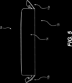
- FIG. 5 depicts closed-end side 128 of child-resistant container 100 and an exemplary configuration of locking mechanisms 112 a and 112 b in greater detail.
- locking mechanisms 112 a and 112 b may be hinged tabs extending from and attached to a lower edge of sidewall 114 .
- Locking mechanisms 112 a and 112 b may be integrally formed with the lower edge of sidewall 114 , such that they may be folded upward toward the upper surface of inner tray 104 .
- a resiliency of the hinges may cause the locking mechanisms 112 a and 112 b to be biased outwardly, away from sidewall 114 .
- locking mechanisms 112 a and 112 b may be selectively depressed inwardly by the user.
- FIGS. 6 A and 6 B depict top and bottom views, respectively, of inner tray 104 .
- locking mechanism 112 a may be positioned adjacent cut-out 110 a
- locking mechanism 112 b may be positioned adjacent cut-out 110 b .
- cut-outs 110 a and 110 b may facilitate the selective depression of locking mechanisms 112 a and 112 b .
- cut-outs 110 a and 110 b may allow for increased inward flexion of sidewall 114 , thereby permitting locking mechanisms 112 a and 112 b to be easily depressed by the user.
- inner tray 104 may be integrally formed of a thin-walled construction, such that contours of cavity 118 can be seen via a corresponding lower cavity wall 118 a in a bottom view of inner tray 104 .
- Locking mechanism 112 b may include a projection 124 extending outwardly therefrom.
- Projection 124 may be configured to engage with a locking port of outer sleeve 102 , e.g. locking port 202 a as shown in FIG. 8 A .
- Projection 124 may include a locking portion 124 a and a tactile portion 124 b .
- Locking portion 124 a may engage with a locking port of outer sleeve 102 to prevent inner tray 104 from being withdrawn from outer sleeve 102 .
- Locking portion 124 a may be, for example, a partially cylindrical shape.
- Tactile portion 124 b may be a textured, raised, or otherwise distinct portion of projection 124 , which may allow a user to easily locate and/or depress locking mechanism 112 b .
- inner tray 104 may be integrally formed of a thin-walled construction, by including locking portion 124 a and tactile portion 124 b on projection 124 in lieu of a uniform surface, projection 124 may be fortified against deformation which could render projection 124 non-functional.
- locking mechanism 112 a may include substantially the same features as locking mechanism 112 b .
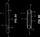
- Outer sleeve 102 may include a locking port 202 a located on a left side wall 204 a of outer sleeve 102 .
- Locking port 202 a may be in the form of a cut-out extending through left side wall 204 a and shaped to receive projection 124 as described herein previously.
- Outer sleeve 102 may further include a right side wall 204 b , a closed end 206 , a lower wall 208 , an upper wall 210 , and an open end 212 .
- right side wall 204 b may include a locking port substantially similar to locking port 202 a and positioned opposite locking port 202 a .
- each of locking mechanisms 112 a and 112 b may protrude through a respective locking port of outer sleeve 102 , thereby engaging the locking ports.
- inner tray 104 may be prevented from sliding relative to outer sleeve 102 and may therefore be prevented from being withdrawn from outer sleeve 102 .
- the user may first be required to depress each of locking mechanisms 112 a and 112 b inwardly such that the projections 124 disengage from the locking ports.
- Cut-outs 110 a and 110 b may be positioned near locking mechanisms 112 a and 112 b such that cut-outs 110 a and 110 b permit locking mechanisms 112 a and 112 b to be depressed inwardly a sufficient distance to disengage from the locking ports. Cut-outs 110 a and 110 b may further reduce the pressure necessary to depress locking mechanisms 112 a and 112 b inwardly by increasing the flexibility of inner tray 104 .
- the projections 124 When the projections 124 are disengaged from the locking ports, the user may slide inner tray 104 relative to outer sleeve 102 and accordingly may withdraw inner tray 104 at least partially from outer sleeve 102 .
- a user may depress locking mechanisms 112 a and 112 b by applying pressure with a thumb and/or fingers. For example, a user may depress locking mechanism 112 a with her thumb and may depress locking mechanism 112 b with her index finger. In some embodiments, simultaneous depression of locking mechanism 112 a and locking mechanism 112 b may be required to withdraw inner tray 104 from outer sleeve 102 . In some embodiments, depressing locking mechanism 112 a and locking mechanism 112 b at different times may permit withdrawal of inner tray 104 from outer sleeve 102 .
- open end 212 may be configured to receive inner tray 104 such that inner tray 104 is slidable with respect to outer sleeve 102 through open end 212 .
- Outer sleeve 102 may further include a left catch 214 a positioned on an interior surface of left side wall 204 a and a right catch 214 b positioned on an interior surface of right side wall 204 b .
- Left catch 214 a and right catch 214 b may be attached to left side wall 204 a and right side wall 204 b , respectively, via hinges such that left catch 214 a and right catch 214 b may swing inwardly into the space defined by outer sleeve 102 .
- the hinges may be formed by simply folding left catch 214 a and right catch 214 b inwardly.
- left catch 214 a and right catch 214 b may be separately formed components that are adhered or otherwise attaching to 204a// and 204b//, respectively.
- Catches 214 a and 214 b may be folded into sleeve 102 and secured therein by, e.g., a suitable adhesive.
- left catch 214 a and right catch 214 b may each be caused to fold about their respective hinged attachments by inner tray 104 .
- left catch 214 a may be parallel or substantially parallel to an interior surface of left side wall 204 a .
- right catch 214 b may be parallel or substantially parallel to an interior surface of right side wall 204 b .
- left catch 214 a and right catch 214 b may interfere with locking mechanisms 112 a and 112 b to prevent inner tray 104 from being fully withdrawn from outer sleeve 102 .
- the user may depress locking mechanisms 112 a and 112 b , thereby disengaging them from the respective locking ports. The user may then slide inner tray 104 relative to outer sleeve 102 outwardly through open end 212 .
- locking mechanism 112 a Before inner tray 104 is fully withdrawn from outer sleeve 102 , locking mechanism 112 a may engage with left catch 214 a and locking mechanism 112 b may engage with right catch 214 b . Locking mechanisms 112 a and 112 b may thus be prevented from moving further relative to outer sleeve 102 toward open end 212 . Consequently, inner tray 104 may likewise be prevented from moving further by virtue of locking mechanisms 112 a and 112 b being attached thereto.
- left catch 214 a and right catch 214 b may permit inner tray 104 to be withdrawn from outer sleeve 102 to a position in which the contents of child-resistant container 100 may be accessible to a user, i.e. a contents-accessible position.
- locking mechanisms 112 a and 112 b may engage with catches 214 a and 214 b to prevent further movement of the inner tray 104 relative to outer sleeve 102 .
- sealing substrate 106 may be peeled from inner tray 104 , thereby exposing an entirety of cavity 118 and any contents that may be stored therein.
- outer sleeve 102 may continue to cover upper planar surface 110 and adhering strip 116 , thereby helping to maintain adhering strip 116 in place on upper planar surface 110 .
- sealing substrate 106 may remain in a position to be easily resealed to inner tray 104 by a user.
- Locking mechanisms 112 a and 112 b as described herein may therefore serve in a multi-functional capacity on child-resistant container 100 .
- locking mechanisms 112 a and 112 b may serve as a means by which a user can selectively secure the contents of child-resistant container 100 .
- locking mechanisms 112 a and 112 b may effectively prevent children from accessing contents of child-resistant container 100 which may be hazardous.
- locking mechanisms 112 a and 112 b may prevent a user from inadvertently disassembling child-resistant container 100 and may further facilitate repeated opening and closing of child-resistant container 100 . Furthermore, by configuring locking mechanisms 112 a and 112 b in the manner described herein, the various aforementioned functionalities may be incorporated into child-resistant container 100 while minimizing the quantity and complexity of structural features included on child-resistant container 100 . Accordingly, child-resistant container 100 may be formed by simple and cost-effective manufacturing processes suitable for mass production and retail distribution.
Landscapes
- Engineering & Computer Science (AREA)
- Mechanical Engineering (AREA)
- Packages (AREA)
Abstract
A child-resistant container may include an inner tray including a first side, a second side opposite the first side, a first locking mechanism on the first side, and a second locking mechanism on the second side; and an outer sleeve including a first sleeve side, a second sleeve side opposite the first sleeve side, a first locking port on the first sleeve side, a second locking port on the second sleeve side, an open end, and one or more catches. The inner tray may be slidably inserted into the outer sleeve through the open end such that each of the locking mechanisms releasably engages at least one of the locking ports. At least one of the locking mechanisms may engage with the one or more catches to prevent the inner tray from being fully withdrawn from the outer sleeve.
Description
- Embodiments of the present disclosure relate generally to small containers and more specifically containers with child-resistant features, and related methods of use thereof.
- Portable, child-resistant containers may be useful for a variety of applications. For example, such containers may be used to store medications, tobacco products, cannabis products, or other products and substances that may be hazardous to children. Ideally, such containers may be lightweight, may be easily opened for access to the contents, may be easily closed to keep the contents fresh, and may include a mechanism suitable for preventing children from accessing the contents. Existing containers may lack these desirable features and may be constructed in a manner that is inefficient for mass production. Accordingly, existing containers may be unsuitable for storage of the items described and existing containers may also be unsuitable for retail distribution of various products.
- As such, there exists a need for improved child-resistant containers and methods of using the same to provide users with desirable features and functionality via a container that can be manufactured in a low-cost and efficient manner.
- The present disclosure is directed to addressing the above-referenced challenges. The background description provided herein is for the purpose of generally presenting the context of the disclosure. Unless otherwise indicated herein, the materials described in this section are not prior art to the claims in this application and are not admitted to be prior art, or suggestions of the prior art, by inclusion in this section.
- According to certain aspects of the disclosure, child-resistant containers and methods for using the same are described.
- In one example, a child-resistant container may include: an inner tray including a first side, a second side opposite the first side, a first locking mechanism on the first side, and a second locking mechanism on the second side; and an outer sleeve including a first sleeve side, a second sleeve side opposite the first sleeve side, a first locking port on the first sleeve side, a second locking port on the second sleeve side, an open end, and one or more catches located on an interior of the outer sleeve toward the open end. The inner tray may be configured to be slidably inserted into the outer sleeve through the open end such that each of the locking mechanisms releasably engages at least one of the locking ports upon insertion of the inner tray into the outer sleeve; and at least one of the locking mechanisms may be further configured, upon sliding the inner tray outwardly through the open end of the outer sleeve, to engage with the one or more catches to prevent the inner tray from being fully withdrawn from the outer sleeve.
- In another example, a child-resistant container may include: an inner tray including a first side and a first locking mechanism positioned on the first side; and an outer sleeve including a first sleeve side, a first locking port on the first sleeve side, an open end, and a catch located on an interior of the outer sleeve toward the open end. The inner tray may be configured to be slidably inserted into the outer sleeve through the open end such that the locking mechanism releasably engages the locking port upon insertion of the inner tray into the outer sleeve; and the locking mechanism may be further configured, upon sliding the inner tray outwardly through the open end of the outer sleeve, to engage with the catch to prevent the inner tray from being fully withdrawn from the outer sleeve.
- In still another example, a method of accessing contents of a child-resistant container comprising an inner tray positioned with an outer sleeve may include: disengaging a first locking mechanism of the inner tray from a first locking port of the outer sleeve and a second locking mechanism of the inner tray from a second locking port of the outer sleeve; withdrawing the tray through an open end of the outer sleeve until at least one of the first locking mechanism and the second locking mechanism engages with at least one catch positioned on an interior of the outer sleeve to prevent the inner tray from being fully withdrawn from the outer sleeve; and accessing the contents located in a cavity of the inner tray.
- Additional objects and advantages of the disclosed embodiments will be set forth in part in the description that follows, and in part will be apparent from the description, or may be learned by practice of the disclosed embodiments.
- It is to be understood that both the foregoing general description and the following detailed description are exemplary and explanatory only and are not restrictive of the disclosed embodiments, as claimed.
- The accompanying drawings, which are incorporated in and constitute a part of this specification, illustrate various exemplary embodiments and together with the description, serve to explain the principles of the disclosed embodiments.
-
FIG. 1 depicts an isometric view of a container according to some embodiments. -
FIG. 2 depicts an isometric view of a container in a partially exploded configuration according to some embodiments. -
FIG. 3A depicts an isometric view of a tray of a container according to some embodiments. -
FIG. 3B depicts an isometric view of a tray of a container according to some embodiments. -
FIG. 4 depicts an isometric view of a tray of a container according to some embodiments. -
FIG. 5 depicts a rear view of a tray according to some embodiments. -
FIG. 6A depicts a top view of a tray according to some embodiments. -
FIG. 6B depicts a bottom view of a tray according to some embodiments. -
FIG. 7 depicts an isometric view of a locking tab according to some embodiments. -
FIG. 8A depicts a side view of a sleeve according to some embodiments. -
FIG. 8B depicts a front view of a sleeve according to some embodiments. -
FIG. 9 depicts an isometric view of a container in an exploded configuration according to some embodiments. -
FIG. 10 depicts an isometric view of a container in an exploded configuration according to some embodiments. - The terminology used below may be interpreted in its broadest reasonable manner, even though it is being used in conjunction with a detailed description of certain specific examples of the present disclosure. Indeed, certain terms may even be emphasized below; however, any terminology intended to be interpreted in any restricted manner will be overtly and specifically defined as such in this Detailed Description section. Both the foregoing general description and the following detailed description are exemplary and explanatory only and are not restrictive of the features, as claimed.
- In this disclosure, the term “based on” means “based at least in part on.” The singular forms “a,” “an,” and “the” include plural referents unless the context dictates otherwise. The term “exemplary” is used in the sense of “example” rather than “ideal.” The terms “comprises,” “comprising,” “includes,” “including,” or other variations thereof, are intended to cover a non-exclusive inclusion such that a process, method, or product that comprises a list of elements does not necessarily include only those elements, but may include other elements not expressly listed or inherent to such a process, method, article, or apparatus. Relative terms such as “substantially” and “generally” are used to indicate a possible variation of ±10% of a stated or understood value.
- In general, the present disclosure is directed to improved, child-resistant containers and methods for using the same. The devices and methods described in the present disclosure offer significant technical benefits which will become apparent.
- Portable, child-resistant containers may be useful for storing medications, tobacco products, cannabis products, or other products and substances that may be hazardous to children. As one example, such containers may be used to store pre-rolled tobacco or cannabis cigarettes. In such an application, a child-resistant container may serve multiple functions, such as protecting the contents from physical damage during shipment, maintaining the freshness of the contents before use, providing a means for a user to safely and easily transport the contents, and preventing access by children to whom the contents may be hazardous or toxic.
- It may be desirable for child-resistant containers to be sufficiently rigid to protect the contents, for example, during shipment to a retail location or to an end user. If the contents of a container include pre-rolled cigarettes, the container may protect the cigarettes from physical damage during shipment. The container may further be suitable for and allow packing of large quantities of similar containers without buckling or flattening.
- It may also be desirable for child-resistant containers to be easily opened and resealed such that the contents need not be removed from the container all at once. For example, a user may wish to open such a container to remove one of multiple cigarettes for immediate use and reseal the remaining cigarettes in the container. That way, the user may save the remaining cigarettes for later use in the container, thereby preventing the cigarettes from becoming stale and also preventing access of the remaining cigarettes by children. The container may further allow the user to easily transport the remaining cigarettes in a pocket, for example, without risking crushing, tearing, or other physical damage to the cigarettes.
- It may further be desirable for child-resistant containers to include a mechanism suitable for preventing children from accessing the contents of the containers while simultaneously being easily operable by the intended user. An easily operable mechanism may be operated manually, requiring minimal force and not requiring tools. An easily operable mechanism may also be sufficiently complex so as to inhibit a child from opening the container, but not so complex that an adult could not readily open the container.
- Additionally, it may be desirable for child-resistant containers incorporating one or more of the foregoing features to be formed of a simple construction to enable efficient and low-cost manufacturing. When configured in such a manner, containers may be suitable for use in high-volume packaging applications without significantly contributing to a cost of the end product stored within the containers.
- Accordingly, a need exists for improved child-resistant containers and methods of using the same to provide users with the desirable features described herein via a container that can be manufactured in a low-cost and efficient manner. Embodiments of the present disclosure offer technical solutions to address the foregoing needs, as well as other needs.
-
FIG. 1 depicts an exemplary child-resistant container 100 in accordance with the present disclosure. Child-resistant container 100 may include anouter sleeve 102 and aninner tray 104. As shown inFIG. 1 ,inner tray 104 may be positioned withinouter sleeve 102 when the child-resistant container 100 is in a closed configuration. In the closed configuration, child-resistant container 100 may enclose contents stored therein, such as pre-rolled cigarettes or the like. In the closed configuration, a user may be prevented from simply withdrawinginner tray 104 fromouter sleeve 102 without taking additional steps, which will be described in greater detail hereinafter. - In the closed configuration, child-
resistant container 100 may be compact for convenient transport by a user, such as in a pocket of an article of clothing, in a purse, or the like. In some embodiments, child-resistant container 100 may be about 5 inches long, about 2.5 inches wide, and about 0.5 inches thick. Though exemplary dimensions are provided herein, these dimensions are not intended to be limiting and it should be understood that the dimensions of child-resistant container 100 may vary. -
FIG. 2 depicts child-resistant container 100 in a partially exploded configuration, i.e., withinner tray 104 fully withdrawn fromouter sleeve 102.Outer sleeve 102 may be formed of a generally hollow construction, having a space therein sized to accommodateinner tray 104. In some embodiments,outer sleeve 102 may be formed, for example, of a folded paper material such as paperboard, cardboard, or the like. In some embodiments,outer sleeve 102 may alternatively be formed of molded plastic materials such as polyethylene terephthalate (PET), high-density polyethylene (HDPE), polyvinyl chloride (PVC), low-density polyethylene (LDPE), polypropylene (PP) or polystyrene. In some embodiments,outer sleeve 102 may be formed from a plastic sheet that is folded into shape. In some embodiments,outer sleeve 102 may formed of a stamped metal material such as aluminum, tin, or the like. In some embodiments,outer sleeve 102 may be formed of a combination of any of the foregoing materials. -
Inner tray 104 may be dimensioned so as to substantially occupy the space withinouter sleeve 102. For example,inner tray 104 may be sized such that a clearance fit is created betweenouter sleeve 102 andinner tray 104, thereby allowing a user to slideinner tray 104 relative toouter sleeve 102.Inner tray 104 may be formed of molded plastic materials such as PET, HDPE, PVC, LDPE, PP, or polystyrene. In some embodiments,inner tray 104 may be formed of a stamped metal material such as aluminum or tin. In some embodiments,inner tray 104 may be formed of a folded paper material. In some embodiments,inner tray 104 may be formed of a combination of any of the foregoing materials, such as a folded paper material with plastic and/or metal components. -
Inner tray 104 may include a sealingsubstrate 106 configured to seal the contents of child-resistant container 100 withininner tray 104.Sealing substrate 106 may be a flexible material and may include an adhesive disposed on a lower side thereof.Sealing substrate 106 may be formed from a plastic film, aluminum foil, paper, paper laminated with a plastic film, or any other suitable flexible material. The adhesive may adhere to an upper surface ofinner tray 104 such that it may be selectively peeled frominner tray 104 by the user to reveal or otherwise provide access to the contents of child-resistant container 100.Sealing substrate 106 may serve, for example, to maintain freshness of the contents and/or to prevent contamination of the contents by impurities. In some embodiments, sealingsubstrate 106 may be transparent or translucent to allow a user to see the contents of child-resistant container 100 without peeling sealingsubstrate 106. - Referring to
FIG. 3A , sealingsubstrate 106 may include apull tab 108 disposed toward an open-end side 126 ofinner tray 104, where the open-end side 126 is a side exposed when child-resistant container 100 is in a closed state, as shown inFIG. 1 .Pull tab 108 may extend over the open-end side 126 ofinner tray 104 such that a user may easily grasppull tab 108 to peel sealingsubstrate 106 frominner tray 104 to access the contents ofinner tray 104. In some embodiments,pull tab 108 may extend out ofouter sleeve 102 when child-resistant container 100 is in a closed state, thereby permitting the user to withdrawinner tray 104 fromouter sleeve 102 viapull tab 108.Pull tab 108 may have any suitable configuration. -
Inner tray 104 may further include an upperplanar surface 110 positioned opposite the open-end side 126 toward a distal side ofinner tray 104. Upperplanar surface 110 may include cut-outs outs planar surface 110, extending throughinner tray 104. Cut-outs inner tray 104, which is opposite the open-end side 126. Cut-outs inner tray 104. Upperplanar surface 110 may further accommodate an adheringstrip 116 of sealingsubstrate 106. Adheringstrip 116 may be a portion of sealingsubstrate 106 having an adhesive on a lower side thereof that may serve to maintain an orientation of sealingsubstrate 106 relative toinner tray 104 when sealingsubstrate 106 is peeled. Adheringstrip 116 may further be shaped so as to adhere between cut-outs planar surface 110. -
Inner tray 104 may include asidewall 114 extending around the perimeter ofinner tray 104.Inner tray 104 may also include lockingmechanisms sidewall 114 on left and right sides of theinner tray 104, respectively. Lockingmechanisms ports 202 a ofouter sleeve 102, as described hereinafter in greater detail, to prevent opening of child-resistant container 100 by a child. Lockingmechanisms outer sleeve 102. Lockingmechanisms end side 128 ofinner tray 104. - In some embodiments, and as shown in
FIG. 3B ,pull tab 108 may be folded down againstsidewall 114. In some embodiments,pull tab 108 may include adhesive applied to an underside thereof such thatpull tab 108 may be adhered tosidewall 114 when folded down.Pull tab 108 may further include agrip portion 130, an underside of which does not include adhesive applied thereto.Grip portion 130 may be hemispherical, triangular, rectangular, or any other shape.Grip portion 130 may allow a user to more easily position a finger or other object betweenpull tab 108 andsidewall 114 to releasepull tab 108 fromsidewall 114 when removing sealingsubstrate 106 frominner tray 104. By foldingpull tab 108 down againstsidewall 114 and adhering it thereto, the seal of sealingsubstrate 106 toinner tray 104 may be enhanced and/or further secured. - Referring to
FIG. 4 , to access the contents of child-resistant container 100, a user may peel sealingsubstrate 106 frominner tray 104 to exposecavity 118.Cavity 118 may be a space formed withininner tray 104 configured to store or retain medications, pre-rolled cigarettes, edible products, or any other items suitable for storage in child-resistant container 100. In some embodiments,cavity 118 include a single space, as shown inFIG. 4 . Alternatively, in some embodiments,cavity 118 may be subdivided into multiple spaces. For example,cavity 118 may include multiple discrete spaces, each of which is configured to store one or more pre-rolled cigarettes. -
Sealing substrate 106 may be adhered to one or more ofleft edge 120 a,right edge 120 b, or open-end edge 122, each of whichborder cavity 118.Sealing substrate 106 may be peeled initially from open-end edge 122, then fromleft edge 120 a andright edge 120 b to expose the contents stored incavity 118. As shown, sealingsubstrate 106 need not necessarily be removed entirely frominner tray 104 and may indeed remain partially adhered toinner tray 104 while a user accesses the contents. For example, adheringstrip 116 of sealingsubstrate 106 may remain adhered to upperplanar surface 110 while a user accesses the contents incavity 118. Accordingly, an orientation of sealingsubstrate 106 relative toinner tray 104 may be maintained so that sealingsubstrate 106 may easily be re-adhered toinner tray 104, thereby resealingcavity 118. Such a configuration may be particularly useful, for example, for a user who wishes to remove one of several items fromcavity 118 and preserve the freshness of the remaining items. -
FIG. 5 depicts closed-end side 128 of child-resistant container 100 and an exemplary configuration of lockingmechanisms mechanisms sidewall 114. Lockingmechanisms sidewall 114, such that they may be folded upward toward the upper surface ofinner tray 104. Upon folding of lockingmechanisms inner tray 104, a resiliency of the hinges may cause the lockingmechanisms sidewall 114. As a result of the outward biasing, lockingmechanisms -
FIGS. 6A and 6B depict top and bottom views, respectively, ofinner tray 104. As shown,locking mechanism 112 a may be positioned adjacent cut-out 110 a, andlocking mechanism 112 b may be positioned adjacent cut-out 110 b. In such a configuration, cut-outs mechanisms outs sidewall 114, thereby permitting lockingmechanisms - As shown in
FIG. 6B ,inner tray 104 may be integrally formed of a thin-walled construction, such that contours ofcavity 118 can be seen via a correspondinglower cavity wall 118 a in a bottom view ofinner tray 104. - Referring to
FIG. 7 , features of anexemplary locking mechanism 112 b will be described in greater detail.Locking mechanism 112 b may include aprojection 124 extending outwardly therefrom.Projection 124 may be configured to engage with a locking port ofouter sleeve 102, e.g. lockingport 202 a as shown inFIG. 8A .Projection 124 may include a lockingportion 124 a and atactile portion 124 b. Lockingportion 124 a may engage with a locking port ofouter sleeve 102 to preventinner tray 104 from being withdrawn fromouter sleeve 102. Lockingportion 124 a may be, for example, a partially cylindrical shape.Tactile portion 124 b may be a textured, raised, or otherwise distinct portion ofprojection 124, which may allow a user to easily locate and/or depresslocking mechanism 112 b. Further, asinner tray 104 may be integrally formed of a thin-walled construction, by including lockingportion 124 a andtactile portion 124 b onprojection 124 in lieu of a uniform surface,projection 124 may be fortified against deformation which could renderprojection 124 non-functional. Though not shown inFIG. 7 ,locking mechanism 112 a may include substantially the same features as lockingmechanism 112 b. - Referring to
FIGS. 8A and 8B ,outer sleeve 102 will be described in greater detail.Outer sleeve 102 may include a lockingport 202 a located on aleft side wall 204 a ofouter sleeve 102. Lockingport 202 a may be in the form of a cut-out extending throughleft side wall 204 a and shaped to receiveprojection 124 as described herein previously.Outer sleeve 102 may further include aright side wall 204 b, aclosed end 206, alower wall 208, anupper wall 210, and anopen end 212. Though not shown,right side wall 204 b may include a locking port substantially similar to lockingport 202 a and positioned opposite lockingport 202 a. - When
inner tray 104 is fully inserted intoouter sleeve 102, therespective projections 124 on each of lockingmechanisms outer sleeve 102, thereby engaging the locking ports. When theprojections 124 engage the locking ports,inner tray 104 may be prevented from sliding relative toouter sleeve 102 and may therefore be prevented from being withdrawn fromouter sleeve 102. For a user to be able to withdrawinner tray 104 fromouter sleeve 102, the user may first be required to depress each of lockingmechanisms projections 124 disengage from the locking ports. Cut-outs mechanisms outs permit locking mechanisms outs mechanisms inner tray 104. When theprojections 124 are disengaged from the locking ports, the user may slideinner tray 104 relative toouter sleeve 102 and accordingly may withdrawinner tray 104 at least partially fromouter sleeve 102. - In some embodiments, a user may depress locking
mechanisms locking mechanism 112 a with her thumb and may depresslocking mechanism 112 b with her index finger. In some embodiments, simultaneous depression oflocking mechanism 112 a andlocking mechanism 112 b may be required to withdrawinner tray 104 fromouter sleeve 102. In some embodiments, depressinglocking mechanism 112 a andlocking mechanism 112 b at different times may permit withdrawal ofinner tray 104 fromouter sleeve 102. - Referring to
FIG. 8B ,open end 212 may be configured to receiveinner tray 104 such thatinner tray 104 is slidable with respect toouter sleeve 102 throughopen end 212.Outer sleeve 102 may further include aleft catch 214 a positioned on an interior surface ofleft side wall 204 a and aright catch 214 b positioned on an interior surface ofright side wall 204 b.Left catch 214 a andright catch 214 b may be attached toleft side wall 204 a andright side wall 204 b, respectively, via hinges such thatleft catch 214 a andright catch 214 b may swing inwardly into the space defined byouter sleeve 102. In some embodiments, the hinges may be formed by simply foldingleft catch 214 a andright catch 214 b inwardly. In some embodiments,left catch 214 a andright catch 214 b may be separately formed components that are adhered or otherwise attaching to 204a// and 204b//, respectively.Catches sleeve 102 and secured therein by, e.g., a suitable adhesive. - Upon insertion of
inner tray 104 throughopen end 212 and into the space defined byouter sleeve 102,left catch 214 a andright catch 214 b may each be caused to fold about their respective hinged attachments byinner tray 104. Wheninner tray 104 is positioned withinouter sleeve 102,left catch 214 a may be parallel or substantially parallel to an interior surface ofleft side wall 204 a. Similarly, wheninner tray 104 is positioned withinouter sleeve 102,right catch 214 b may be parallel or substantially parallel to an interior surface ofright side wall 204 b. - When the
inner tray 104 is positioned withinouter sleeve 102 and left catch 214 a andright catch 214 b are positioned along the respective sidewalls,left catch 214 a andright catch 214 b may interfere with lockingmechanisms inner tray 104 from being fully withdrawn fromouter sleeve 102. For example, when child-resistant container 100 is in a closed configuration (FIG. 1 ) and the user wishes to access the contents stored within child-resistant container 100, the user may depress lockingmechanisms inner tray 104 relative toouter sleeve 102 outwardly throughopen end 212. Beforeinner tray 104 is fully withdrawn fromouter sleeve 102,locking mechanism 112 a may engage withleft catch 214 a andlocking mechanism 112 b may engage withright catch 214 b. Lockingmechanisms outer sleeve 102 towardopen end 212. Consequently,inner tray 104 may likewise be prevented from moving further by virtue of lockingmechanisms - Referring to
FIGS. 9 and 10 ,left catch 214 a andright catch 214 b may permitinner tray 104 to be withdrawn fromouter sleeve 102 to a position in which the contents of child-resistant container 100 may be accessible to a user, i.e. a contents-accessible position. In the contents-accessible position, lockingmechanisms catches inner tray 104 relative toouter sleeve 102. Further, in the contents-accessible position, sealingsubstrate 106 may be peeled frominner tray 104, thereby exposing an entirety ofcavity 118 and any contents that may be stored therein. In the contents-accessible position,outer sleeve 102 may continue to cover upperplanar surface 110 and adheringstrip 116, thereby helping to maintain adheringstrip 116 in place on upperplanar surface 110. As a result, when a user peels sealingsubstrate 106 frominner tray 104, sealingsubstrate 106 may remain in a position to be easily resealed toinner tray 104 by a user. - Locking
mechanisms resistant container 100. In conjunction with the locking ports (e.g. 202 a and a similar locking port on an opposite side of outer sleeve 102), lockingmechanisms resistant container 100. In this way, lockingmechanisms resistant container 100 which may be hazardous. In conjunction withleft catch 214 a andright catch 214 b, lockingmechanisms resistant container 100 and may further facilitate repeated opening and closing of child-resistant container 100. Furthermore, by configuringlocking mechanisms resistant container 100 while minimizing the quantity and complexity of structural features included on child-resistant container 100. Accordingly, child-resistant container 100 may be formed by simple and cost-effective manufacturing processes suitable for mass production and retail distribution. - Although the exemplary embodiments described above have been disclosed in connection with a child-resistant container, those skilled in the art will understand that the principles set out above can be applied to any container and can be implemented in different ways without departing from the scope of the disclosure as defined by the claims. In particular, construction details, including manufacturing techniques and materials, are well within the understanding of those of skill in the art and have not been set out in detail here. These and other modifications and variations are well within the scope of the present disclosure and can be envisioned and implemented by those of skill in the art.
- Other exemplary embodiments of the present disclosure will be apparent to those skilled in the art from consideration of the specification and practice of the exemplary embodiments disclosed herein. It is intended that the specification and examples be considered as exemplary only, and departures in form and detail may be made without departing from the scope and spirit of the present disclosure as defined by the following claims.
Claims (22)
1. A child-resistant container, comprising:
an inner tray including a first side, a second side opposite the first side, a first locking mechanism on the first side, and a second locking mechanism on the second side; and
an outer sleeve including a first sleeve side, a second sleeve side opposite the first sleeve side, a first locking port on the first sleeve side, a second locking port on the second sleeve side, an open end, and one or more catches located on an interior of the outer sleeve toward the open end;
wherein the inner tray is configured to be slidably inserted into the outer sleeve through the open end such that each of the locking mechanisms releasably engages at least one of the locking ports upon insertion of the inner tray into the outer sleeve; and
wherein at least one of the locking mechanisms is further configured, upon sliding the inner tray outwardly through the open end of the outer sleeve, to engage with the one or more catches to prevent the inner tray from being fully withdrawn from the outer sleeve.
2. The child-resistant container of claim 1 , wherein the locking mechanisms are configured, when engaged with the locking ports, to prevent the inner tray from being withdrawn through the open end of the outer sleeve.
3. The child-resistant container of claim 1 , wherein the first locking mechanism includes a first projection and the second locking mechanism includes a second projection; and
wherein the first projection protrudes through the first locking port when the first locking mechanism engages the first locking port and the second projection protrudes through the second locking port when the second locking mechanism engages the second locking port.
4. The child-resistant container of claim 3 , wherein the first locking mechanism is configured to disengage from the first locking port upon depression of the first projection and the second locking mechanism is configured to disengage from the second locking port upon depression of the second projection.
5. The child-resistant container of claim 4 , wherein upon depression of the first projection and the second projection, the inner tray is permitted to be withdrawn outwardly through the open end of the outer sleeve.
6. The child-resistant container of claim 1 , wherein the inner tray further includes a third side and a fourth side opposite the third side, the third side located at the open end of the outer sleeve when the inner tray is inserted in the outer sleeve; and
wherein the first locking mechanism and the second locking mechanism are positioned adjacent the fourth side.
7. The child-resistant container of claim 6 , wherein the one or more catches are positioned adjacent the third side when the inner tray is inserted in the outer sleeve.
8. The child-resistant container of claim 7 , wherein the one or more catches includes a first catch and a second catch, the first catch configured to engage with the first locking mechanism and the second catch configured to engage with the second locking mechanism.
9. The child-resistant container of claim 6 , wherein the inner tray further includes a first cut-out positioned adjacent the first locking mechanism, the first cut-out configured to facilitate disengagement of the first locking mechanism from the first locking port.
10. The child-resistant container of claim 1 , wherein the inner tray is integrally formed of a molded plastic.
11. The child-resistant container of claim 10 , wherein the outer sleeve is formed of a folded paper material or a folded plastic sheet.
12. The child-resistant container of claim 10 , wherein the inner tray further includes one or more cavities configured to retain contents of the child-resistant container.
13. The child-resistant container of claim 12 , wherein the inner tray further includes a substrate configured to selectively seal the one or more cavities.
14. A child-resistant container, comprising:
an inner tray including a first side and a first locking mechanism positioned on the first side; and
an outer sleeve including a first sleeve side, a first locking port on the first sleeve side, an open end, and a catch located on an interior of the outer sleeve toward the open end;
wherein the inner tray is configured to be slidably inserted into the outer sleeve through the open end such that the locking mechanism releasably engages the locking port upon insertion of the inner tray into the outer sleeve; and
wherein the locking mechanism is further configured, upon sliding the inner tray outwardly through the open end of the outer sleeve, to engage with the catch to prevent the inner tray from being fully withdrawn from the outer sleeve.
15. The child-resistant container of claim 14 , wherein the locking mechanism is configured, when engaged with the locking port, to prevent the inner tray from sliding outwardly through the open end of the outer sleeve.
16. The child-resistant container of claim 14 , wherein the first locking mechanism includes a first projection; and
wherein the first projection protrudes through the first locking port when the first locking mechanism engages the first locking port and the first locking mechanism is configured to be disengaged from the first locking port upon depression of the first projection.
17. The child-resistant container of claim 14 , wherein the inner tray further includes a third side and a fourth side opposite the third side, the third side being located within the open end of the outer sleeve when the inner tray is inserted in the outer sleeve; and
wherein the first locking mechanism is positioned adjacent the fourth side.
18. The child-resistant container of claim 17 , wherein the catches is positioned adjacent the third side when the inner tray is inserted in the outer sleeve.
19. The child-resistant container of claim 16 , wherein upon depression of the first projection, the inner tray is permitted to slide outwardly through the open end of the outer sleeve.
20. A method of accessing contents of a child-resistant container comprising an inner tray positioned with an outer sleeve, the method comprising:
disengaging a first locking mechanism of the inner tray from a first locking port of the outer sleeve and a second locking mechanism of the inner tray from a second locking port of the outer sleeve;
withdrawing the inner tray through an open end of the outer sleeve until at least one of the first locking mechanism and the second locking mechanism engages with at least one catch positioned on an interior of the outer sleeve to prevent the inner tray from being fully withdrawn from the outer sleeve; and
accessing the contents located in a cavity of the inner tray.
21. The method of claim 20 , further comprising:
after withdrawing the inner tray, peeling a substrate partially from the inner tray such that the cavity is unsealed and the substrate remains adhered to at least a portion of the inner tray.
22. The method of claim 21 , further comprising:
repositioning the substrate on the inner tray such that the cavity is resealed.
Priority Applications (2)
| Application Number | Priority Date | Filing Date | Title |
|---|---|---|---|
| US17/454,084 US20230150737A1 (en) | 2021-11-09 | 2021-11-09 | Child-resistant container |
| CA3181622A CA3181622A1 (en) | 2021-11-09 | 2022-11-08 | Child-resistant container |
Applications Claiming Priority (1)
| Application Number | Priority Date | Filing Date | Title |
|---|---|---|---|
| US17/454,084 US20230150737A1 (en) | 2021-11-09 | 2021-11-09 | Child-resistant container |
Publications (1)
| Publication Number | Publication Date |
|---|---|
| US20230150737A1 true US20230150737A1 (en) | 2023-05-18 |
Family
ID=86282197
Family Applications (1)
| Application Number | Title | Priority Date | Filing Date |
|---|---|---|---|
| US17/454,084 Abandoned US20230150737A1 (en) | 2021-11-09 | 2021-11-09 | Child-resistant container |
Country Status (2)
| Country | Link |
|---|---|
| US (1) | US20230150737A1 (en) |
| CA (1) | CA3181622A1 (en) |
Cited By (2)
| Publication number | Priority date | Publication date | Assignee | Title |
|---|---|---|---|---|
| US20230391518A1 (en) * | 2022-06-02 | 2023-12-07 | OnSpec Solutions Incorporated | Child Proof Substance Container Assembly |
| US20250221557A1 (en) * | 2024-01-09 | 2025-07-10 | Natalie R. Wilson | Snack board |
Citations (19)
| Publication number | Priority date | Publication date | Assignee | Title |
|---|---|---|---|---|
| US1925316A (en) * | 1931-07-18 | 1933-09-05 | Bridgeport Metal Goods Mfg Co | Vanity box |
| US4561544A (en) * | 1983-12-28 | 1985-12-31 | Calmar, Inc. | Child resistant container |
| US4898195A (en) * | 1985-06-03 | 1990-02-06 | Shore Plastics, Inc. | Sliding drawer cosmetic compact |
| US20020056652A1 (en) * | 2000-11-15 | 2002-05-16 | Ykk Corporation | Small article case |
| US6976576B2 (en) * | 2003-05-16 | 2005-12-20 | Intini Thomas D | Child-resistant dispenser |
| US20090152134A1 (en) * | 2004-04-20 | 2009-06-18 | Nick Katsis | Childproof Package |
| US20110036743A1 (en) * | 2007-08-17 | 2011-02-17 | Duff Design Limited | Packaging |
| US20110139864A1 (en) * | 2008-07-01 | 2011-06-16 | Alfred Wipf | Reclosable pack |
| US8091709B2 (en) * | 2006-06-09 | 2012-01-10 | Rexam Healthcare Packaging Inc. | Child-resistant package |
| US20120043323A1 (en) * | 2009-05-05 | 2012-02-23 | Meadwestvaco Corporation | Resealable packages |
| US20160152373A1 (en) * | 2013-07-04 | 2016-06-02 | Ecobliss Holding B.V. | A package as well as a slide and a housing suitable for such a package |
| US20160251107A1 (en) * | 2015-02-27 | 2016-09-01 | Munson Whitman Everett | Child-Resistant Packaging Systems and Methods |
| US20200087021A1 (en) * | 2018-09-18 | 2020-03-19 | Denali Innovations, Llc | Child-resistant packaging |
| US20200115095A1 (en) * | 2018-10-12 | 2020-04-16 | Duallok Limited | In latchable packaging |
| WO2021016197A1 (en) * | 2019-07-21 | 2021-01-28 | 14Th Round Inc. | Biodegradable child resistant packaging container |
| US20210047072A1 (en) * | 2019-08-14 | 2021-02-18 | The Procter & Gamble Company | Consumer product |
| US11046476B2 (en) * | 2016-01-28 | 2021-06-29 | Duff Design Limited | Latchable package |
| US20220135291A1 (en) * | 2020-11-05 | 2022-05-05 | Zenpack | Child-Proof Container |
| US20220371769A1 (en) * | 2019-10-07 | 2022-11-24 | Philip Morris Products S.A. | Container having outer sleeve and inner tray with locking mechanism |
-
2021
- 2021-11-09 US US17/454,084 patent/US20230150737A1/en not_active Abandoned
-
2022
- 2022-11-08 CA CA3181622A patent/CA3181622A1/en active Pending
Patent Citations (19)
| Publication number | Priority date | Publication date | Assignee | Title |
|---|---|---|---|---|
| US1925316A (en) * | 1931-07-18 | 1933-09-05 | Bridgeport Metal Goods Mfg Co | Vanity box |
| US4561544A (en) * | 1983-12-28 | 1985-12-31 | Calmar, Inc. | Child resistant container |
| US4898195A (en) * | 1985-06-03 | 1990-02-06 | Shore Plastics, Inc. | Sliding drawer cosmetic compact |
| US20020056652A1 (en) * | 2000-11-15 | 2002-05-16 | Ykk Corporation | Small article case |
| US6976576B2 (en) * | 2003-05-16 | 2005-12-20 | Intini Thomas D | Child-resistant dispenser |
| US20090152134A1 (en) * | 2004-04-20 | 2009-06-18 | Nick Katsis | Childproof Package |
| US8091709B2 (en) * | 2006-06-09 | 2012-01-10 | Rexam Healthcare Packaging Inc. | Child-resistant package |
| US20110036743A1 (en) * | 2007-08-17 | 2011-02-17 | Duff Design Limited | Packaging |
| US20110139864A1 (en) * | 2008-07-01 | 2011-06-16 | Alfred Wipf | Reclosable pack |
| US20120043323A1 (en) * | 2009-05-05 | 2012-02-23 | Meadwestvaco Corporation | Resealable packages |
| US20160152373A1 (en) * | 2013-07-04 | 2016-06-02 | Ecobliss Holding B.V. | A package as well as a slide and a housing suitable for such a package |
| US20160251107A1 (en) * | 2015-02-27 | 2016-09-01 | Munson Whitman Everett | Child-Resistant Packaging Systems and Methods |
| US11046476B2 (en) * | 2016-01-28 | 2021-06-29 | Duff Design Limited | Latchable package |
| US20200087021A1 (en) * | 2018-09-18 | 2020-03-19 | Denali Innovations, Llc | Child-resistant packaging |
| US20200115095A1 (en) * | 2018-10-12 | 2020-04-16 | Duallok Limited | In latchable packaging |
| WO2021016197A1 (en) * | 2019-07-21 | 2021-01-28 | 14Th Round Inc. | Biodegradable child resistant packaging container |
| US20210047072A1 (en) * | 2019-08-14 | 2021-02-18 | The Procter & Gamble Company | Consumer product |
| US20220371769A1 (en) * | 2019-10-07 | 2022-11-24 | Philip Morris Products S.A. | Container having outer sleeve and inner tray with locking mechanism |
| US20220135291A1 (en) * | 2020-11-05 | 2022-05-05 | Zenpack | Child-Proof Container |
Cited By (2)
| Publication number | Priority date | Publication date | Assignee | Title |
|---|---|---|---|---|
| US20230391518A1 (en) * | 2022-06-02 | 2023-12-07 | OnSpec Solutions Incorporated | Child Proof Substance Container Assembly |
| US20250221557A1 (en) * | 2024-01-09 | 2025-07-10 | Natalie R. Wilson | Snack board |
Also Published As
| Publication number | Publication date |
|---|---|
| CA3181622A1 (en) | 2023-05-09 |
Similar Documents
| Publication | Publication Date | Title |
|---|---|---|
| US5647506A (en) | Readily openable pop-up dispenser for moist tissues | |
| US11345507B2 (en) | Biodegradable child resistant packaging container | |
| US20230234761A1 (en) | Locking packaging container | |
| US10334998B2 (en) | Flexible container and reusable closure element | |
| AU750534B2 (en) | Refillable towelette dispensing package | |
| US6412634B1 (en) | Refillable towelette dispensing article | |
| CN101128367B (en) | A cap for a container and a system for a container cap | |
| US20140248402A1 (en) | Resealable food container | |
| US20090000968A1 (en) | Innovative packaging for consumer product | |
| JPH08113268A (en) | Package | |
| CA3181622A1 (en) | Child-resistant container | |
| US5269404A (en) | Sleeve and tray assembly | |
| JP2016030626A (en) | Packaging container | |
| CN109310150B (en) | Collapsible tobacco container | |
| JP7353740B2 (en) | Blister package with operable flap | |
| AU2021107419A4 (en) | A storage device | |
| JP2003192029A (en) | Container | |
| JP2004123111A (en) | Blister packaging container | |
| US20230030821A1 (en) | Container assembly with releasable substrate | |
| CN223396628U (en) | Partition type single convenient article taking packing box | |
| JP3825860B2 (en) | Package | |
| JP3051473U (en) | Container | |
| JP2007091461A (en) | Overlapping garbage bag | |
| CN206679447U (en) | A kind of packing box | |
| JP2022041018A (en) | Cap for wet tissue package and wet tissue package |
Legal Events
| Date | Code | Title | Description |
|---|---|---|---|
| AS | Assignment |
Owner name: KACEPACK LTD., HONG KONG Free format text: ASSIGNMENT OF ASSIGNORS INTEREST;ASSIGNORS:CHU, JAMES;WONG, ERIC;REEL/FRAME:058832/0477 Effective date: 20210927 |
|
| STPP | Information on status: patent application and granting procedure in general |
Free format text: RESPONSE TO NON-FINAL OFFICE ACTION ENTERED AND FORWARDED TO EXAMINER |
|
| STPP | Information on status: patent application and granting procedure in general |
Free format text: FINAL REJECTION MAILED |
|
| STCB | Information on status: application discontinuation |
Free format text: ABANDONED -- FAILURE TO RESPOND TO AN OFFICE ACTION |